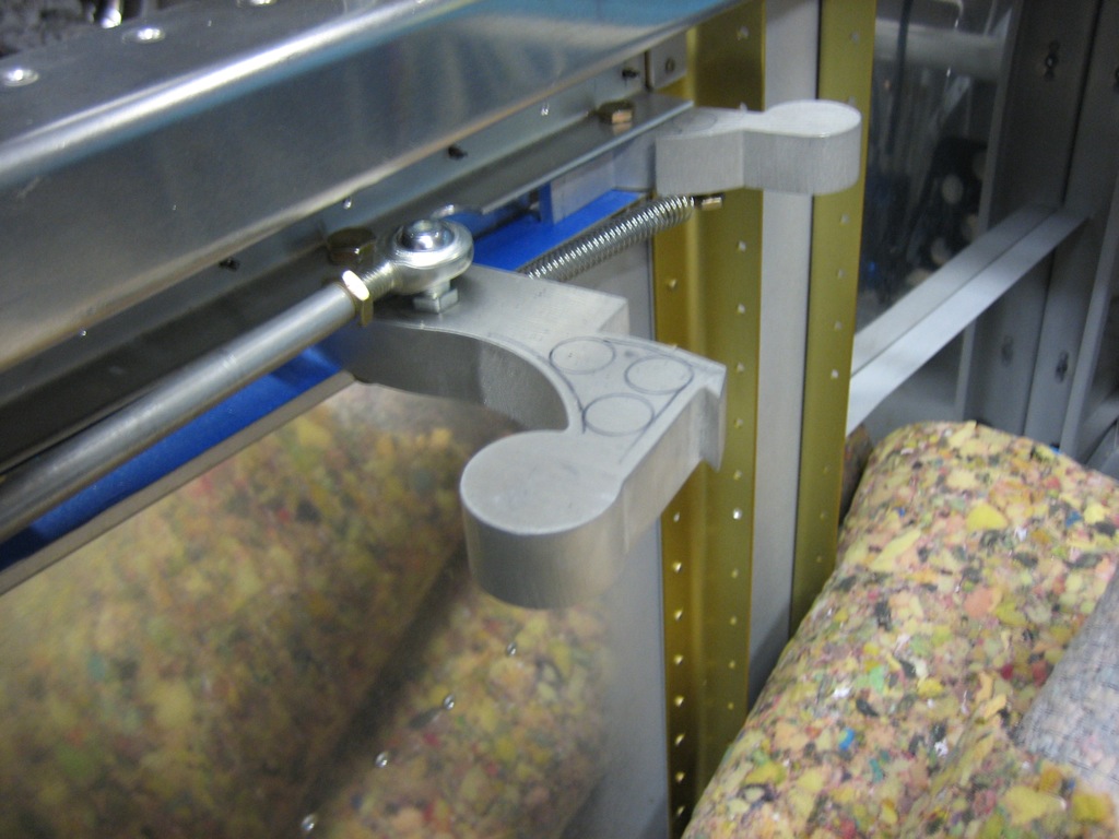
Worked on Canopy Hinge Blocks

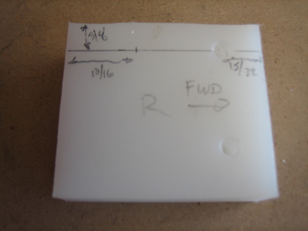
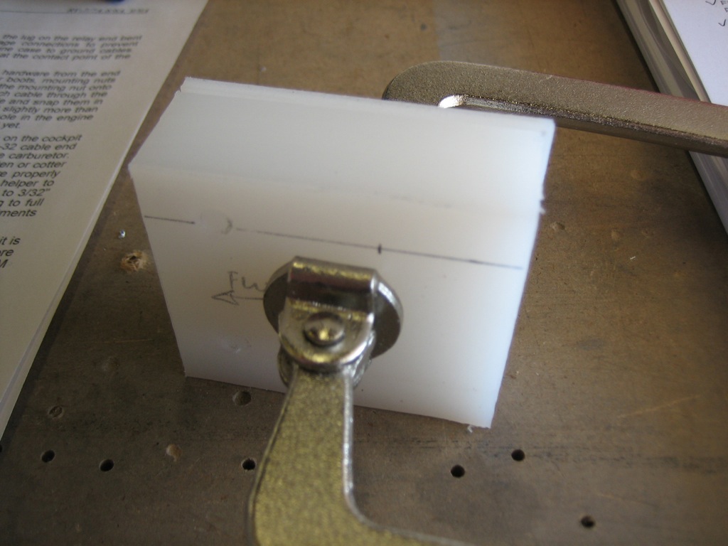
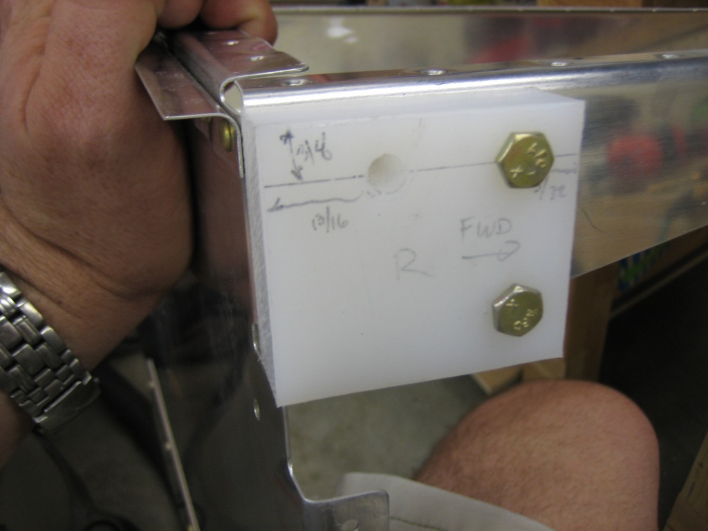
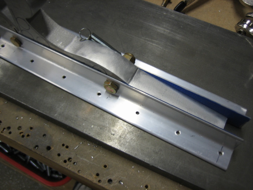
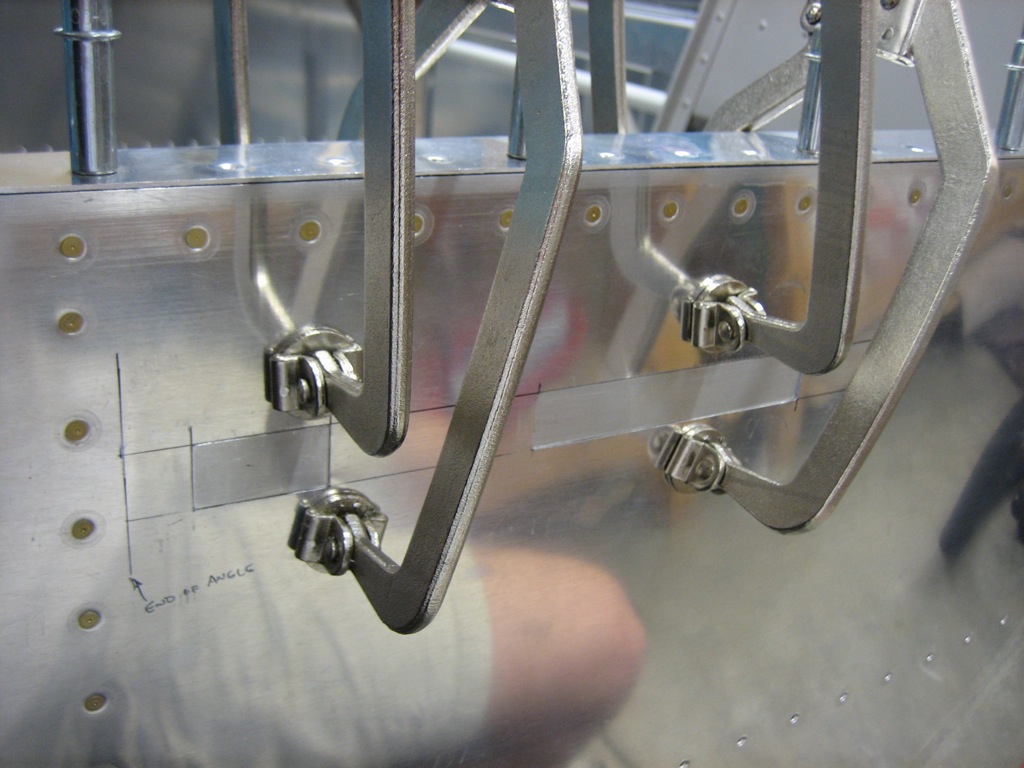
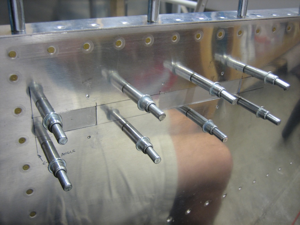
I clamped the C-617 canopy hinge blocks to the forward ribs and marked the forward holes with a #12 bit.  I then took the blocks off and drilled these to #10 on the drill press.

I then clamped the C-617 and C-618 blocks together and transferred the holes.

Worked on Canopy Hinges and Latch

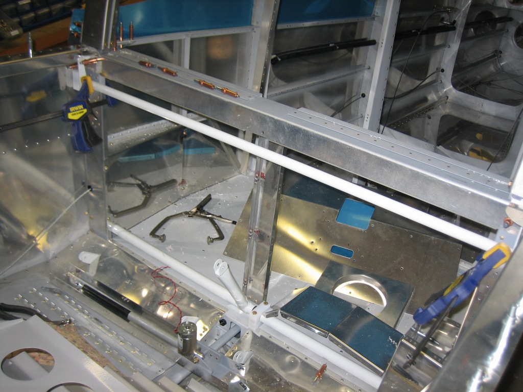
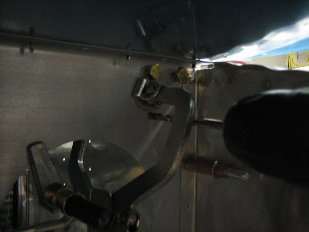
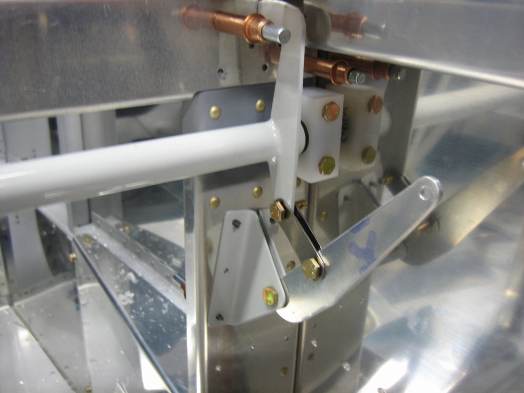
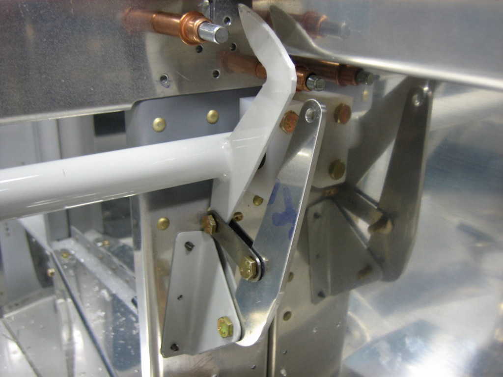
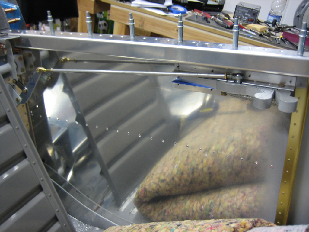
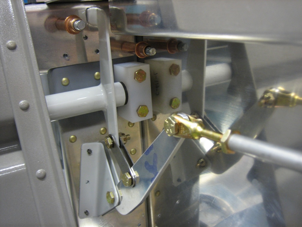
While I was working on the canopy hinge, my buddy Andre worked on the canopy latch.  The torque tube is positioned and clamped in place.

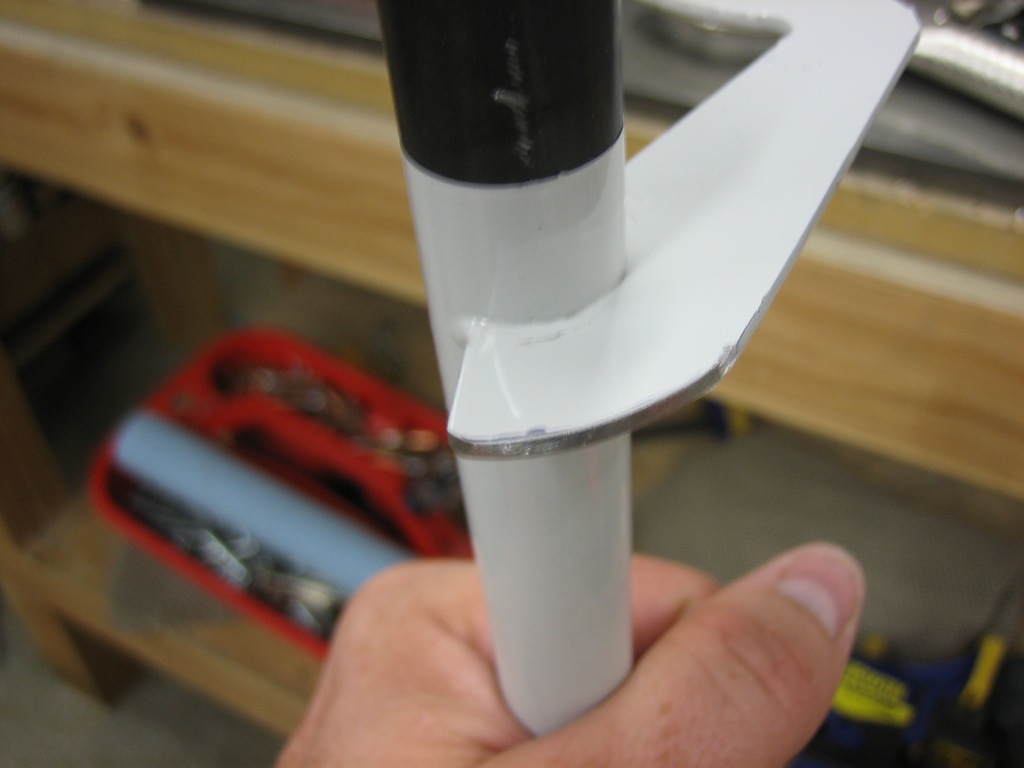
Here you can see that the finger on the end of the latch penetrates the hole in the seat back bulkhead.  After ensuring everything was positioned properly, we marked the position of the holes in the bushing blocks with a #30 bit.

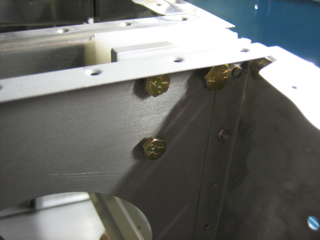
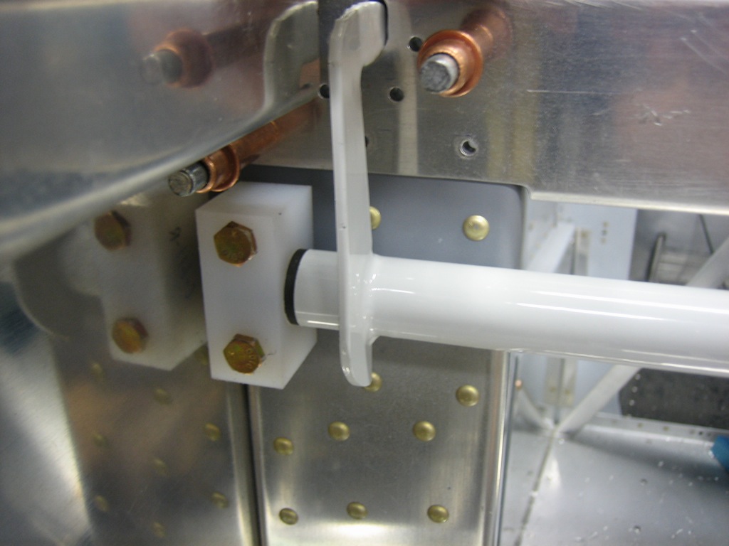
After match drilling the C-619 spacer (aluminum spacer between the plastic blocks), I reinstalled the center subpanel and used bolts placed loosely through the holes to keep everything aligned.

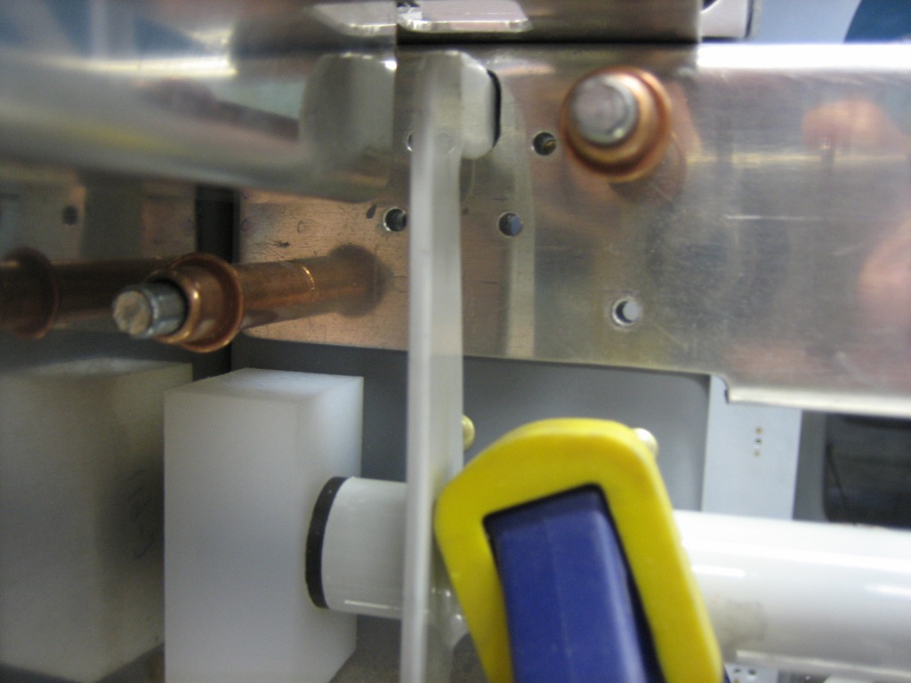
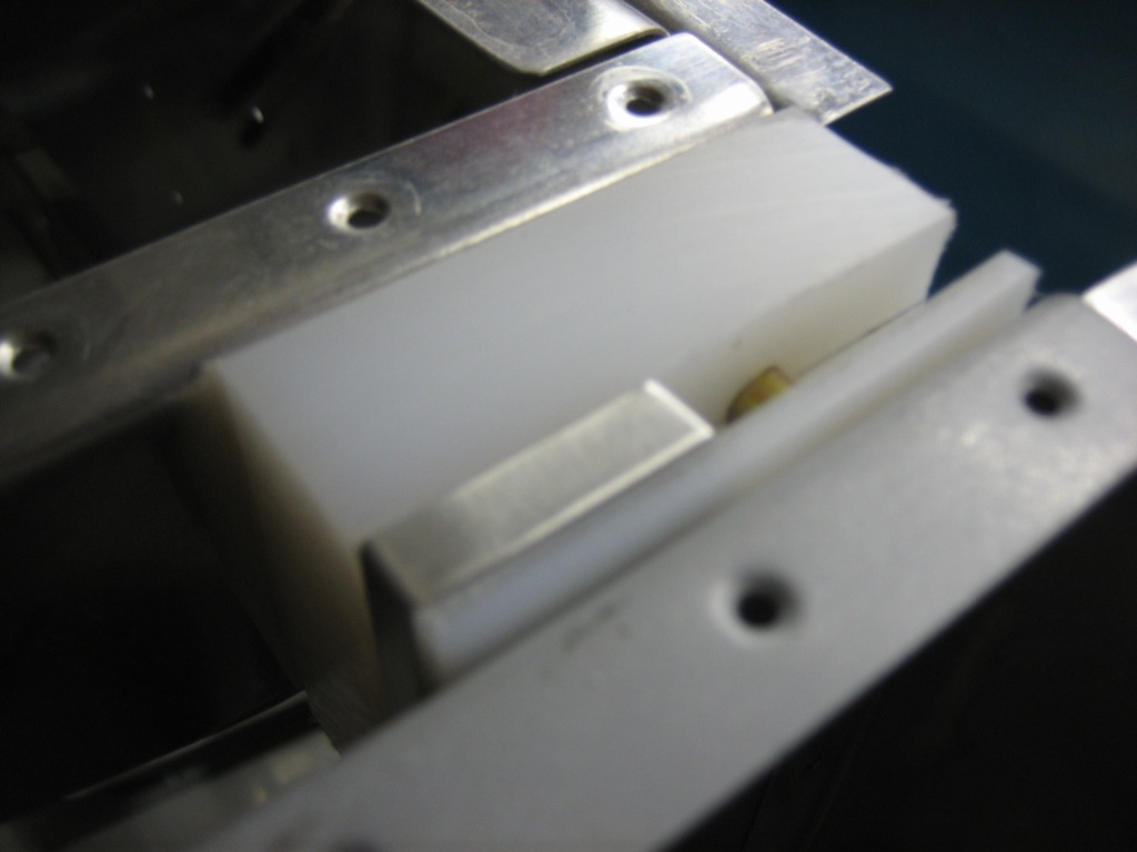
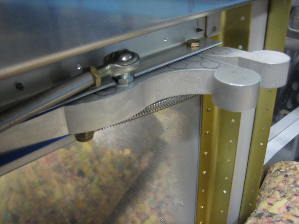
Here’s a closeup showing how the aluminum spacer is sandwiched between the two plastic blocks.  The spacer is the exact width of the hinge bracket on the canopy.

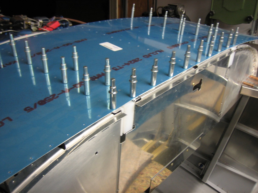
Finally, I reinstalled the top skin to pull everything into its final position.

Finished Canopy Hinge Blocks

I clamped all of the canopy hinge block components together and drilled #12 holes through the forward fuselage channels.

After these were drilled, I removed the center subpanel and installed the C-617 blocks using bolts through the newly drilled holes and then match drilled the 1/4″ hole.

I spent the rest of the evening preparing another hose order for Bonaco.  There will still be at least one more hose order after this containing the fuel lines from the servo to the spider and the oil lines from the accessory case to the oil cooler.

Back from Oshkosh

I got back from Oshkosh today.  I had a few goals for the trip:

Audio Panel: I had been trying to decide between the Garmin GMA 240 and PS Engineering PMA5000EX.  They’re both really nice units and each have their strengths and weaknesses.  The PMA5000EX unit has the IntelliVox (auto-squelch) feature while the GMA 240 has the old style manual squelch control.  However, the front panel controls on the GMA 240 are substantially more user-friendly and intuitive.  I had been leaning pretty heavily towards the PMA5000EX, but after the show I’m more split.  I still need to do some more research on this.

Canopy Attach:  I have been trying to decide between screwing the canopy to the frame and gluing it on with sikaflex.  The sikaflex solution results in no holes in the canopy which dramatically reduces the chance of cracks, but it’s still a relatively new solution, so the long-term success of this solution is not proven.  The plans specify that the canopy is held on with screws all around, but the difference in the coefficients of expansion between aluminum and plexiglass is substantial, and a rigid fastener like a screw can put highly localized pressure on the canopy.  After looking at a bunch of RVs parked in the parking area, I’ve decided that I’m going to use screws along the side skirts and around the aft edge of the rear window, but adhesive across the canopy and cabin frames.  I saw one plane done like this and the results were outstanding.

Electrical System: I’ve been planning on following the AeroElectric Connection wiring diagrams (Z-13), but recently Vertical Power announced the VP-X.  This provides a solid state electrical system that is controlled through your EFIS.  The only issue is that Dynon has not announced support for this since they’re still trying to finish the SkyView system.  I think there is a high likelihood that they will provide support for it at some point though, so the question is whether it will happen by the time I need it.  The VP-X provides some really nice features though such as start button disabling, landing/taxi light auto wig-wag, flap overspeed warning, flap positioning, flap extend disable above Vfe, auto trim speed adjustment based on airspeed, better fault detection and alerting, etc.  If Dynon supported it with the SkyView, there is no question that I would go with it.  I could gamble that it will be done by the time I need it, but then I could be grounded if it wasn’t.  I also need to do some more research on this and see if I can put the decision off as long as possible.

Started Canopy Latch

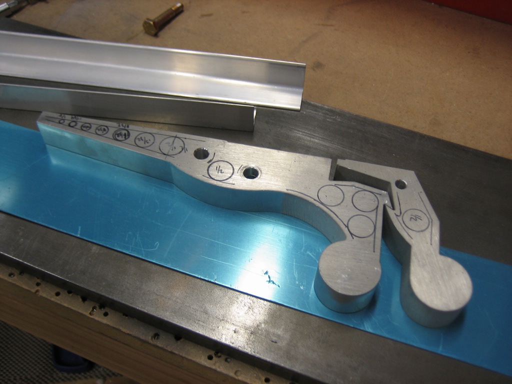
I started working on the canopy latch.  Instead of the latch included with the kit, I’m using the canopy latch from fairings-etc.com.  This will be perfectly flush on the outside of the plane instead of the protruding fingers of the stock latch.  The only disadvantage is the weight.  These are cut from 5/8″ thick aluminum stock instead of the 1/8″ thick stock used in the kit latch, so they’re quite a bit heavier.  I laid out a few lightening holes, but I may just drill holes part way through from the bottom side to remove weight without changing the appearance.

The quality of these as received is pretty marginal.  The cut edges are all very rough and will require quite a bit of hand work to smooth out.  Also, the predrilled holes are too large which makes for a sloppy fit around the pivot bolts.  I’m going to have to ream these holes out larger and fabricate some bushings to eliminate the slop.

The other problem with these latches is that the outer skin of the aircraft is used as the spring to keep the aft piece (on the left in the picture) engaged with the forward piece.  This seems like a pretty poor design as it will repeatedly flex the outer skin and could fatigue it over time. Fortunately, I knew this prior to purchasing the latch and ran across a good way to solve the problem on Roee Kalinsky’s site.

Worked on Canopy Latch and Engine Start Button

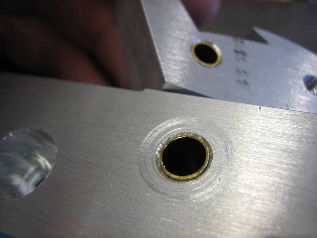
I stopped by the hardware store this morning and picked up some 7/32″ and 9/32″ brass tubing.  I then drill out the latch pieces so that these are a press fit into the holes.  This will allow the brass tubing to rotate around the bolt.  This totally fixed the sloppy fit and the bolts are a slip fit through the holes now.  I’m not going to install these permanently in the holes yet since I’m planning on having the latch components hard anodized.
I also drilled the latch attach angles to the latch components.  Here is the latch temporarily assembled so that I can check the clearances and movement.
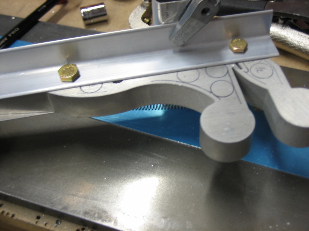
On the other side, you can see how the latch sits proud of the attach angles.  This is because the attach angles will sit flush with the inside of the skin, but the latch components should be flush with the outside of the skin.  The skin is 0.032″, but I positioned these currently 0.036″ proud of the angles.  After I get them back from the anodizers, I’ll file the outside faces flush with the side of the plane since they’ll be painted the same color as the exterior.
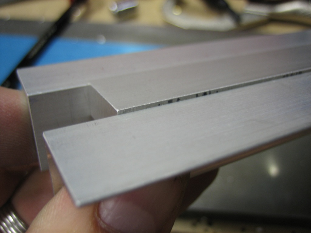
I’ve temporarily clamped a piece of scrap material across the outside face to simulate the skin since the skin acts as a stop for the forward catch.
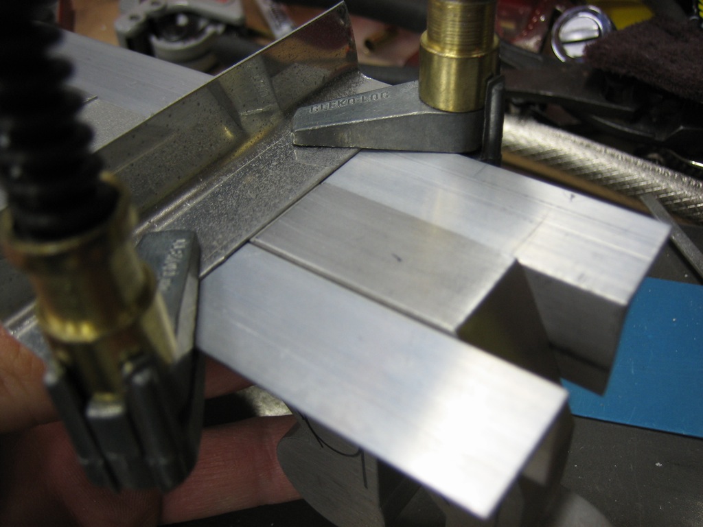
To open the latch, you push forward on the forward knob until the aft part is released.
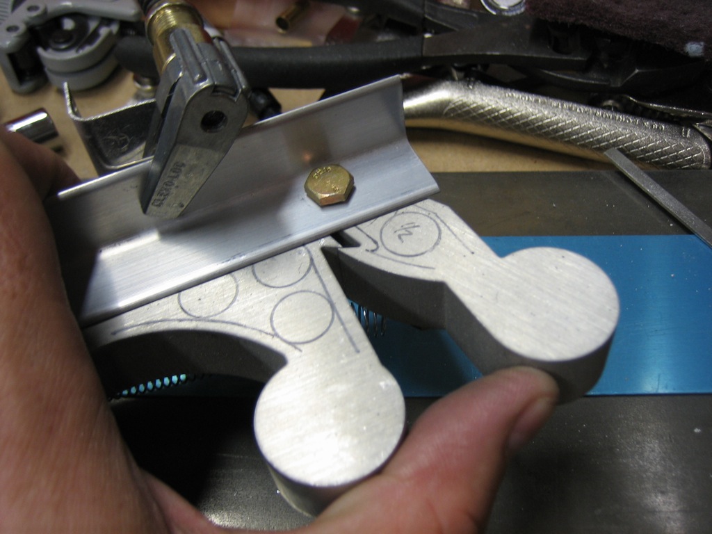
Once the latch is released, the aft part pops back.
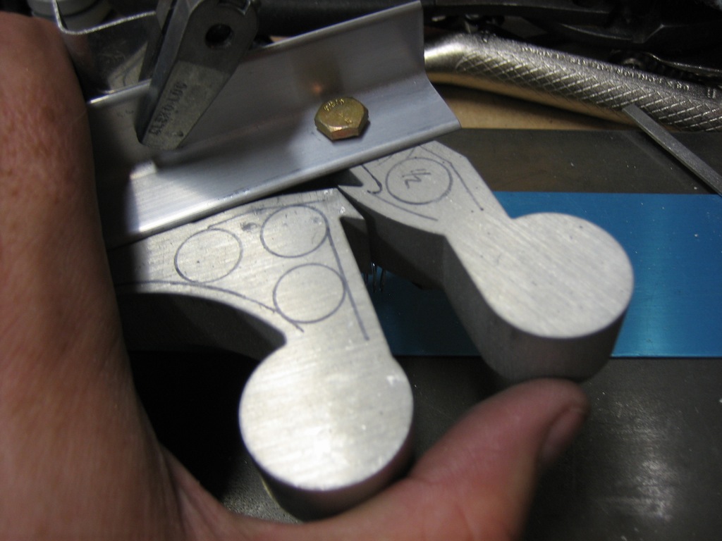
It can then be pulled aft to release the canopy.
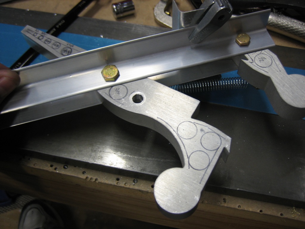
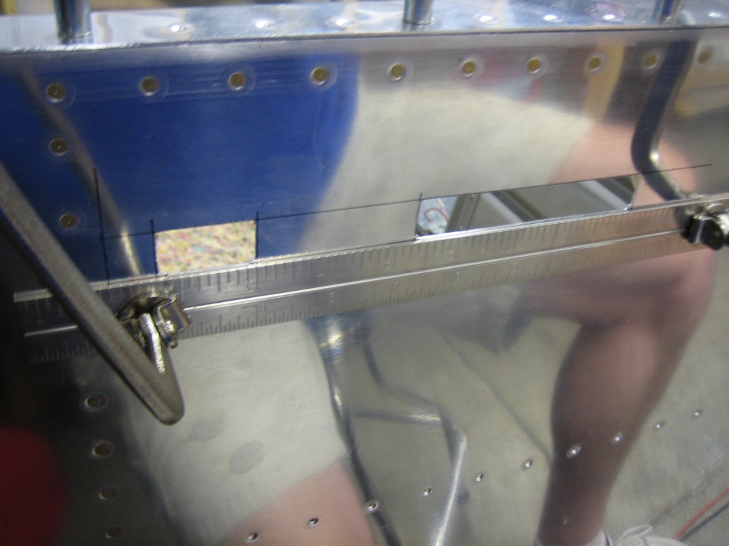
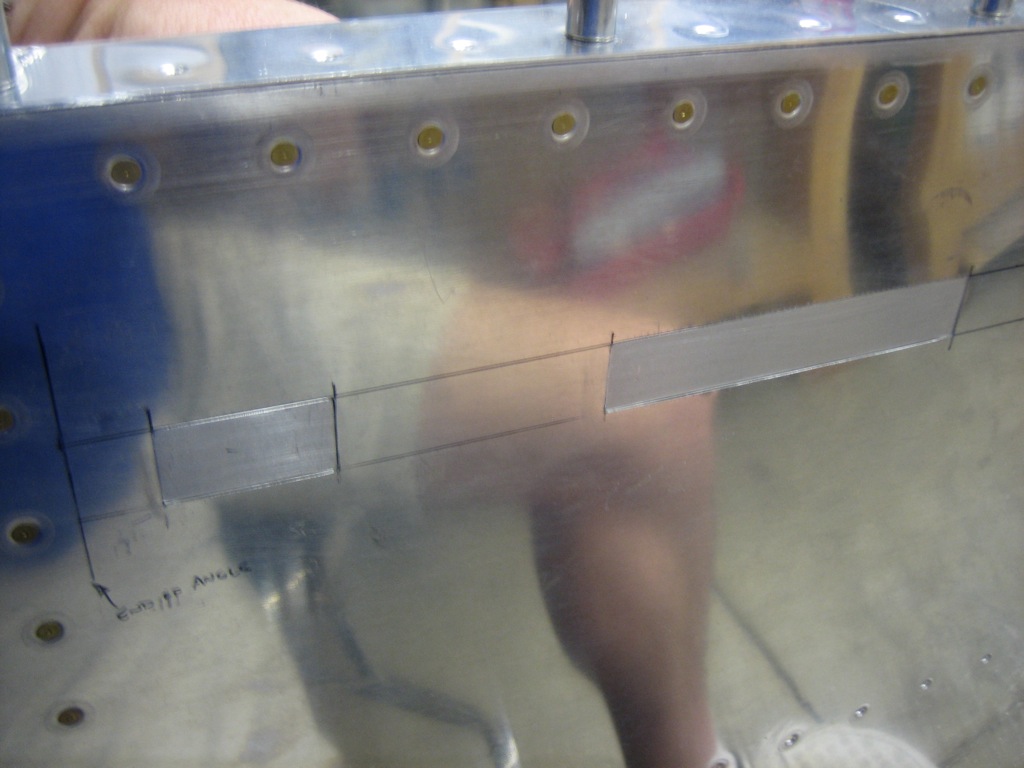
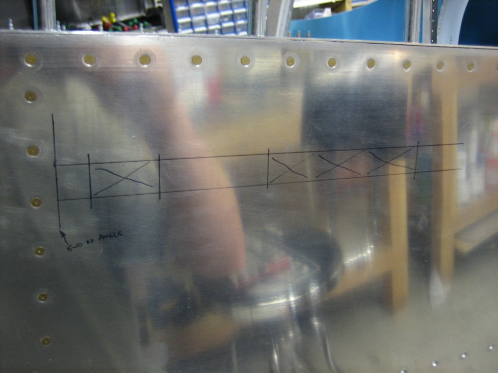
Finally, I laid out the cutout for the side skin.  It’s late, and I want to do this when I’m fresh, so I’ll start this tomorrow.
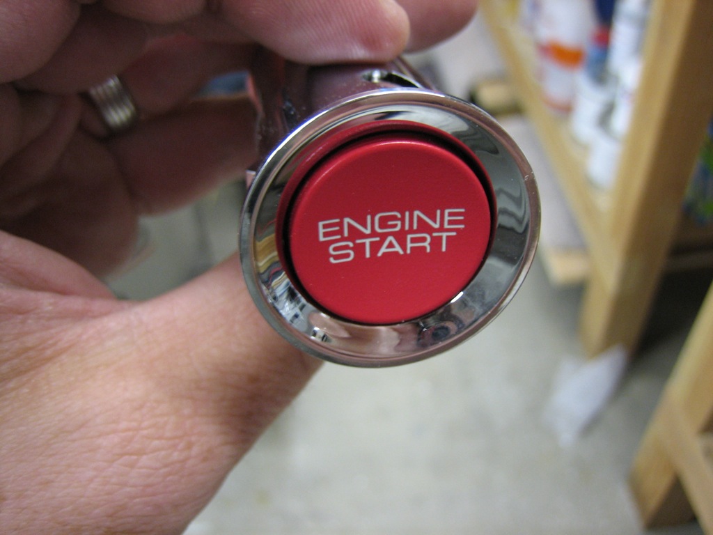
I wasn’t completely tired, so I wanted to figure out how the engine start switch will be wired.  I don’t think I’ve mentioned it before, but I’m using the engine start switch from a Honda S2000.  It has an integral light, but it’s really dim and can’t be controlled separately from power to the switch.
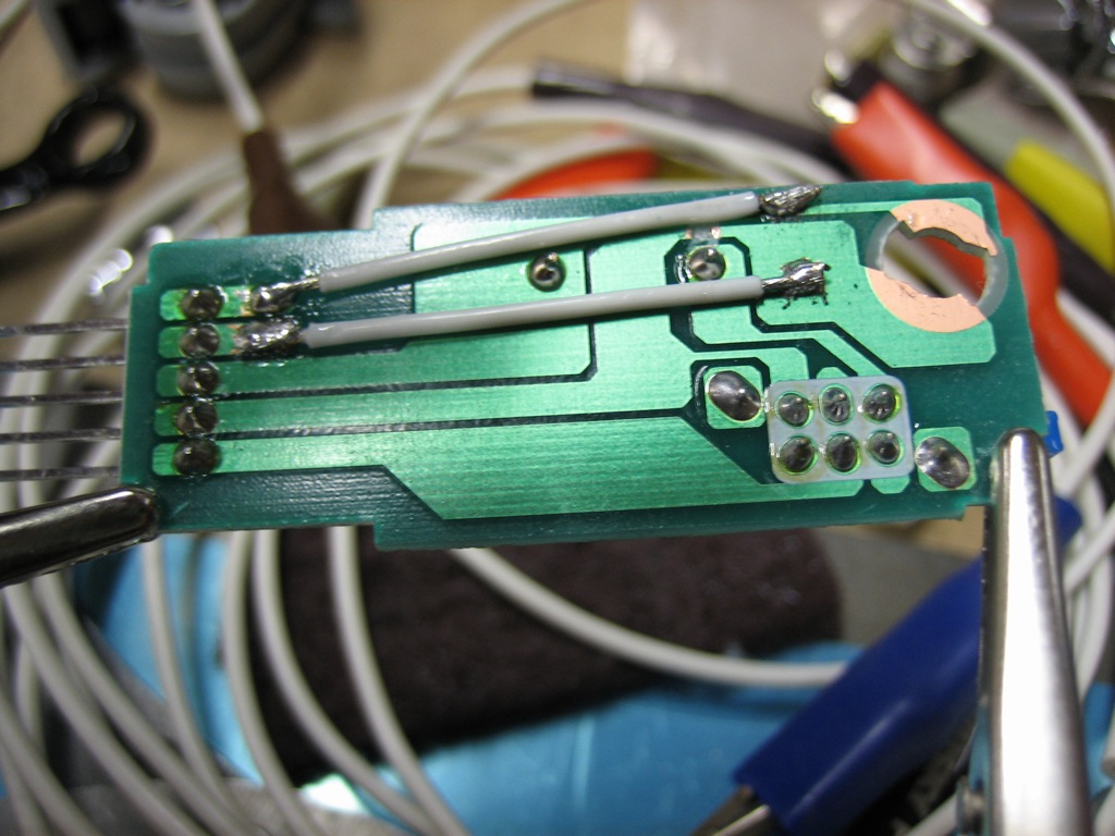
To solve this, I disassembled the switch, cut the traces to the light and wired them to the two unused pins on the connector.  If I end up using the Vertical Power VP-X, it can turn on the light when the start button is enabled.  I think I’m going to have to use a relay between this switch and the starter relay since I’ve heard the starter relay pulls about 4 amps and I don’t think this switch can handle that kind of current.  I need to confirm this though.
Cut Canopy Latch Slot

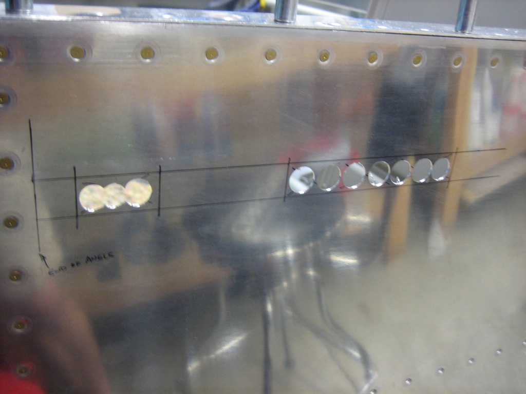
I double checked the measurements I made last night and found them spot on, so I got started cutting out the slots.  I used a unibit to remove most of the material.

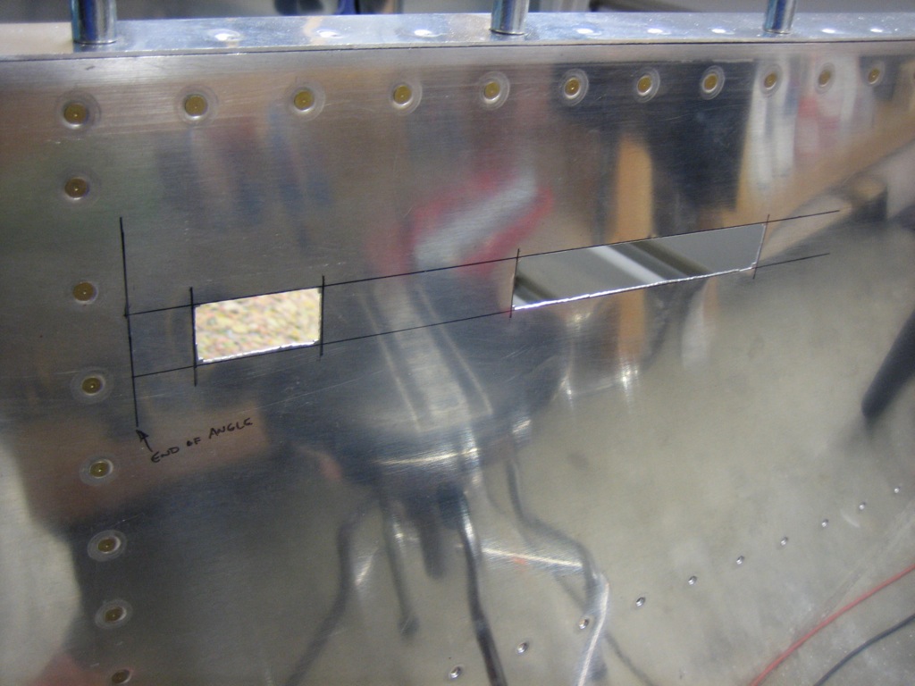
I then spent a few minutes with the hand nibbler removing most of the rest of the material to just inside the lines I’d marked.

I then clamped a steel straight edge along the line I drew and filed down to the line.  The steel straight edge serves two purposes, it helps ensure that the filed edge is perfectly straight and it prevents filing past the line since the file basically stops cutting when it hits the straight edge.

After about 30 minutes of filing, the latch fits pretty well in the slots.  I had to round the corners of the latch pieces slightly since I didn’t want a sharp inside corner on the skins because that could lead to cracking.  At this point, the latch operates pretty well; good enough that I can go ahead and drill the attach angles to the skin.  Once the final position of the latch is defined, I’ll finish filing the edges to provide even clearance all around the latch.
More Work on Canopy Latch

I took a break from the canopy latch handle and went back to the latch itself.  I trimmed the lower ear as specified in the plans for weight savings.  After taking this picture, I used the touch-up paint that matches the powder coat to cover the bare metal.

Next, I drilled the bushing blocks out to full size and temporarily bolted the latch into place.

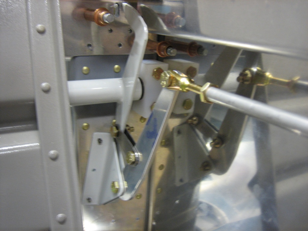
Finally for this evening, I fabricated the idler and linkage.  The upper hole in the idler will connect to a pushrod whose other end is attached to the canopy latch handle.  Here’s the mechanism in the latched position.

And here’s the mechanism in the unlatched position.

Finished Fabricating Canopy Latch

I laid out and drilled the holes on the attach angles.  I also put four layers of blue painters tape between the angles and the latch pieces.  These add about 0.018″ of clearance between the pieces to make room for the 0.016″ thick UHMW tape that will be installed in the completed assembly.

I then clamped the latch in place.

And backdrilled through the skins.  This is the opposite of the way the Van’s plans specify, but it ensures that the latch is perfectly centered in the slots and the holes are centered in the attach angles.

Finally, I fabricated the connecting rod that ties the latch handle to the idler.  I ended up needing to make mine about 1/8″ longer than the plans specify.  The tube has to be cut to length and then the ends tapped out to 1/4-28 for the rod-end hardware.

Here’s a closeup of the handle end.  You can see how I had to notch the upper attach angle for the rod-end.

With the handle in the closed position, you can see how the idler is pulled forward which pushes the latch finger into the slot on the bulkhead.

Here is the latch handle pulled back all the way.

With the latch handle pulled back, you can see how the idler is pushed back which pulls the latch finger forward.