Parts Orders

I didn’t get any work done on the plane today, but I spent several hours putting together orders from Aircraft Spruce, Avery Tools, and Van’s for various bits of hardware, fluid fittings, firewall pass-throughs, pressure manifold, prop governor bracket and other miscellaneous parts.

I also got a Dymo Rhino Pro 3000 label maker today and ordered some heat shrink tubing cartridges for it.  I’m going to use these to label all of the wiring in the plane.

Worked on Seat Backs

I’ve heard that most if not all builders have a problem with the seat backs interfering with the roll bar.  I took a measurement off the plans, and the rollbar is 3.5″ from the outer skin to the horizontal bolt on the inboard edge.

I measured 3.5″ in from the skin along the front edge of the seat back support and made a mark.

With the outboard edges of the seat backs positioned flush with the end of the seat pan hinges…

…the top of the seat back extends past the mark by just over 1/4″

If I move the seats over by one eyelet…

…then the top of the seat backs are inside the roll bar by a little less than 1/4″.  Building the seat backs according to plans, but swapping the left and right seats will result in this inset.

I cut the lower hinge for the left seat and match drilled it and the lower angle to the seat back.

Here’s a closeup of the lower end of the angle showing the notch that is cut to make room for the hinge.

With the left seat back installed on the right side of the plane, I was surprised to see that the seat back was perfectly in line with the cutout for the controls.  If the seats were installed according to plans, not only would they interfere with the roll bar, the stick would not be centered between your legs.

Work on Seats, Engine Accessories

I drilled the upper seat back adjustment to the right seat back.

Here is the seat installed temporarily.  I still need to drill out everything to #30, but all of the fabrication is done.

Here is the upper seat back adjustment showing how the flange fits into the notches on the cross member.  Afterward, I knocked out all of the left seat except for the upper adjustment mechanism.

I found out that the new prop governor cable mounting bracket doesn’t attach to these mounting bolts, so I torqued these down and lacquer sealed them.

I also swapped the oil pressure fitting and the plug so that I have more clearance from the engine mount.  This required removing the upper hold down clip from the right mag cover plate so that I could get a wrench on this fitting.

I also installed the fuel overflow fitting.  A rubber tube will be installed here to route any fuel overflow away from the hot exhaust.

Update: This is the sniffle valve and shouldn’t be installed here.  I searched all over the engine and couldn’t find any other fittings that this could screw in to, but the engine was mounted on the palette at the time and I couldn’t see where this should actually mount.  See this entry for where this should actually be mounted.

Engine Fittings, Firewall Pass-Throughs

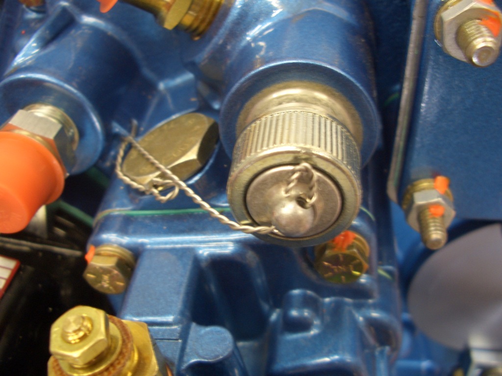
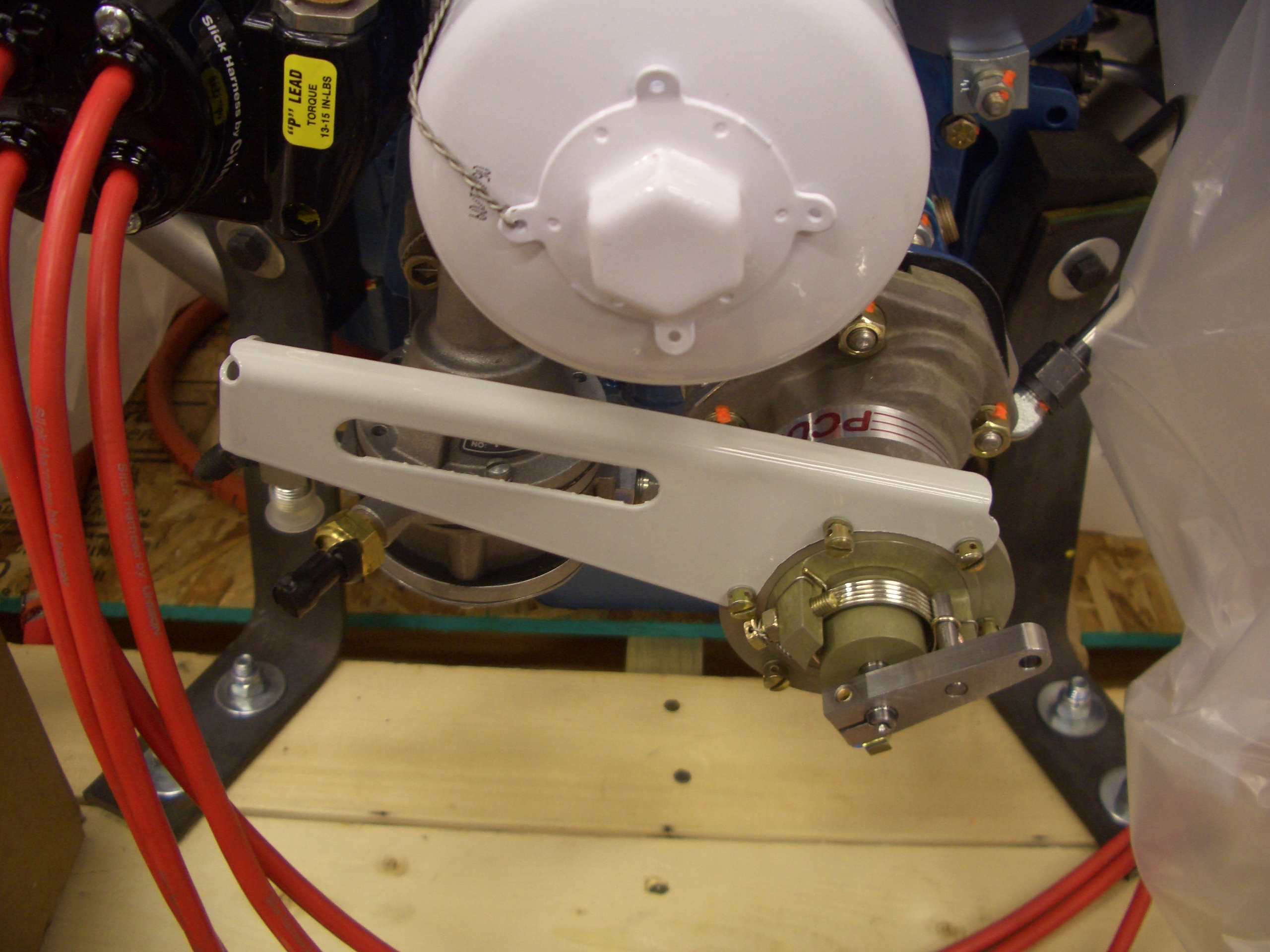
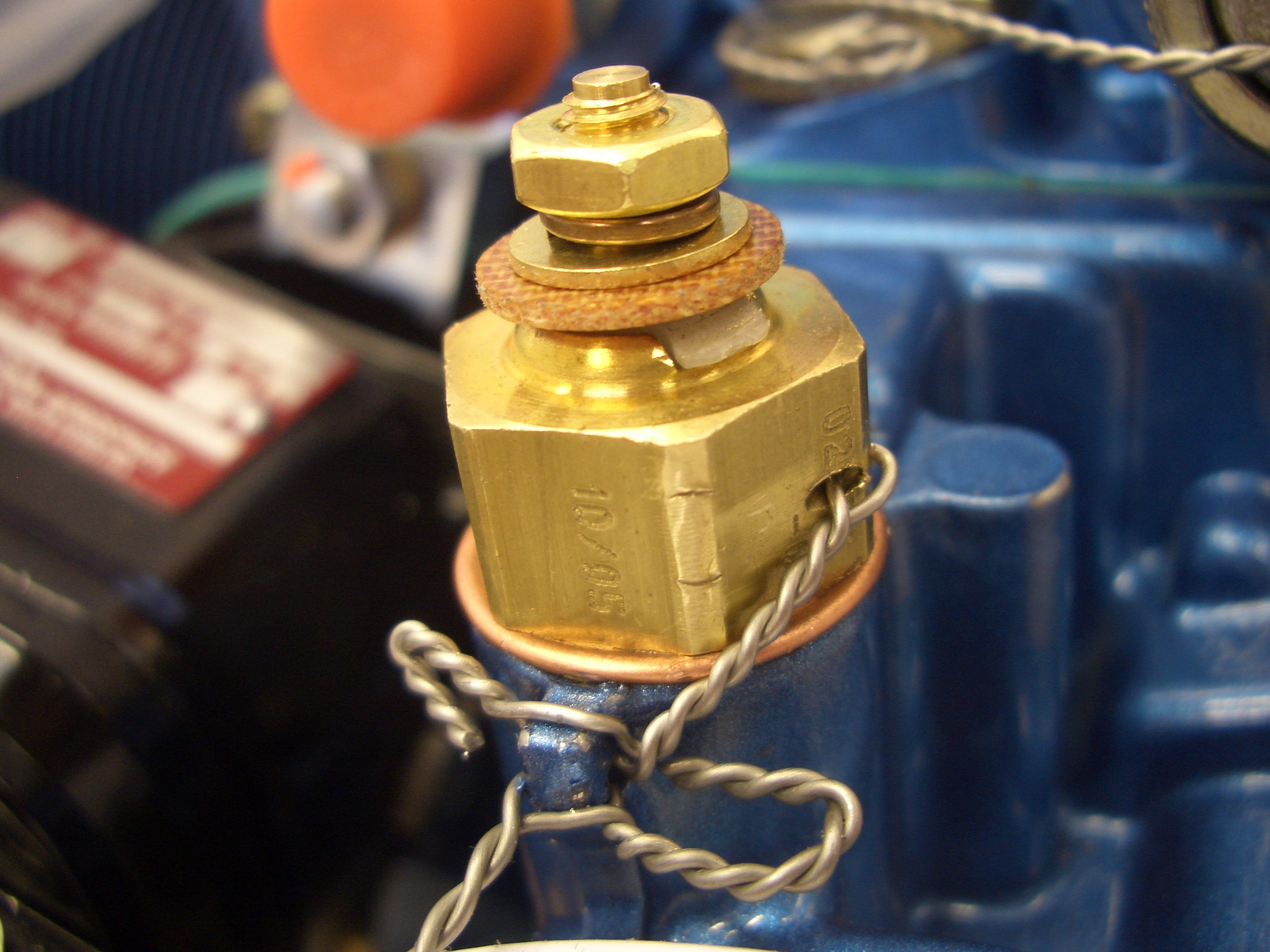
My order from Avery Tools showed up today. One of the items was a cover for the tach port. This is used for a tach cable if you have a mechanical tachometer. The Dynon will get its RPM information from the Light Speed Engineering electronic ignition box. I safety wired this, but it really can’t prevent this from unscrewing since the center part of the cap is separate from the outer part. At least it would prevent it from falling off though.

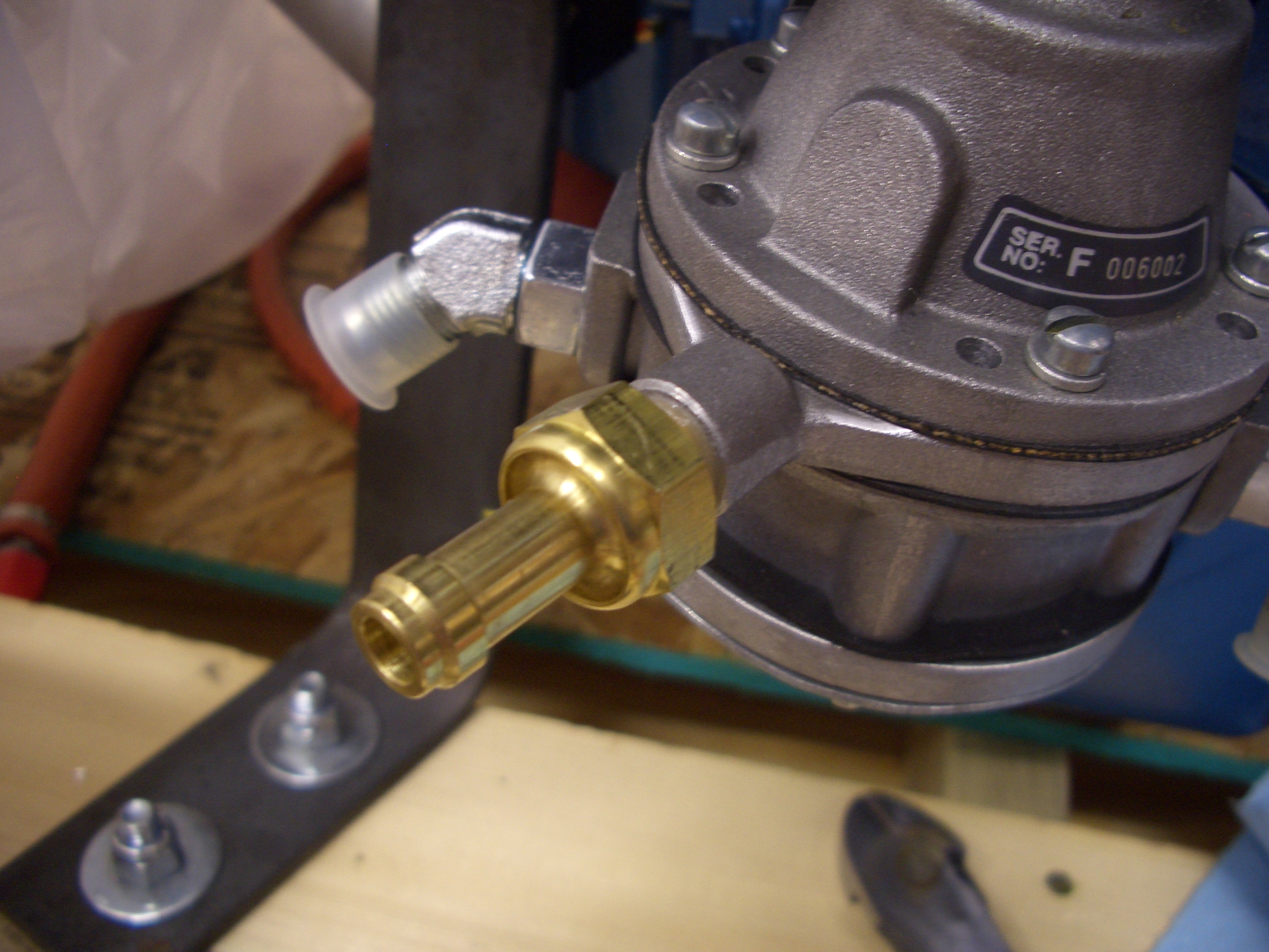
I don’t know if the high pressure fuel screen will need to be cleaned frequently or not. If so, I might want to find another place to safety wire this to so that it doesn’t run across the fitting.

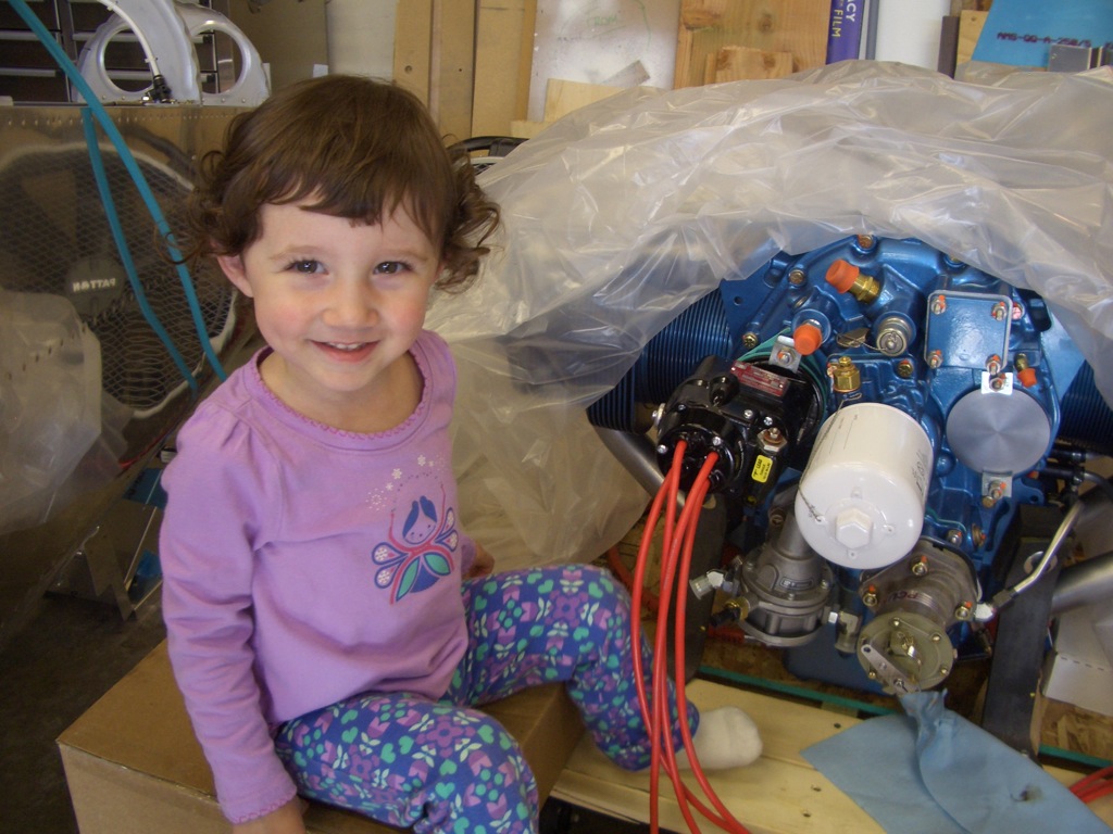
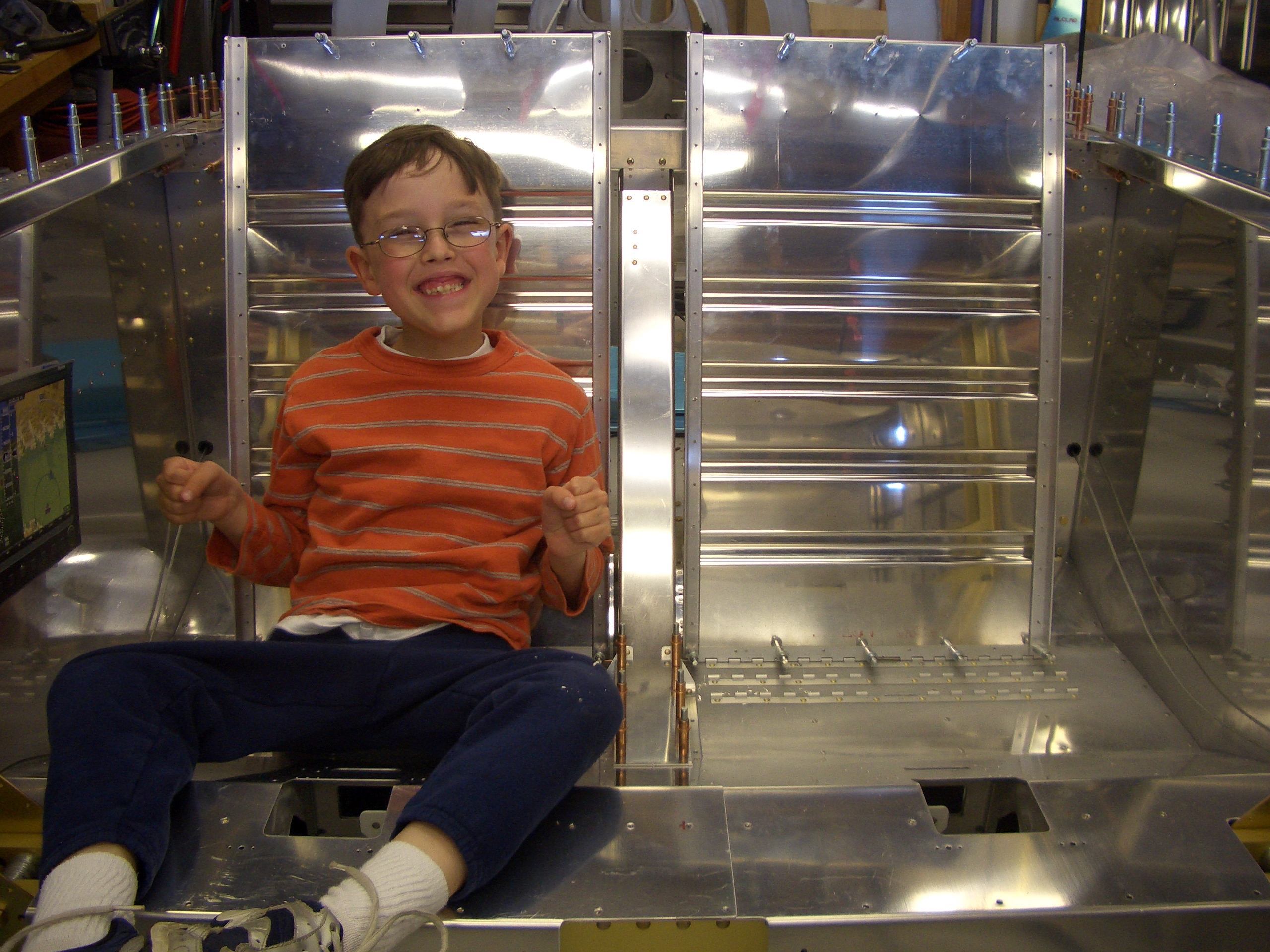
My daughter was a big help with this. She kept pointing to parts on the engine and asking “what’s that?”

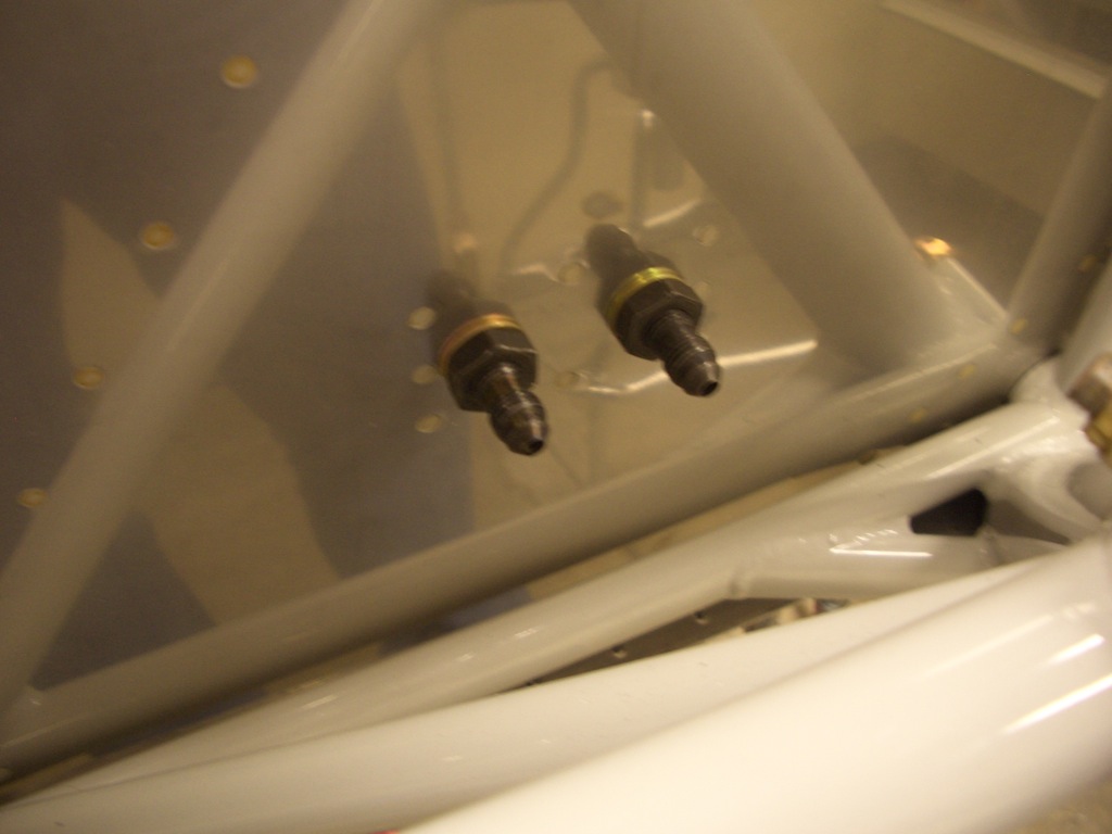
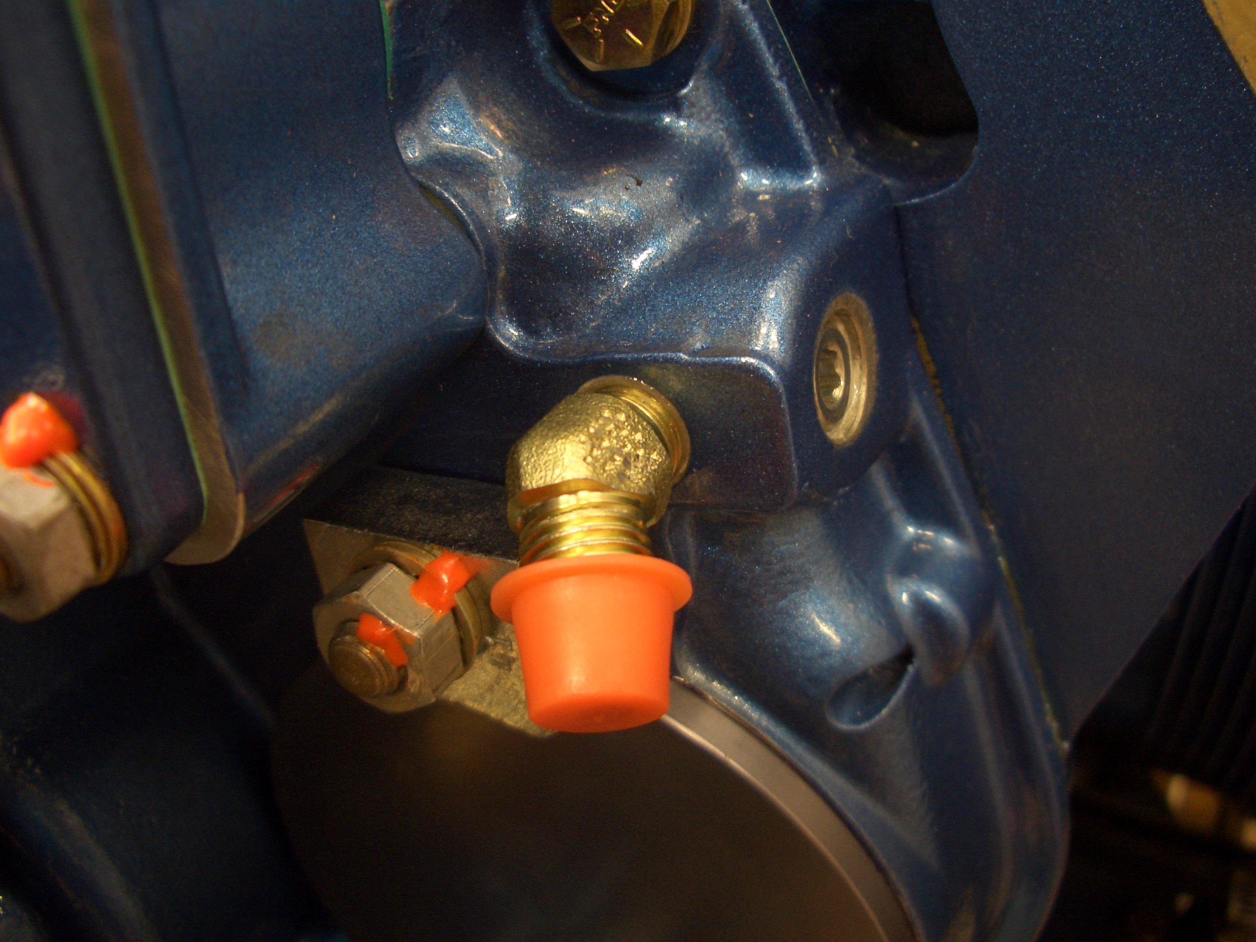
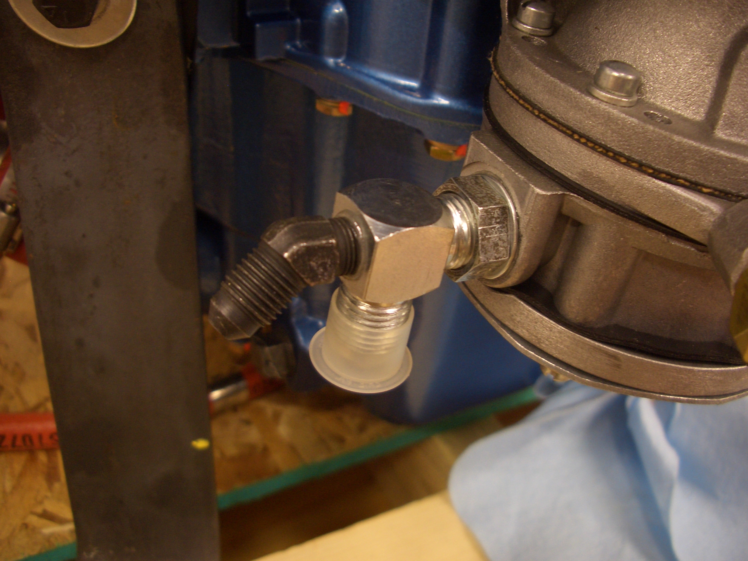
I also removed the regular 45º fuel outlet fitting and installed a 90º tee fitting. The bottom silver part of the fitting will connect to the fuel injection system. The black fitting has a restrictor inside and will tie into the fuel pressure transducer.

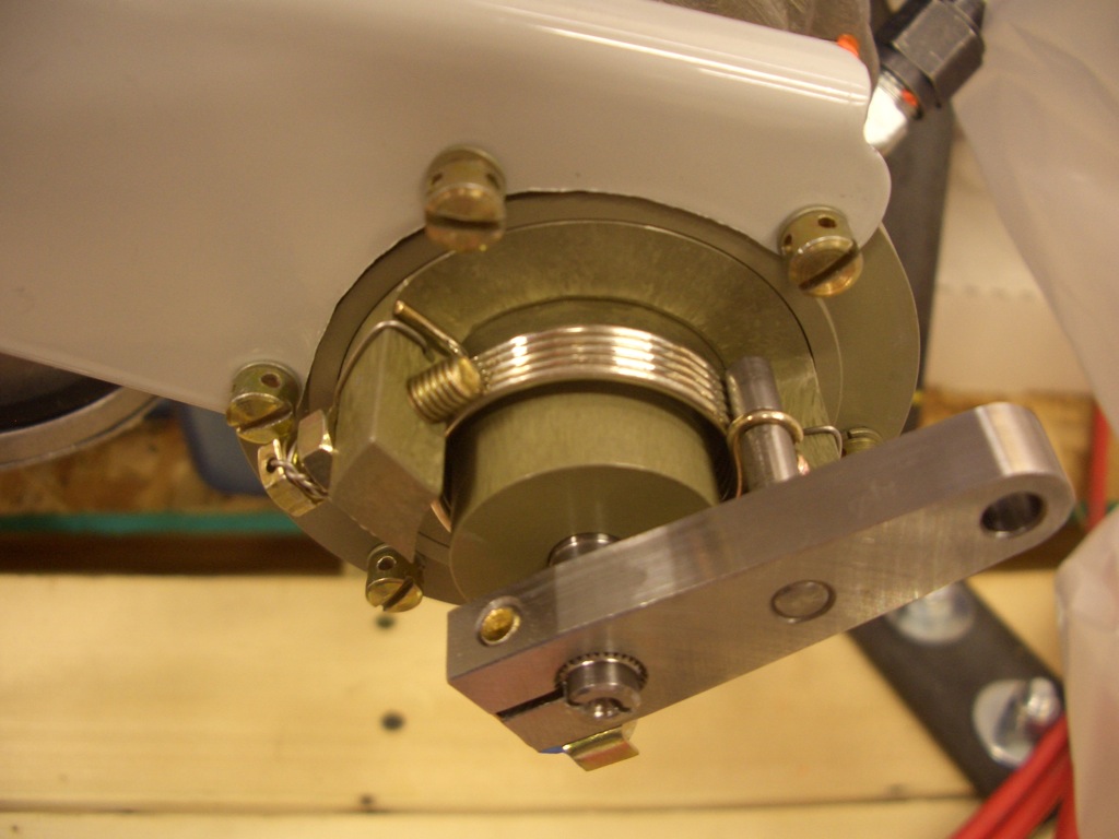
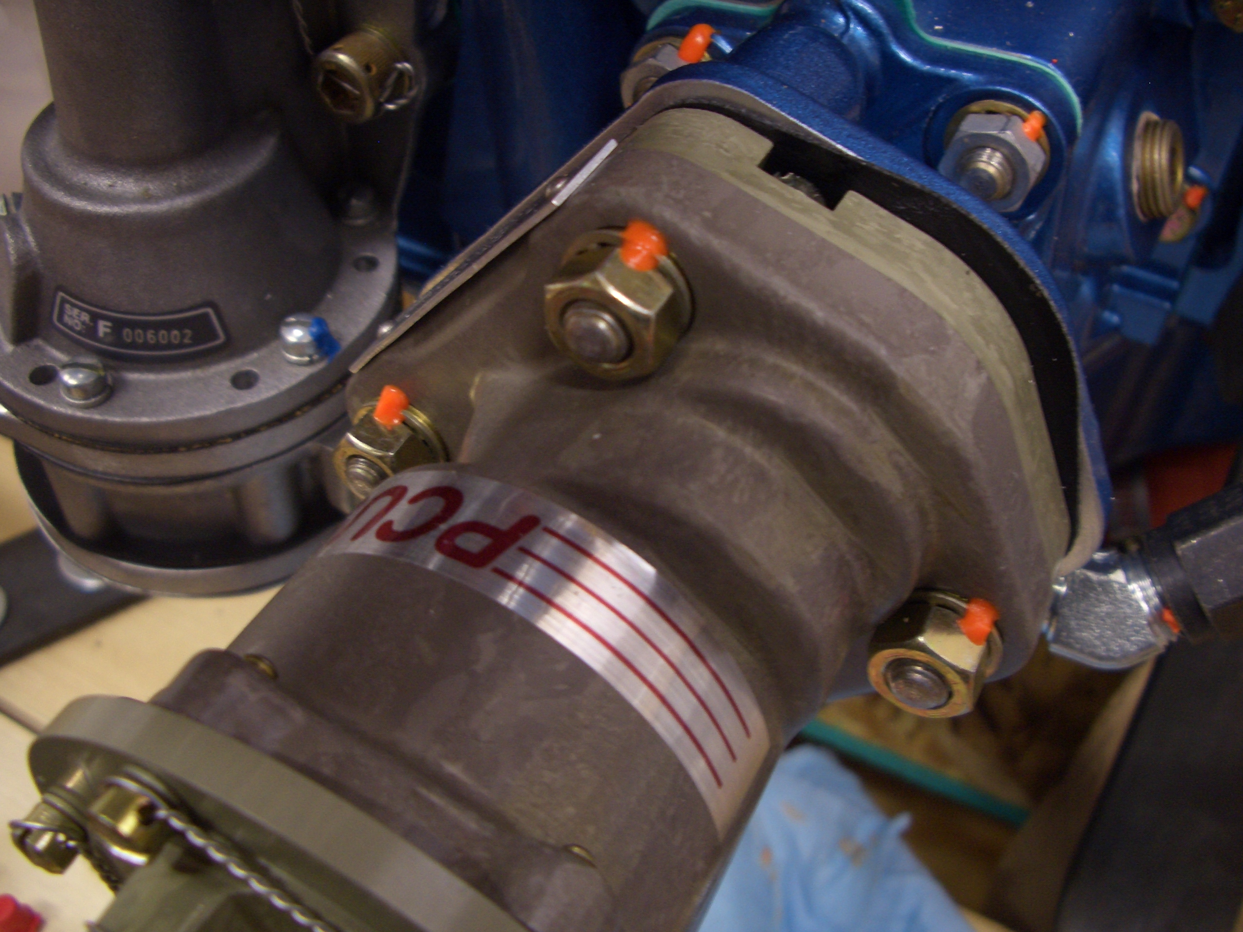
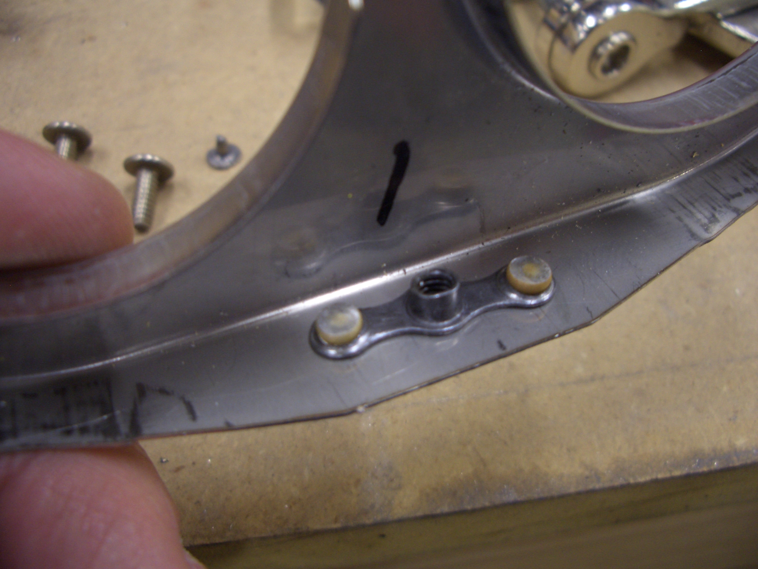
I also got an order from Van’s that included the prop governor cable bracket. After some grinding of the inner radius and elongating a couple of the holes slightly, it fits quite well. I had to cut off the safety wire for all six screw holding this ring on so that I could rotate the head and control arm. I can’t determine the final position of the control head until my prop cable shows up next week.

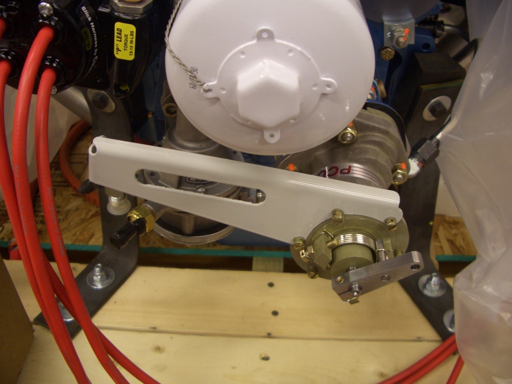
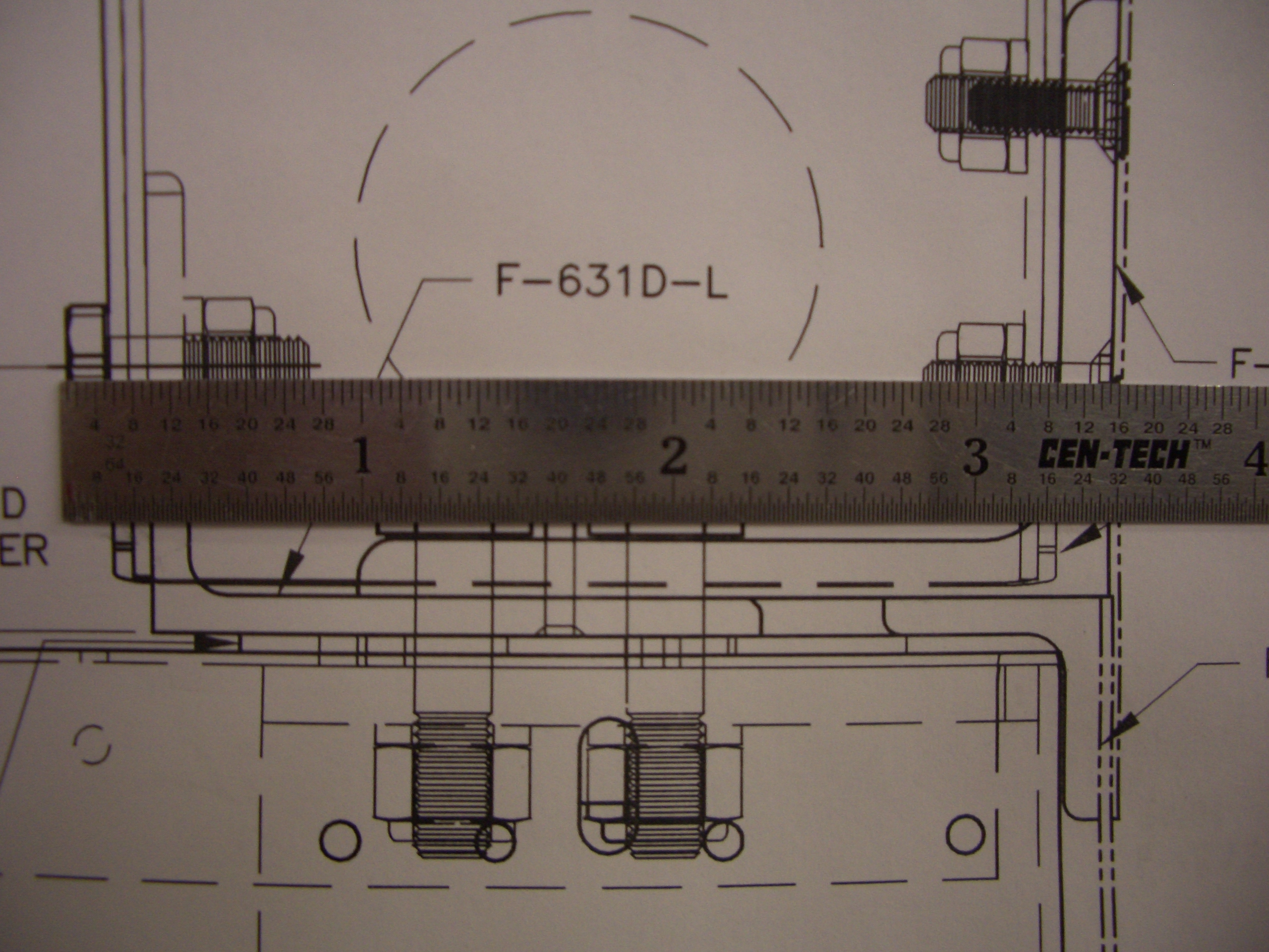
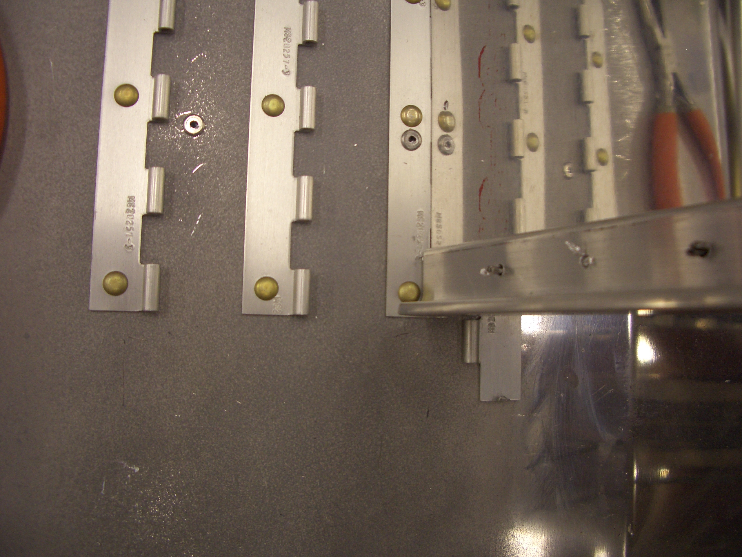
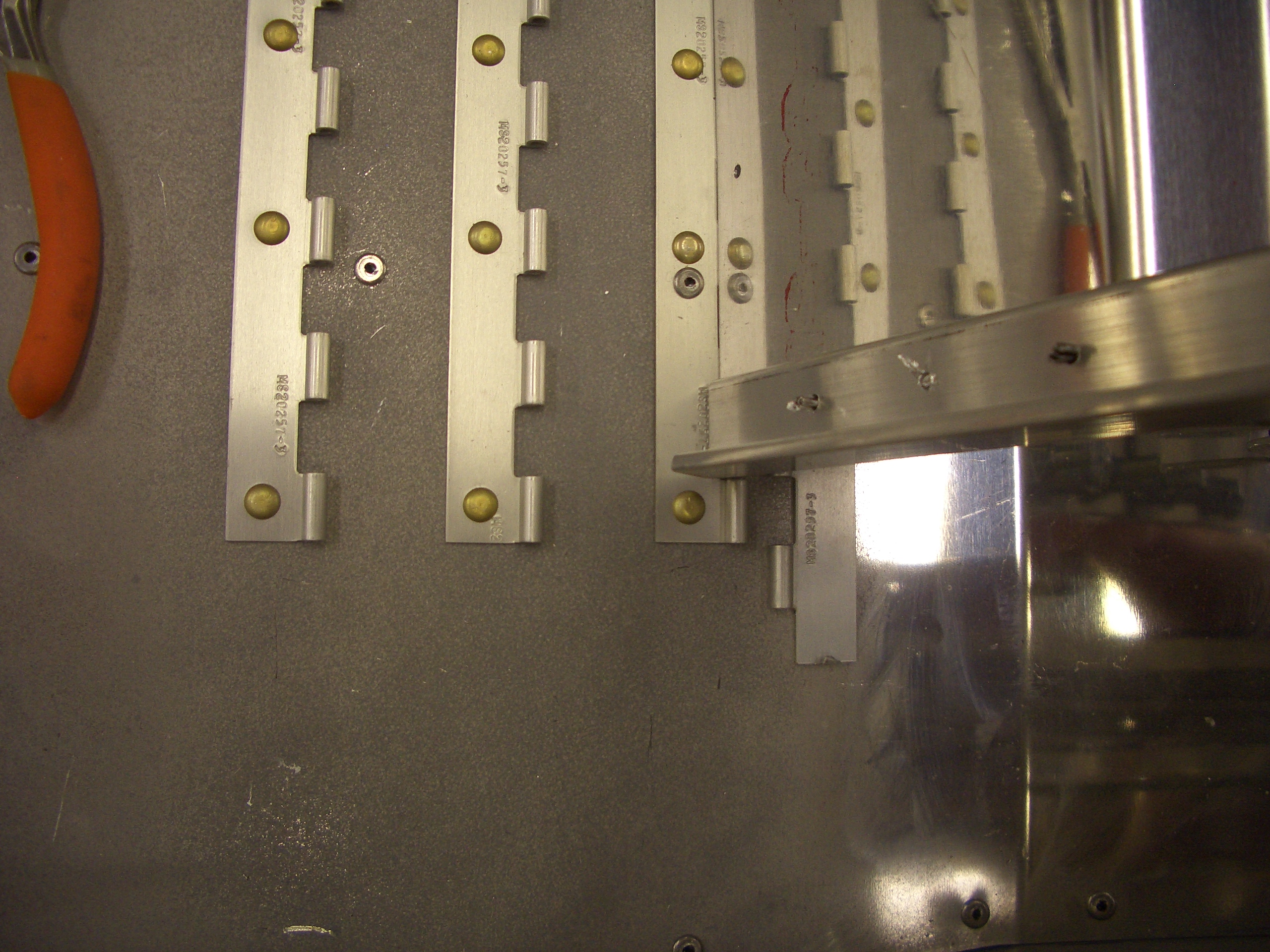
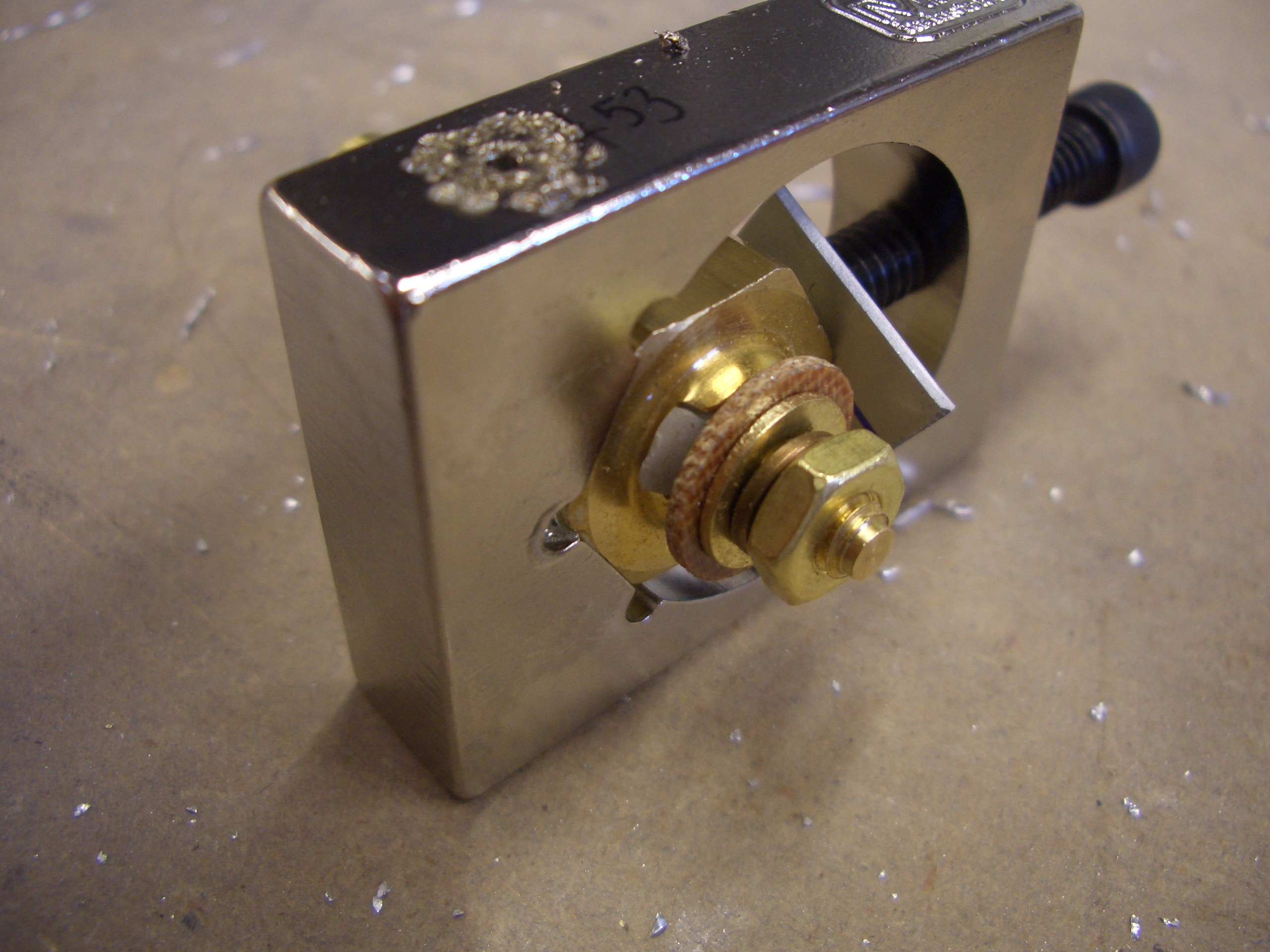
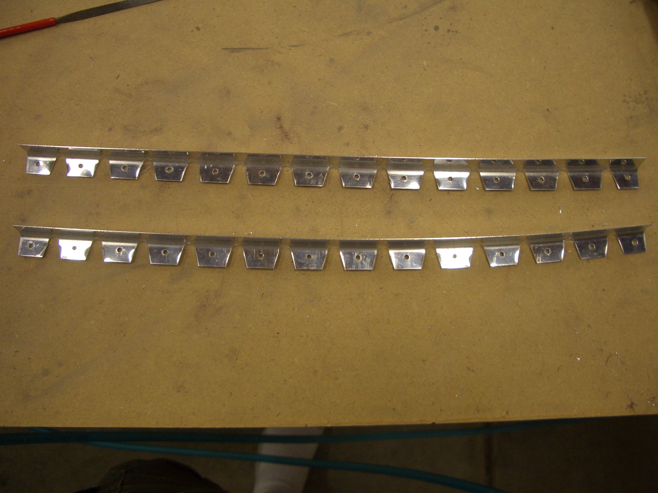
Here’s the entire bracket. The cable housing attaches to a hole on the left side and the cable passes through the slot in the bracket.

I also got an order from Aircraft Spruce that included some steel fittings to replace the aluminum ones I had installed for the brake lines. I’m trying to use steel fittings for all firewall penetrations if possible.

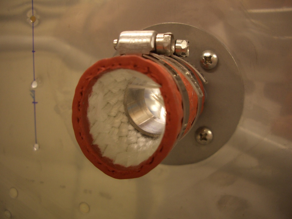
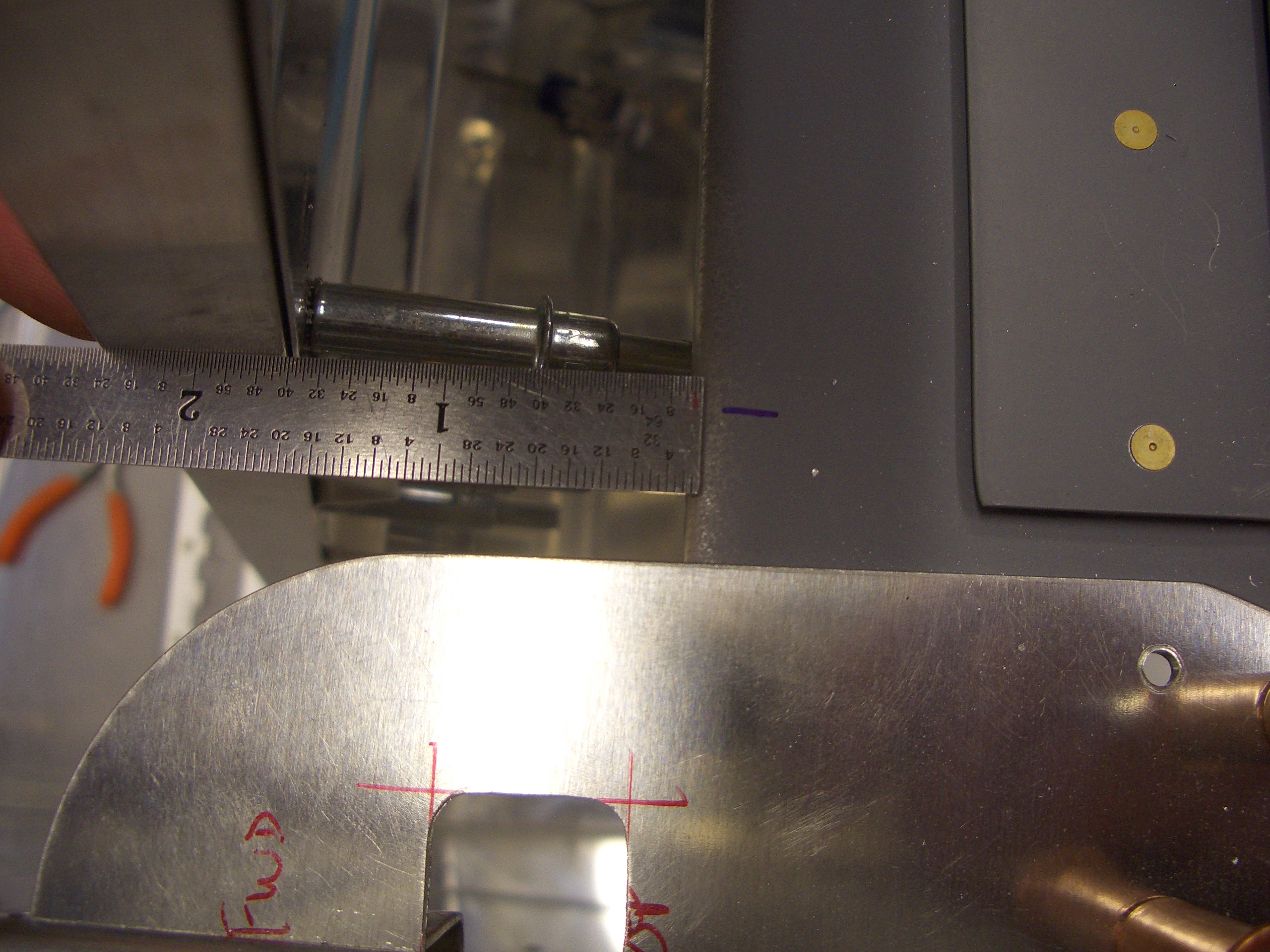
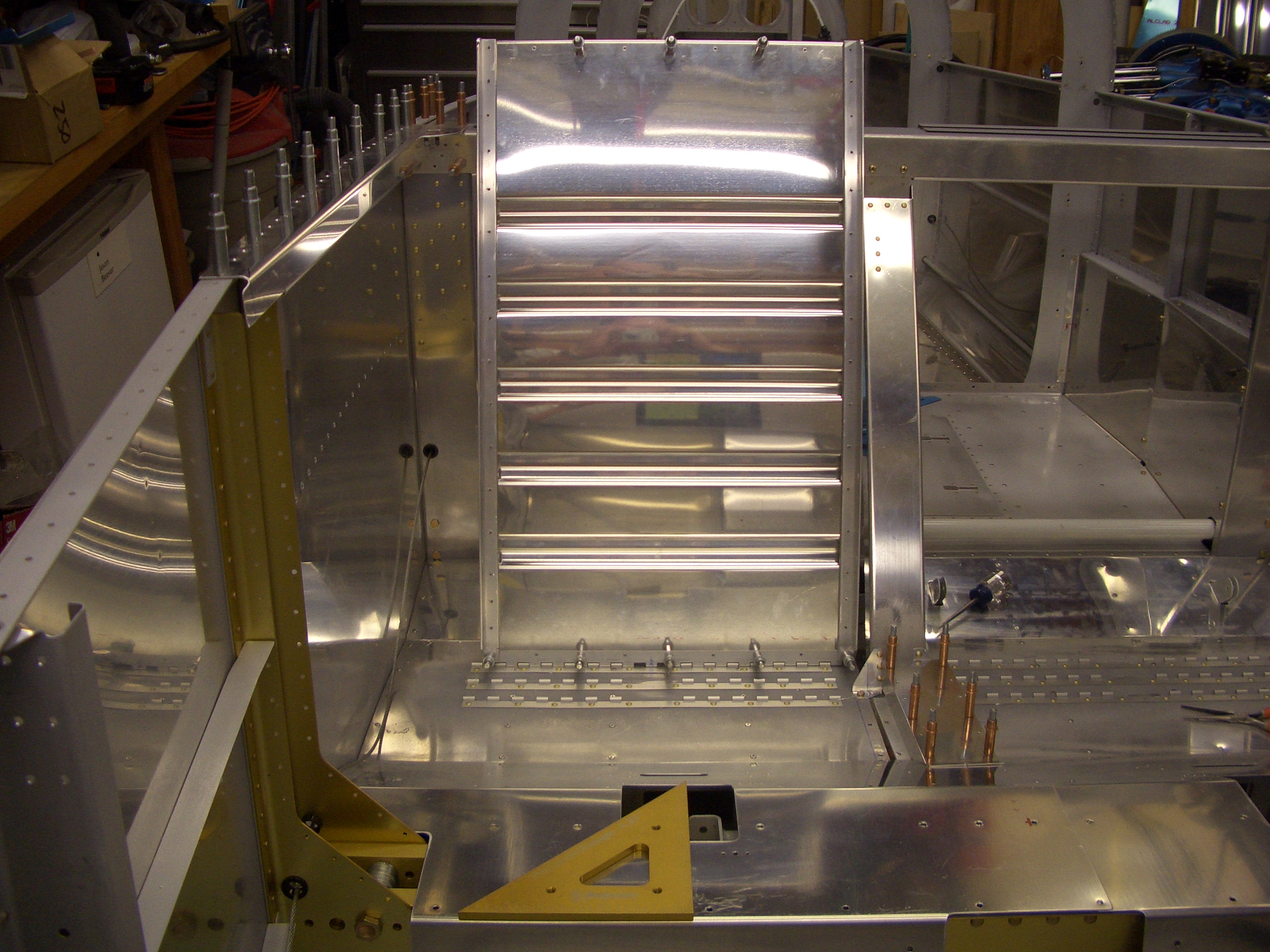
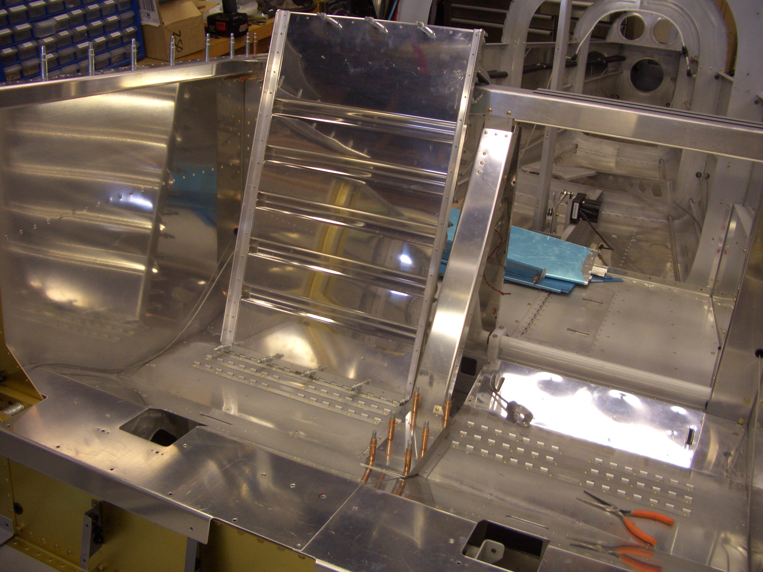
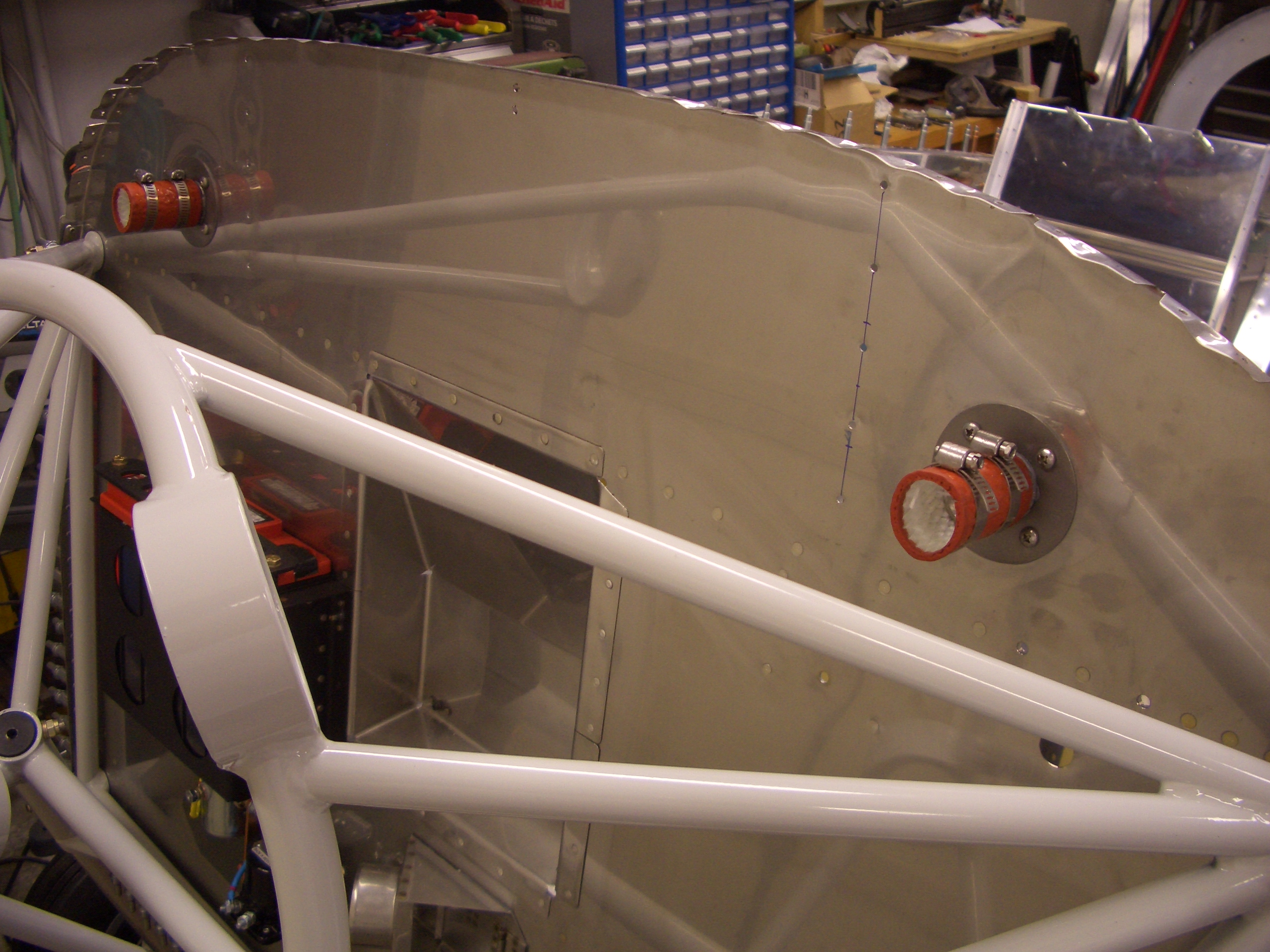
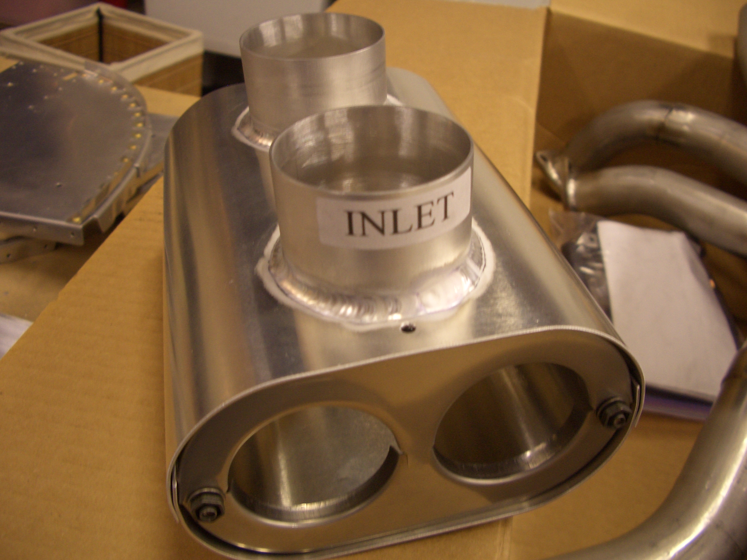
My order from Avery Tools included a couple of firewall pass-throughs from SafeAir1. These have a stainless steel tube with a spun flange so there are no sharp edges. I installed them with some 2000º fireproof sealant and then installed the outer fire sleeve and clamps.

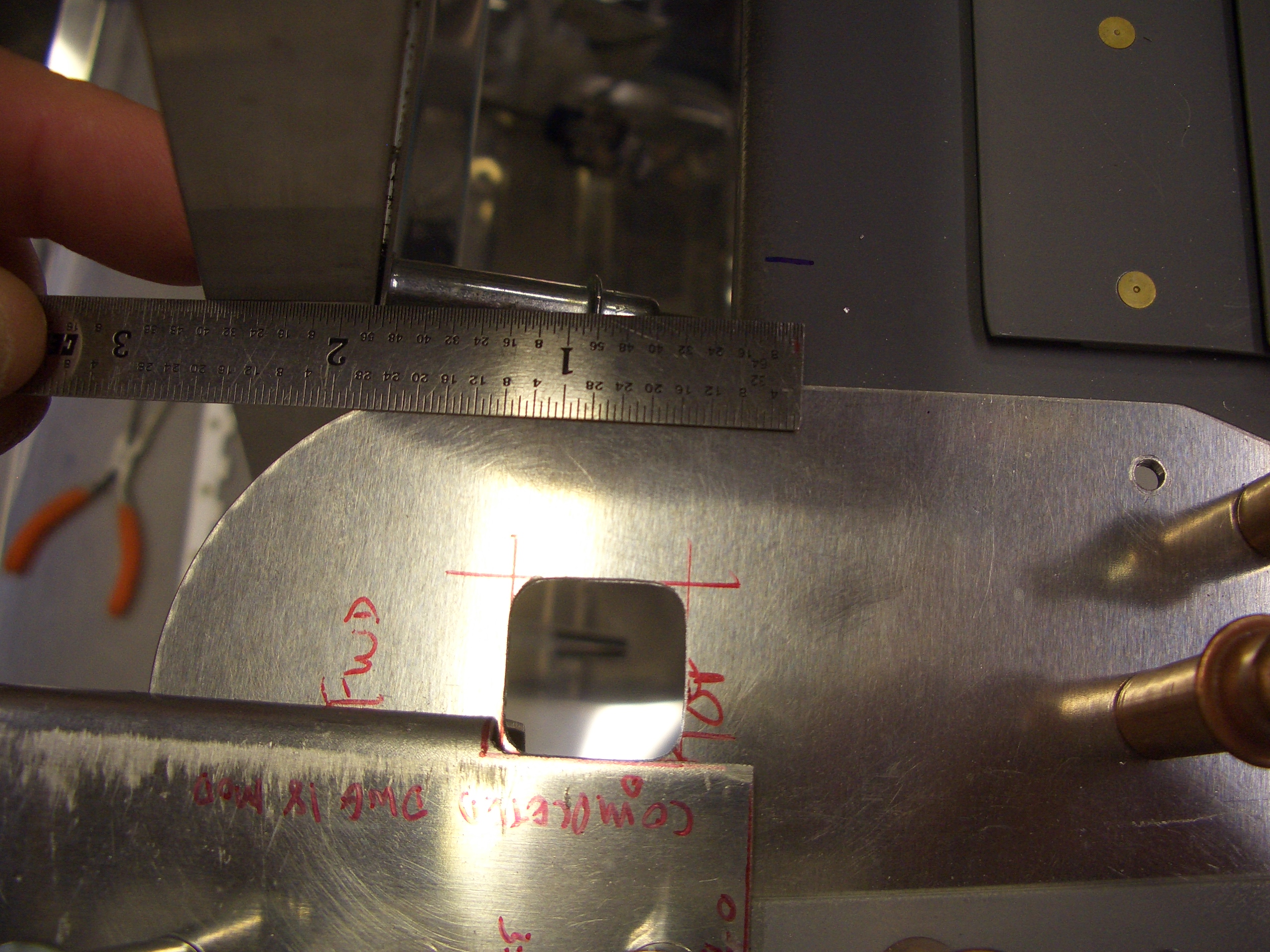
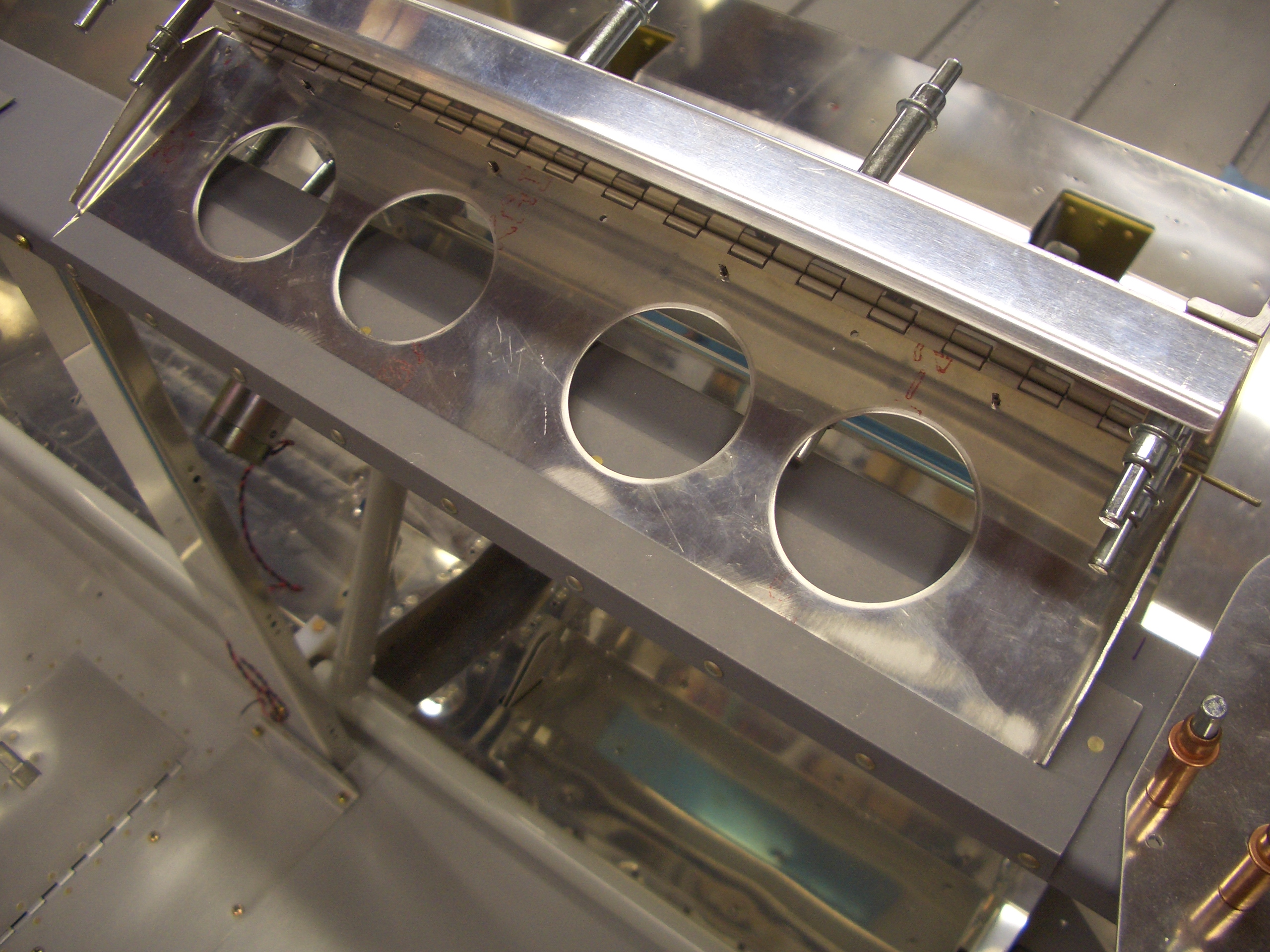
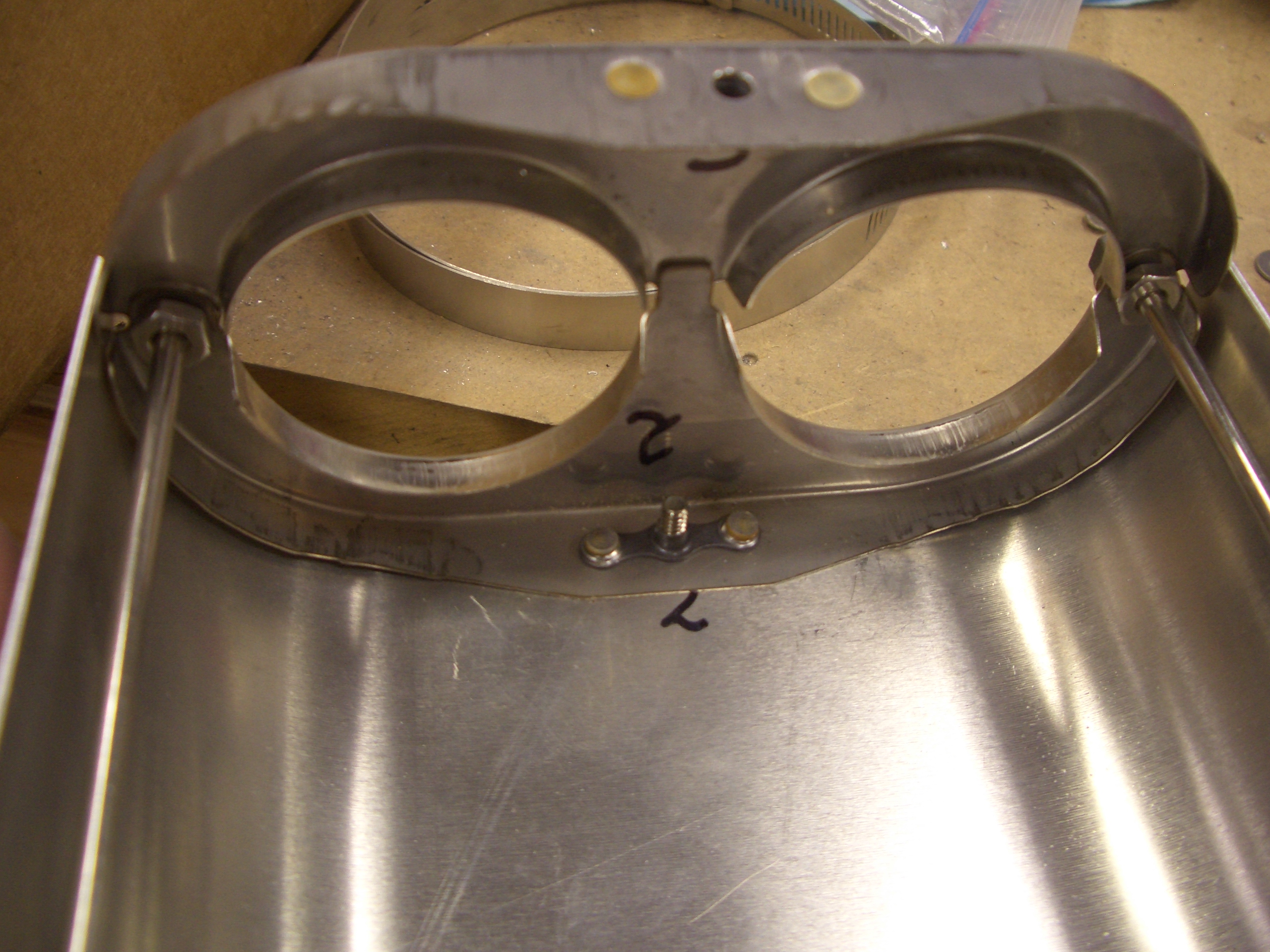
Here you can see through the pass-through. These each provide a 1″ opening for all of the wires that need to penetrate the firewall. I’ll use the one on the right side for all of the large power wires and the one of the left for all of the engine sensors. After the wires are installed, they’re wrapped tight with another piece of fire sleeving and some silicone tape and then pushed into the tube. The outer piece of fire sleeve is then slipped in place and the clamps are tightened.

Seats, Oil Temperature Sensor

I finished fabricating the seat backs.  I still need to drill all the holes out to #30, but at least all of the fabrication is done.  My son just had to try it out.

I had to increase the angle of the bend for the upper seat adjustment mechanism so that it would slip into either of the slots in the upper seat support.  Here you can see the two different adjustment positions.  The seats can also be leaned all the way back so that the seats simply rest against the upper seat support.

I was not comfortable that the Dynon oil temperature sensor had no provision for safety wiring it to prevent it from backing out.  I purchased this tool to drill a hole in the sensor.  The sensor fits inside and is clamped in place with the black bolt on the right.  I drill is then run through the small hole on the top (the one surrounded by metal chips).

Here is the oil temp sensor fully torqued down and safety wired

Prepped Seats for Riveting, Canopy Seal Supports

My buddy Andre stopped by today and we drilled all of the seat back rivets out to #30 and then deburred all of the seat components.  We also deburred the forward ribs.

I got started fabricating the outboard canopy seal supports.  These require laying out for rivet holes and cutting notches so that these can be curved to follow the curve of the forward edge of the canopy.

Canopy Seal Support Angles

I finished fabricating and drilling the outboard canopy seal support angles.  These will support pieces of weatherstripping that the front edge of the canopy will close down against.

Here you can see that the seal support angle sits 1/8″ below the flange of the subpanel.  This provides a gap for the weatherstipping.

Worked on Forward Fuselage and Canopy Decks

Because I’m going with the Dynon SkyView system, the aft end of the forward fuselage ribs need to be cut off.  I will move these over a bit and mount them between the SkyView screens and the radio stack.

I deburred and dimpled the holes in the firewall that attach these ribs using my pop rivet dimple dies.

Finally, I deburred and dimpled the forward canopy decks and countersunk the longerons.

The forward and aft canopy decks are tied together using rivets in these two holes.

Received Exhaust

I got my exhaust from Larry Vetterman today.  On Larry’s recommendation based on my engine and sump, I went with the four pipe system.  This is a little unusual for RV’s as it seems that most people go with the crossover exhaust which ties cylinders 1 and 2 together as well as cylinders 3 and 4 together resulting in two pipes exiting the cowl.  I’m glad I went with this system for a couple of reasons.  First, I just think it looks better with four pipes exiting the cowl.  Second, the cabin heat muff for the four pipe system passes the air over two pipes instead of one, so Larry claims that you get much more heat out of this system.  Here are the pipes as received from Larry.  The upper four pipes have the flanges on them which mount to the cylinders.  The lower four pipes have ball joints which gives the exhaust system some flexibility to prevent cracking.

Here is the cabin heat muff.

I loosely assembled the upper and lower sections for each cylinder.

The instructions call for using sheet metal screws to hole some of the parts together in the cabin heat muff.  The heat muff in our Cardinal is assembled this way and every time we open the cowl, there are a couple of screws missing.  The plans specify that you can optionally install nutplates, so I installed some K1000-06 nutplates and ordered some extra AN526C632-6 screws.

Here is the temporarily assembled heat muff.  The muff will surround the exhaust pipes from cylinders 1 and 3, and the air inlet and outlet are on the top.

Here’s the inside of the muff showing the nutplates on the top and bottom of the end caps and showing the rods that connect the two ends of the muff.  I’ll assemble this permanently once the exhaust is installed on the engine.

Finished Seat Backs

I primed and riveted together the seat backs today.  I’ll probably shoot this with the lighter of the two interior colors I’m using, but I only plan on using these when I have on chutes, so I’m not sure.  For the regular interior, I’ll be going with the Classic Aero Designs Aviator Seat Package which has an integrated seat back.

I also primed and riveted the center tunnel cover.  This will be covered by carpet, so I’ll just leave this primed.