Primed Tailcone Components and Started Assembly

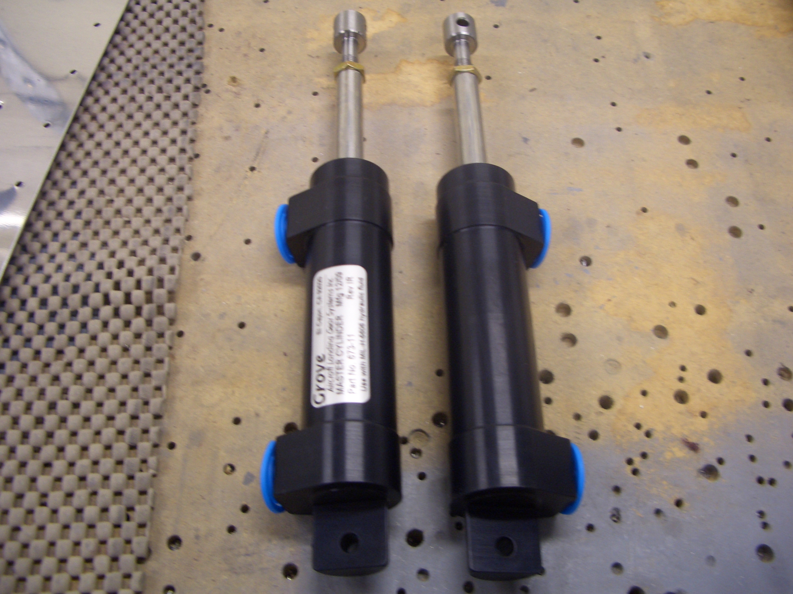
I received my Grove Aircraft master cylinders in the mail today.  I decided to upgrade from the stock Matco master cylinders because people have had issues with them sticking.  It appears that the issue can be addressed with external springs, but I don’t really like the way those look.  Also, I heard such good things about the Grove cylinders that they seemed like the better choice.  These have internal springs, so there should be no issue with them not extending fully when brake pressure is released.

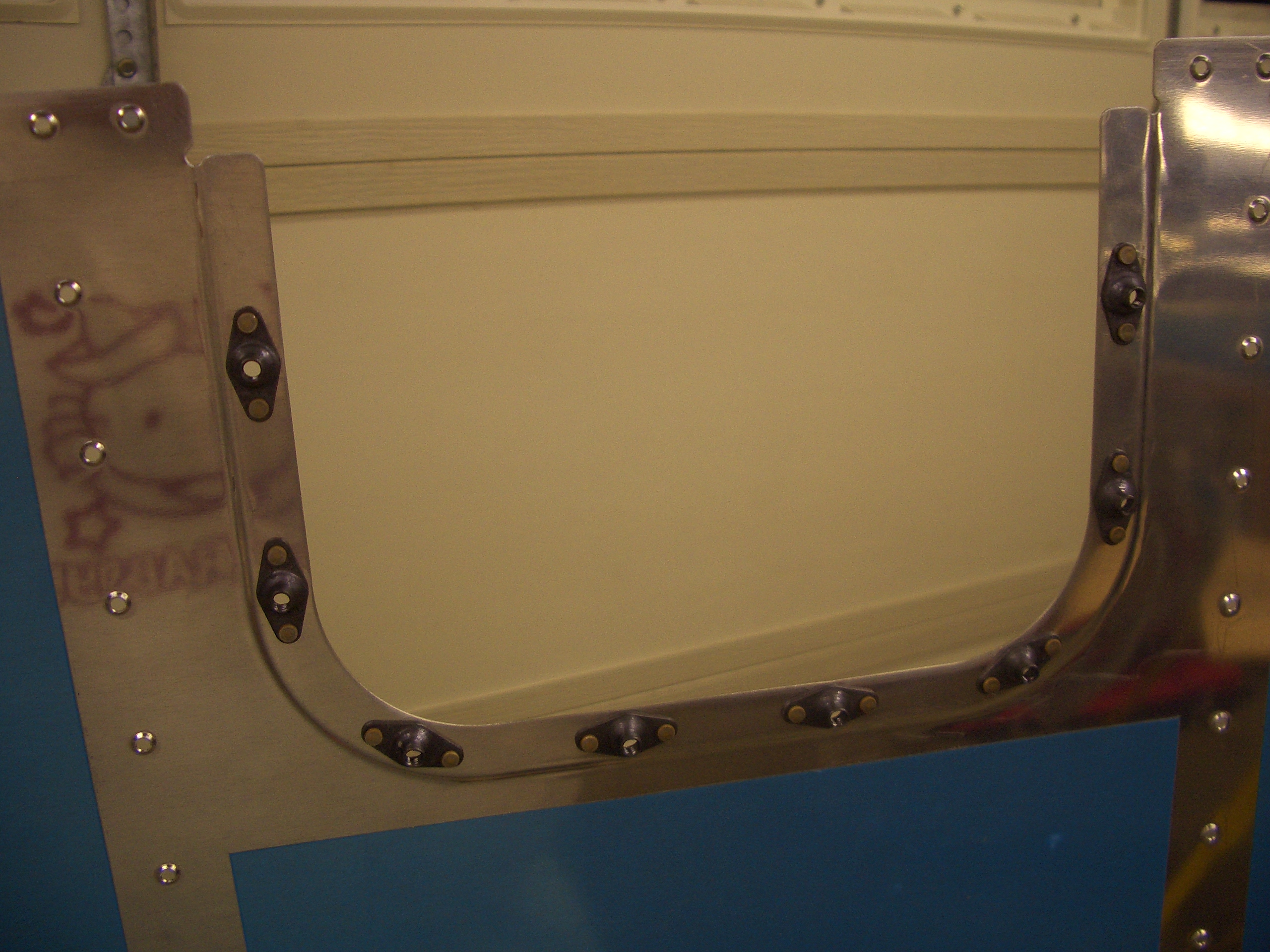
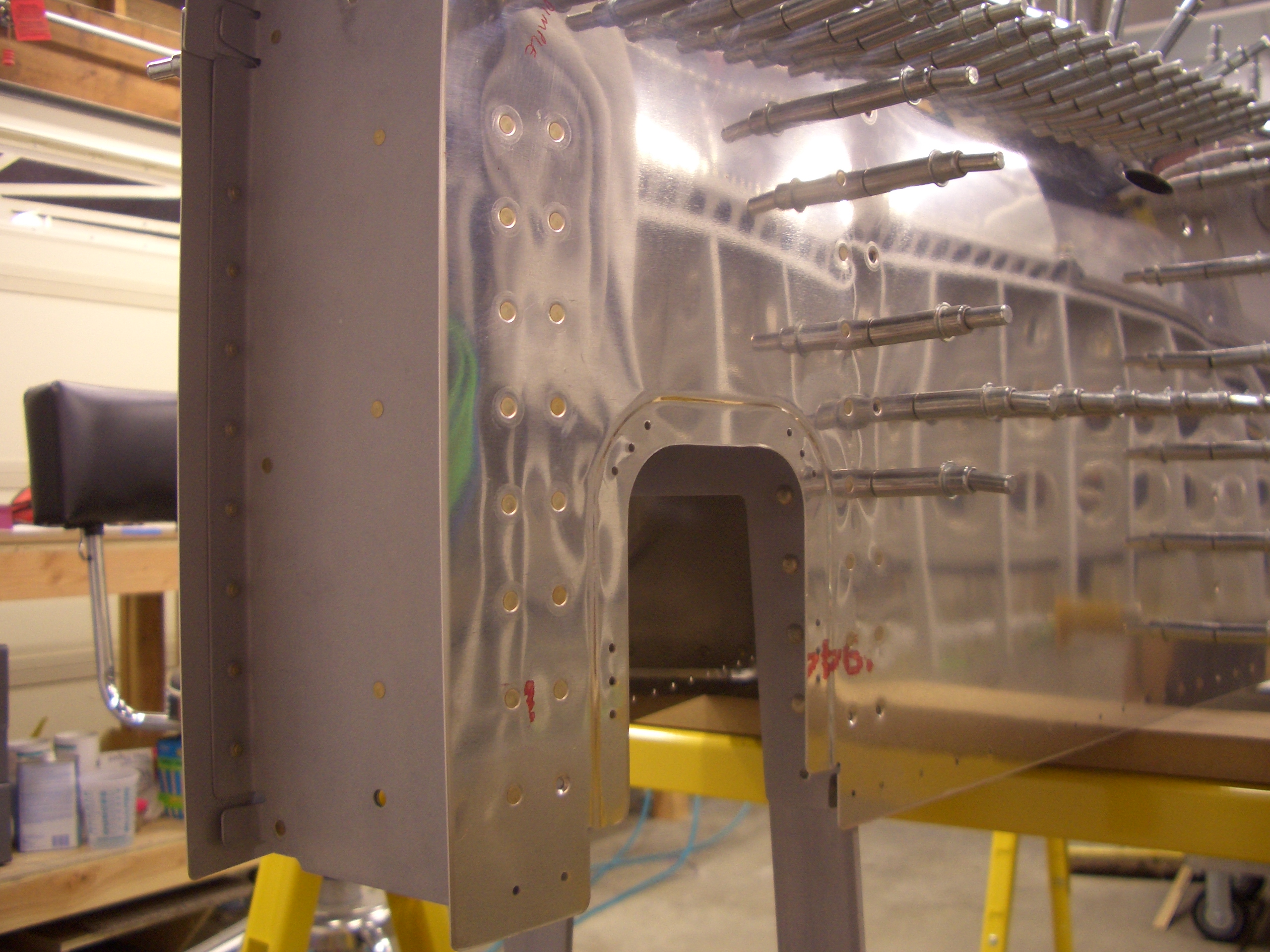
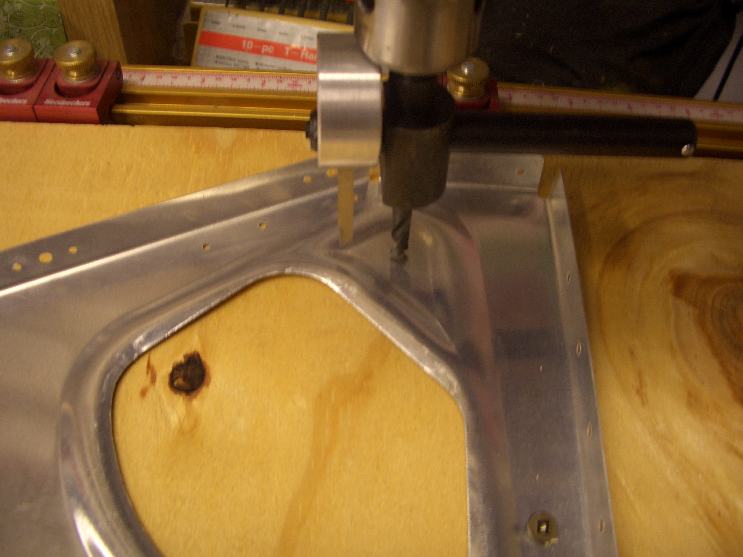
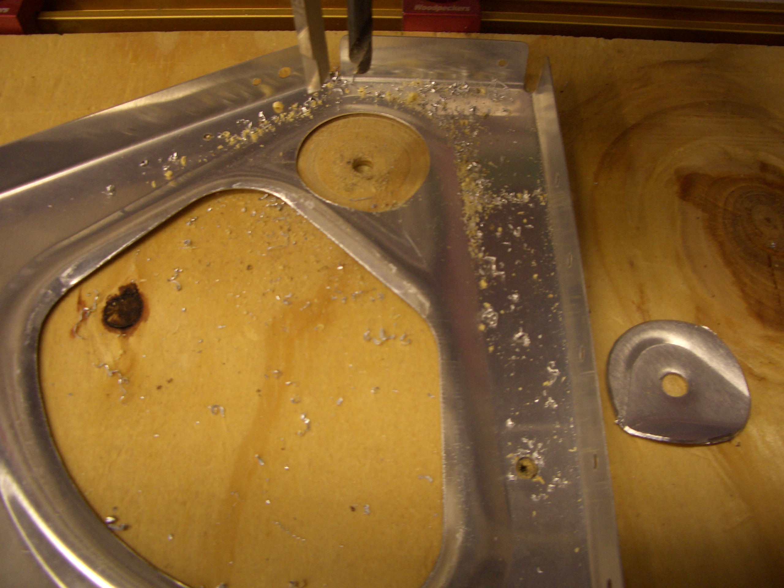
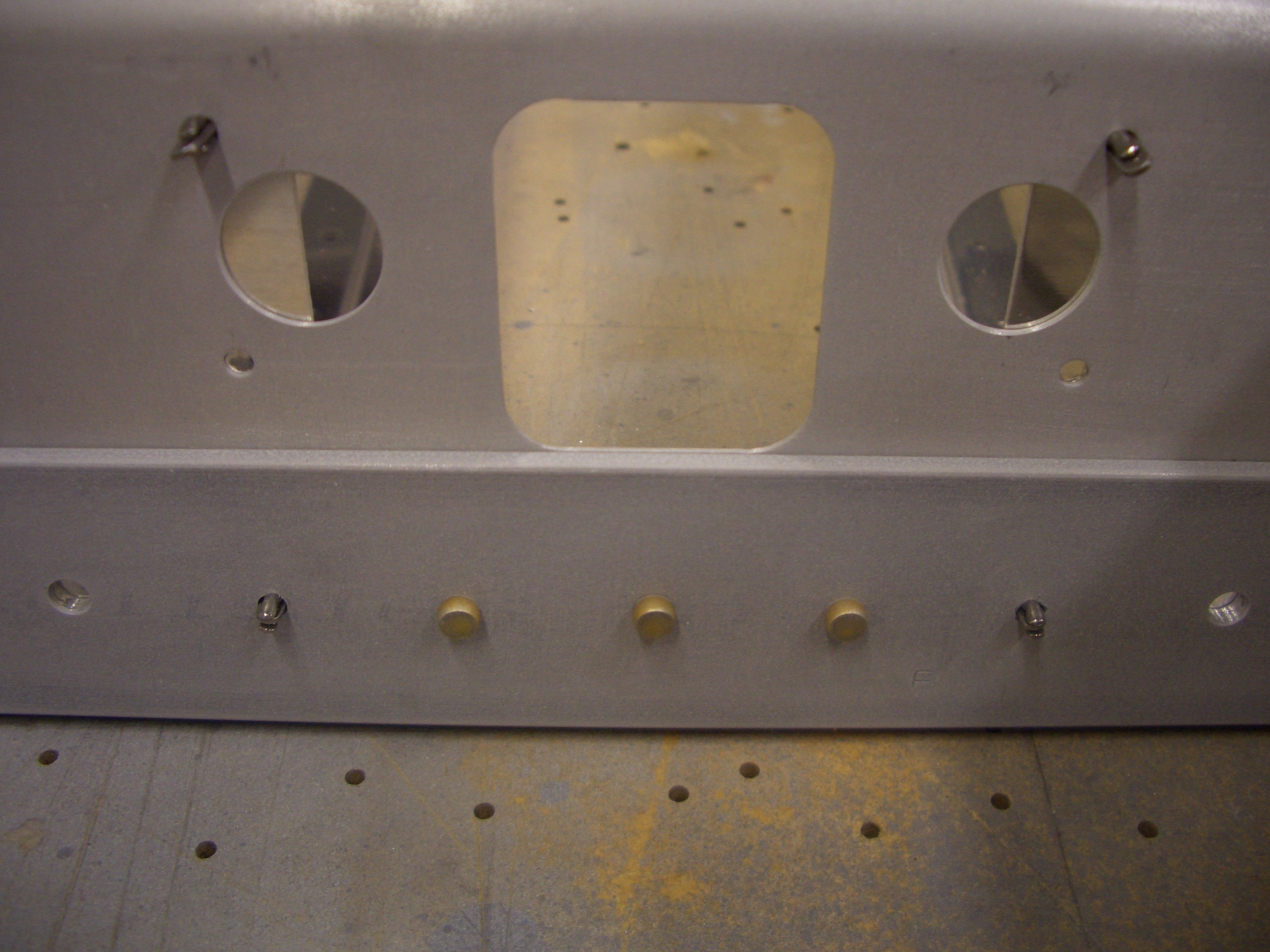
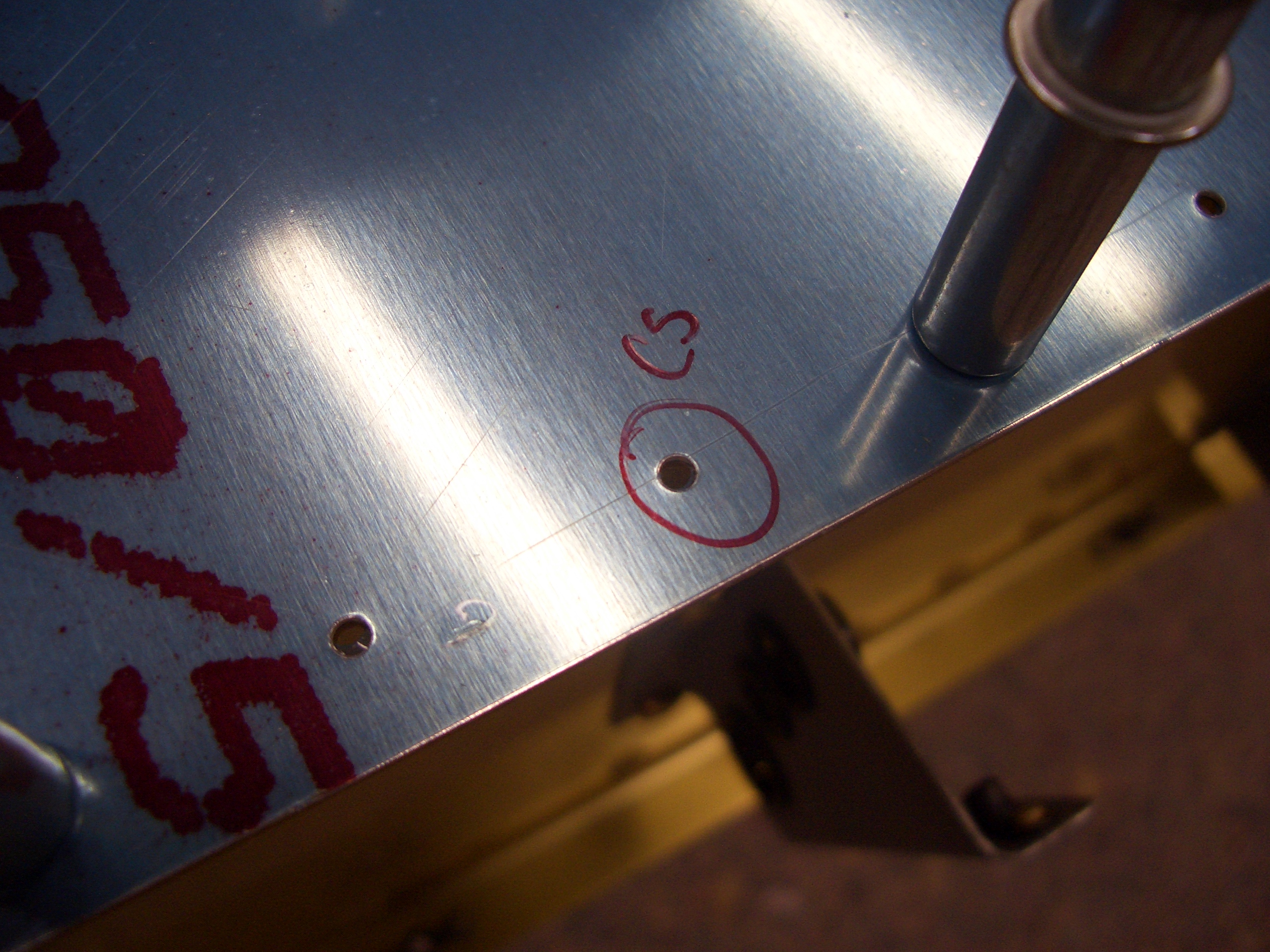
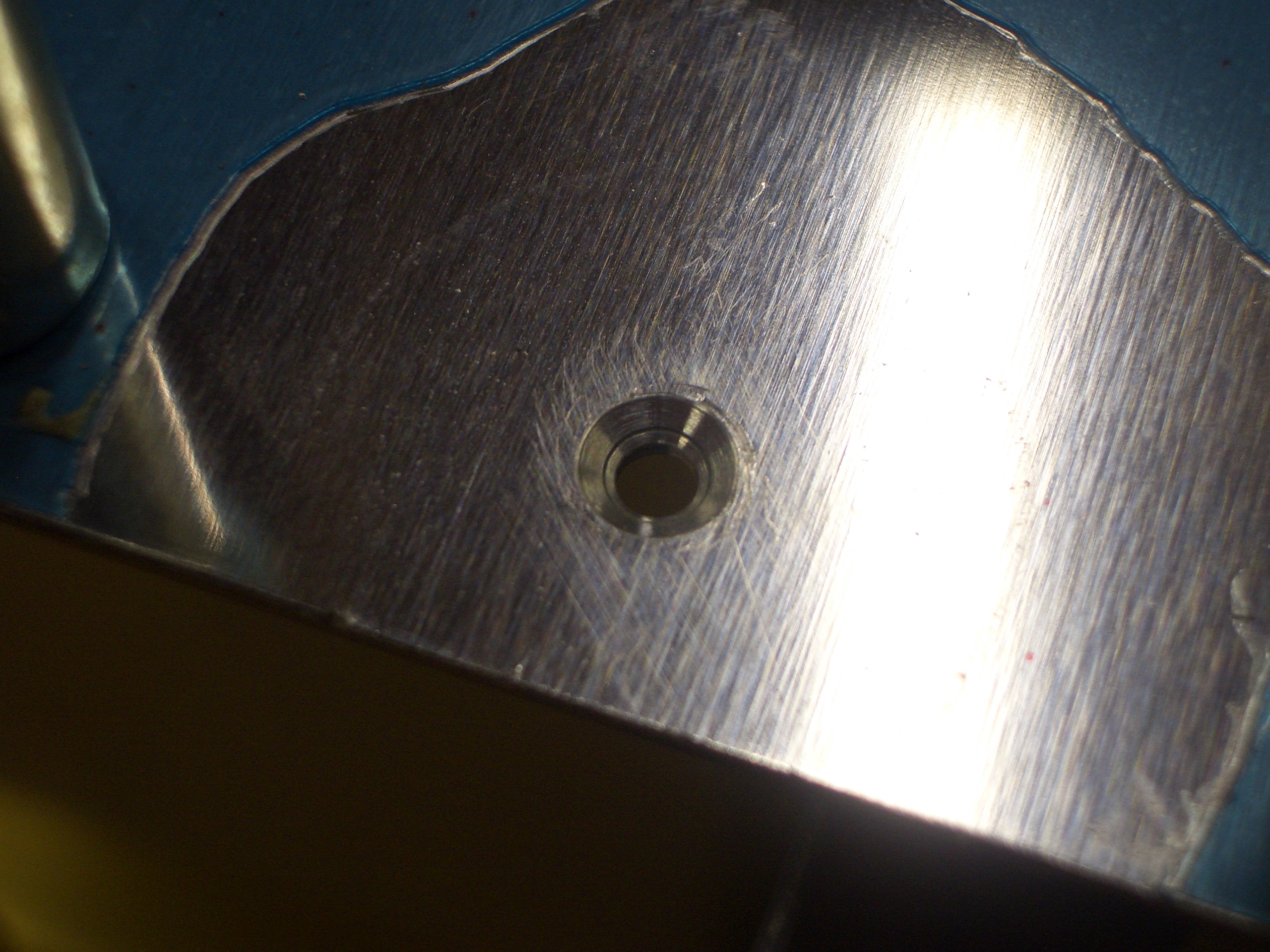
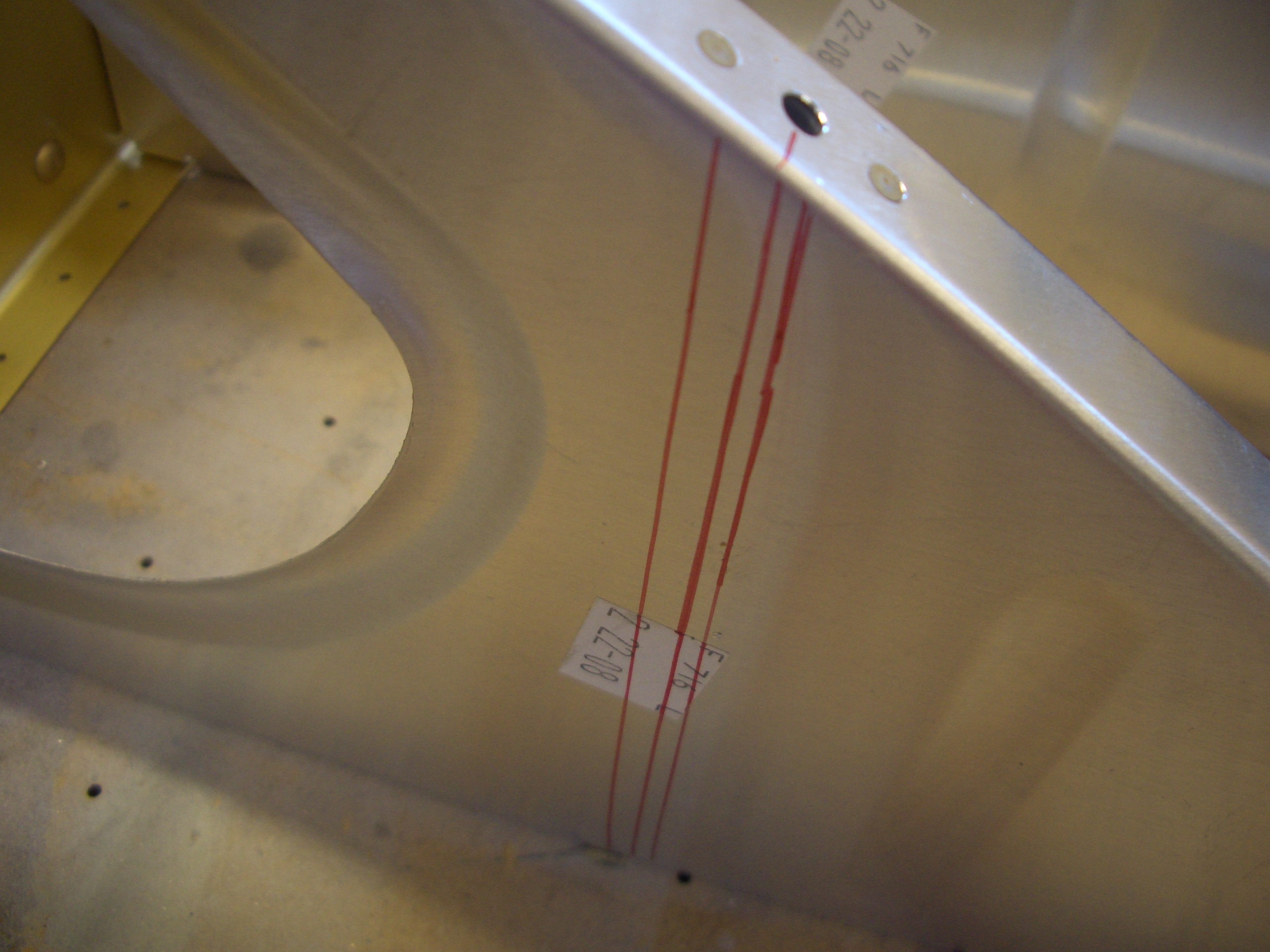
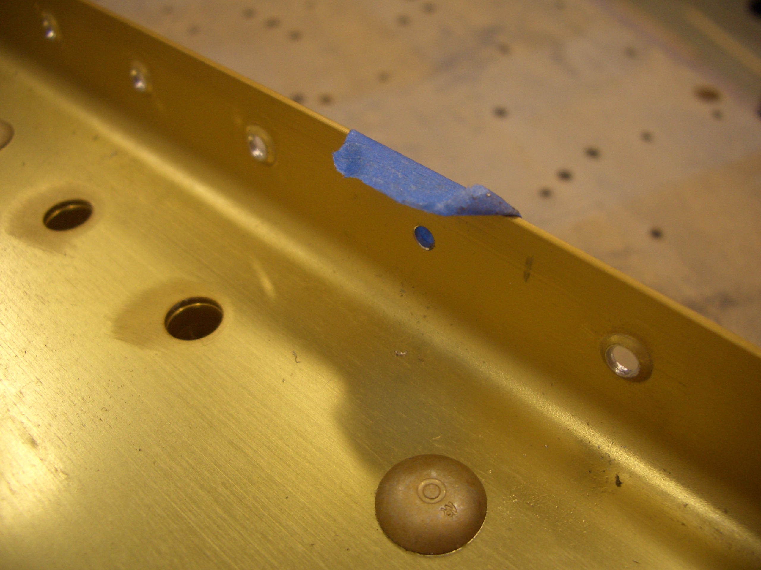
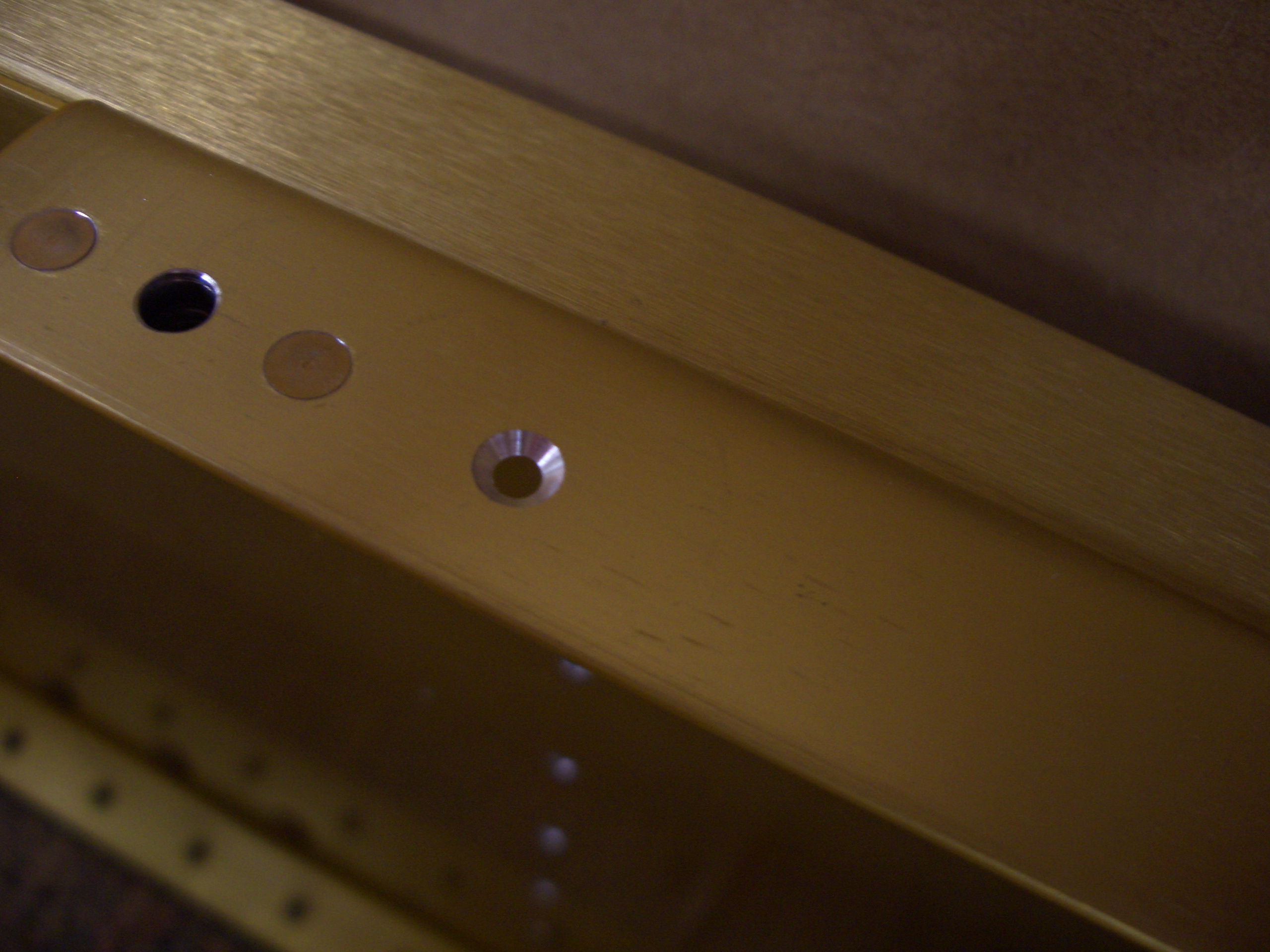
Before reassembling the tailcone, I took care of one additional task that would be tough if I waited until later.  I drilled the holes next to the rudder cable exit holes out to #19 and dimpled for a #8 screw.  This will be used to attach an adel clamp to hold the rudder cable guide.

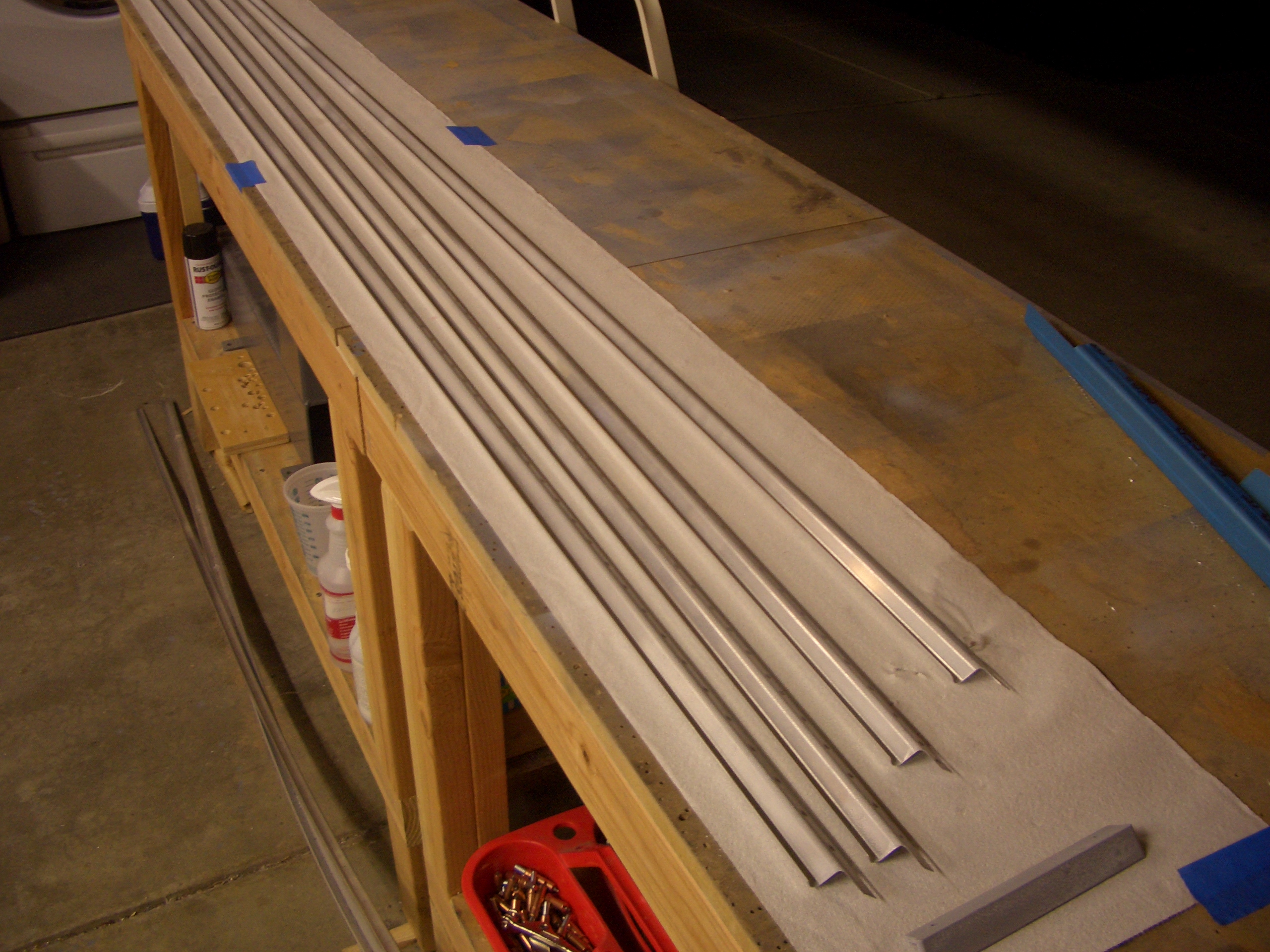
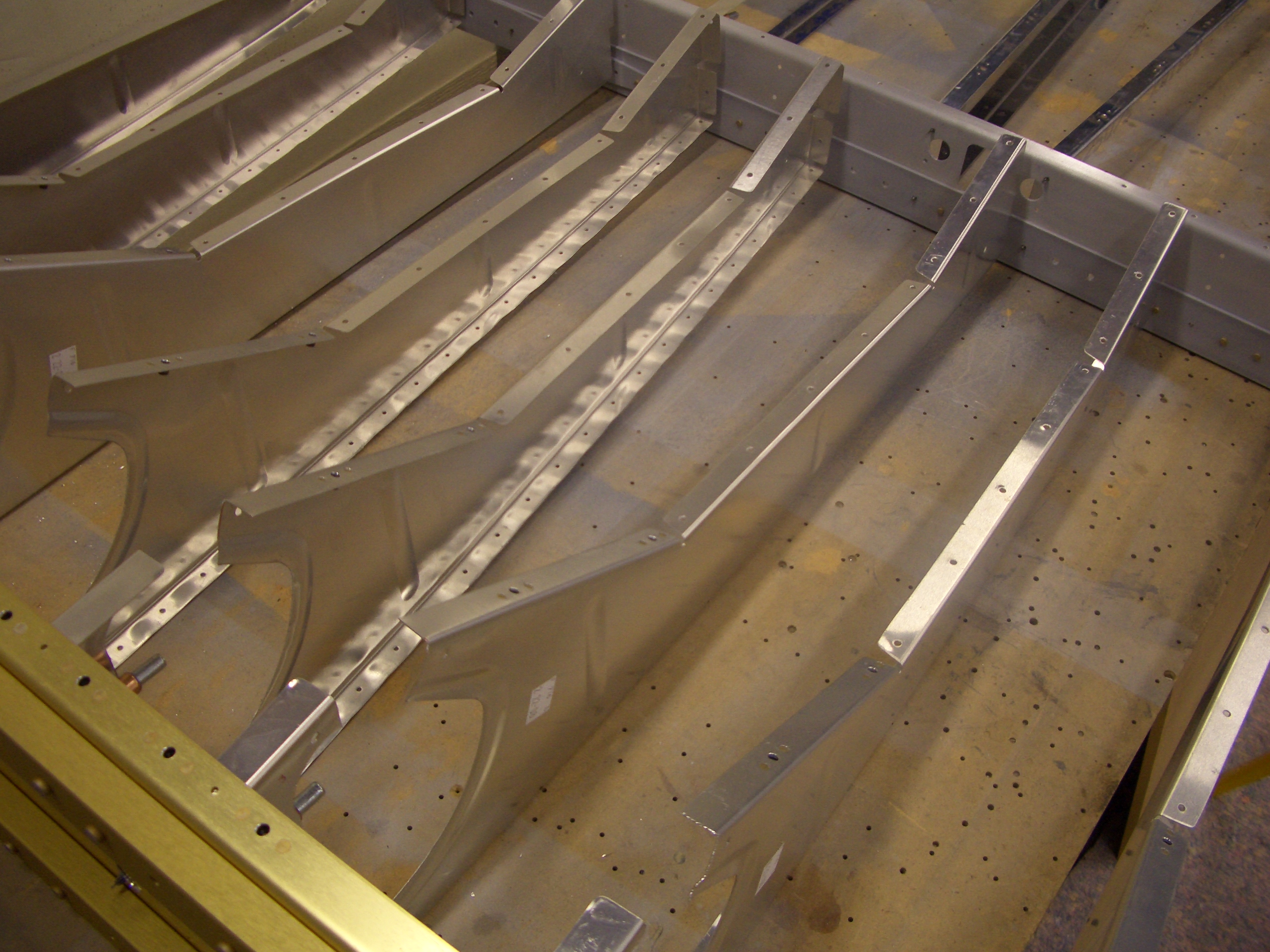
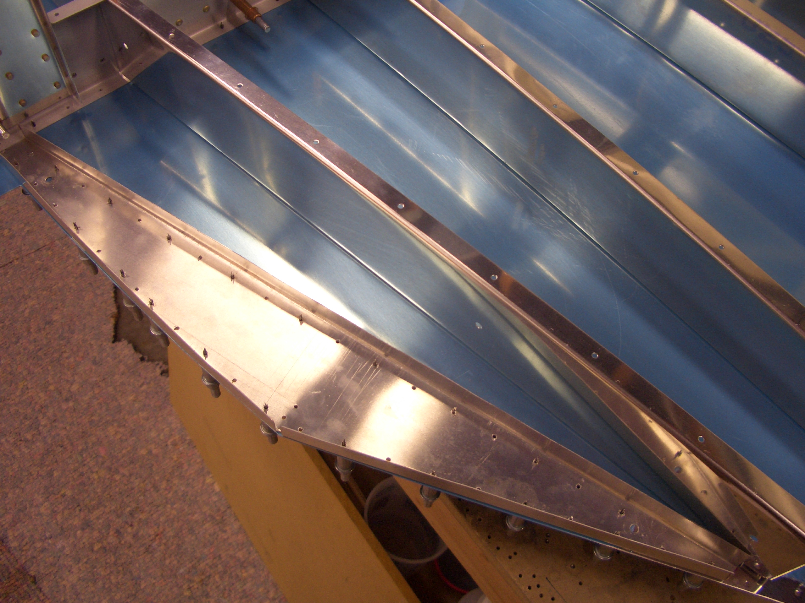
I primed all of the bulkhead and stringer seams since these got somewhat scratched up during the drilling.

I also primed the rest of the components for the tailcone.

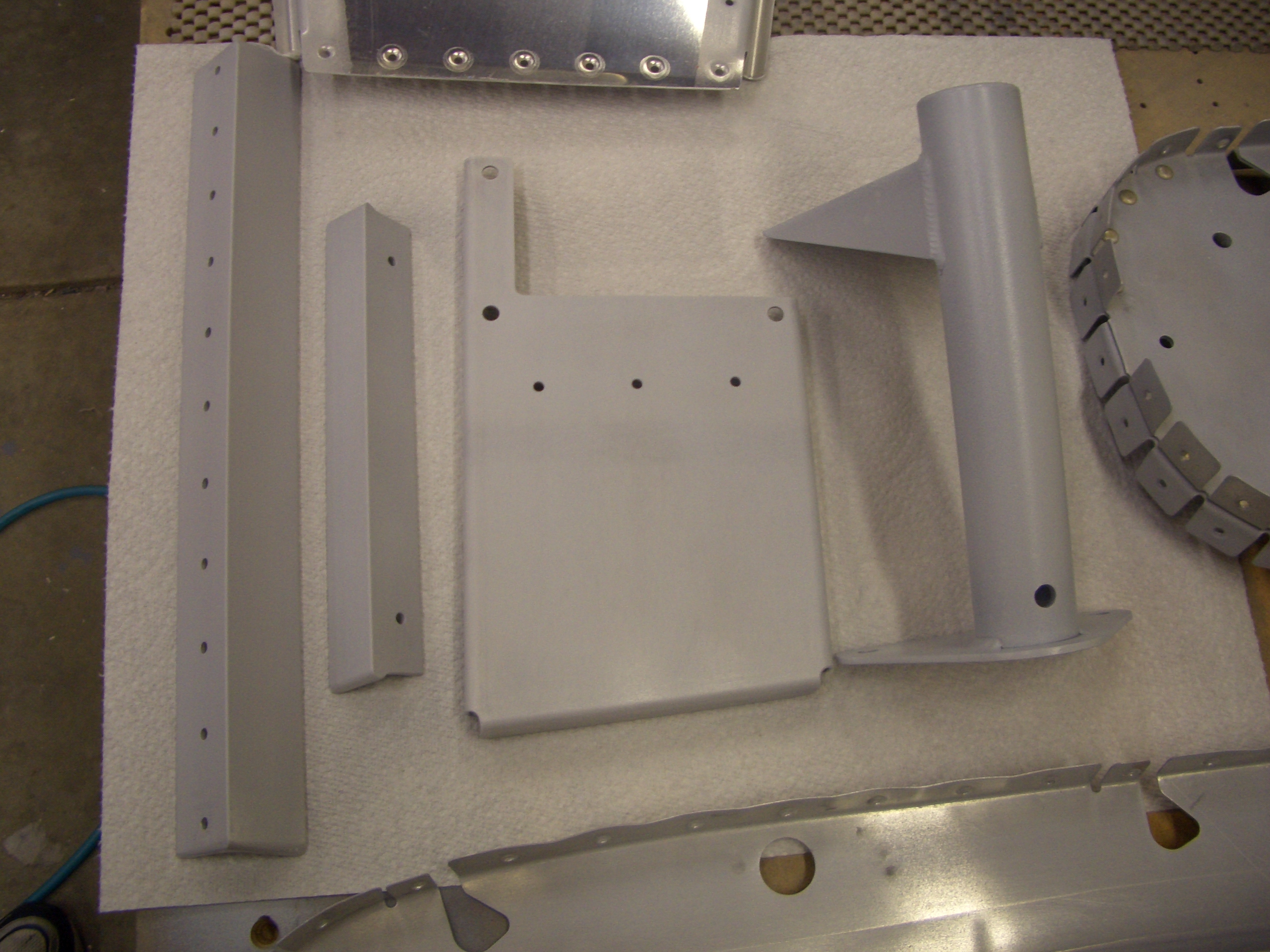
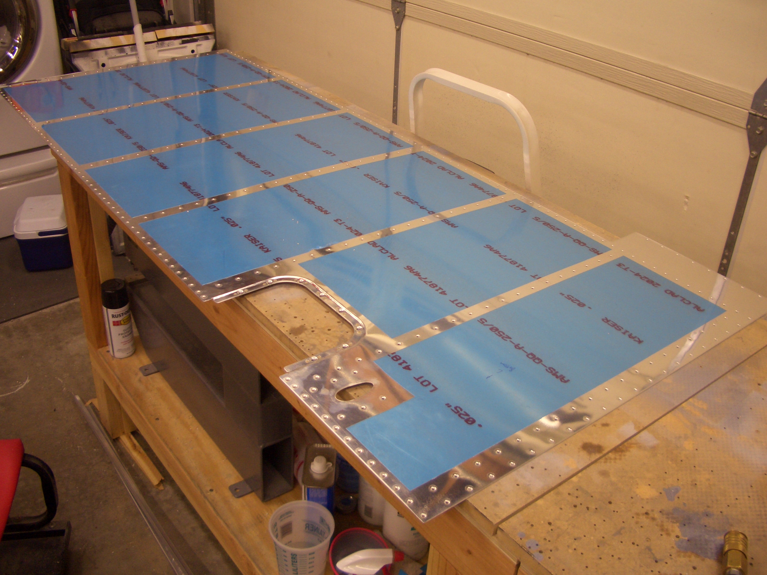
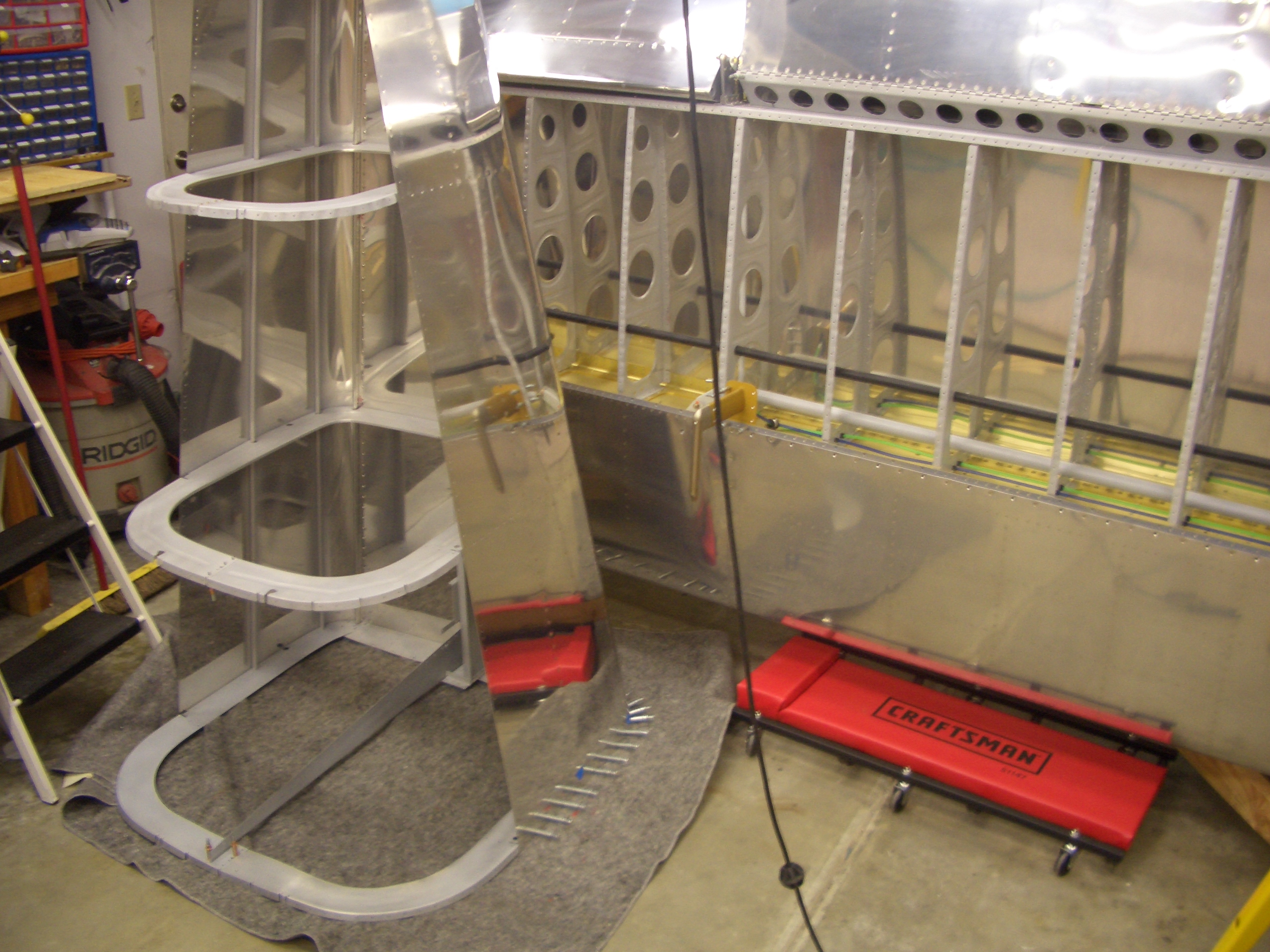
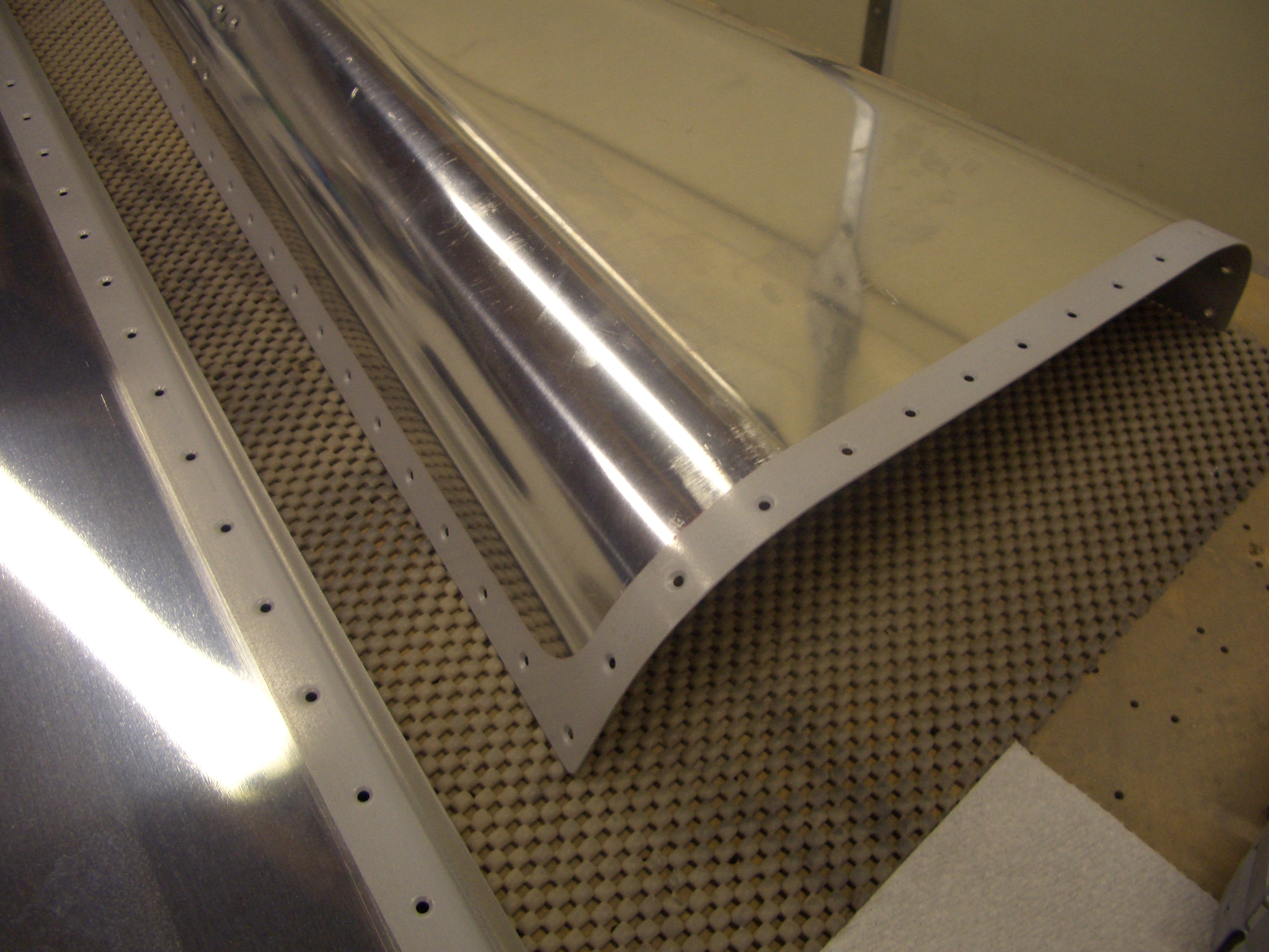
Since these are the lowest seams in the fuselage, I wanted to prime the overlap areas in case any water gets trapped there.  I also primed the entire inside of the tail skin.

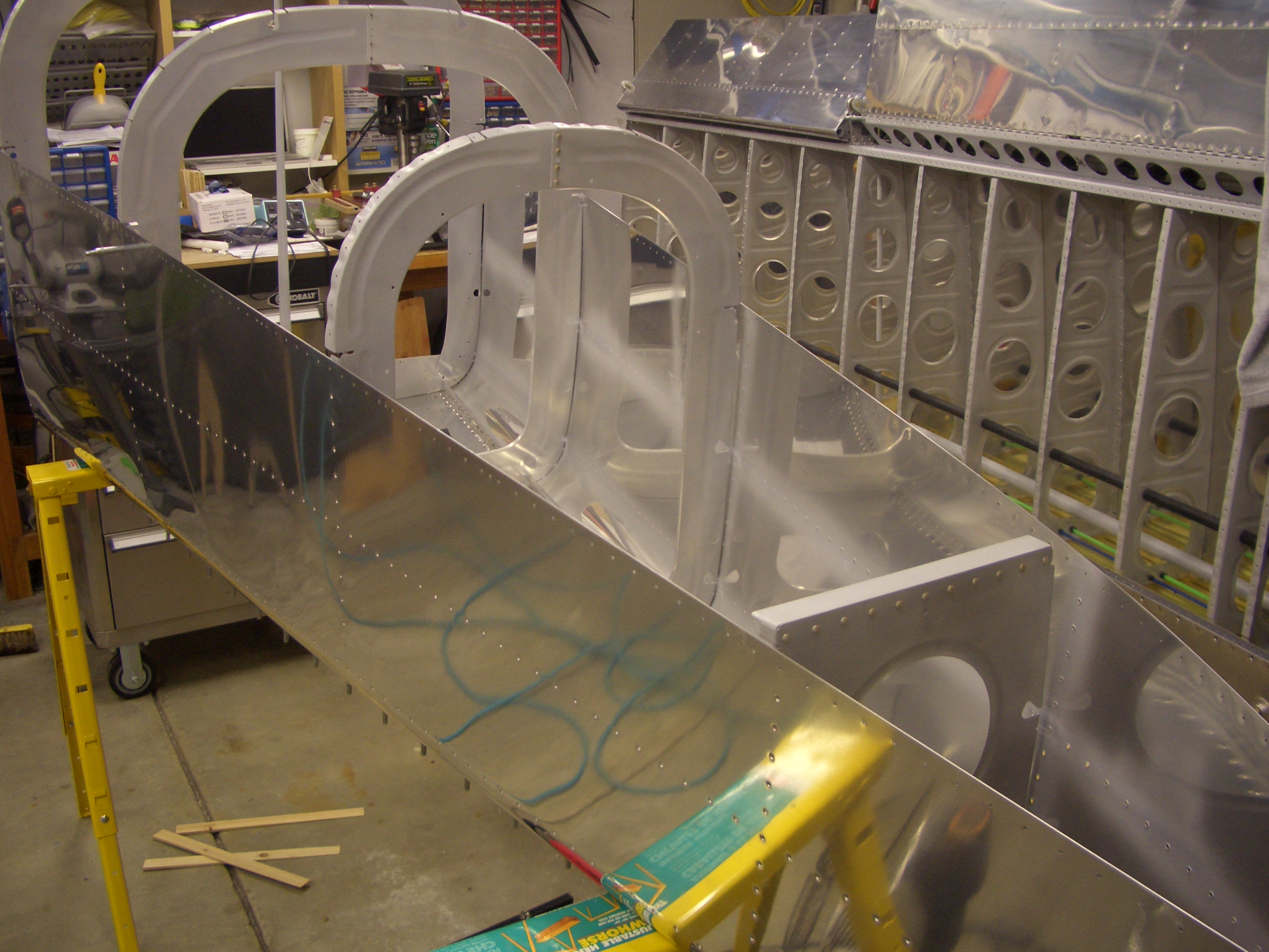
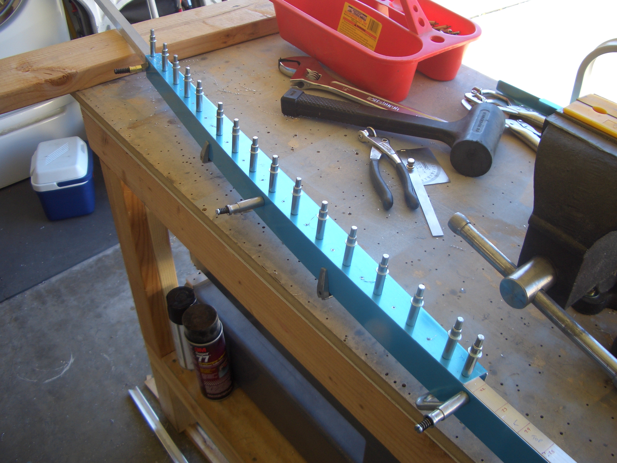
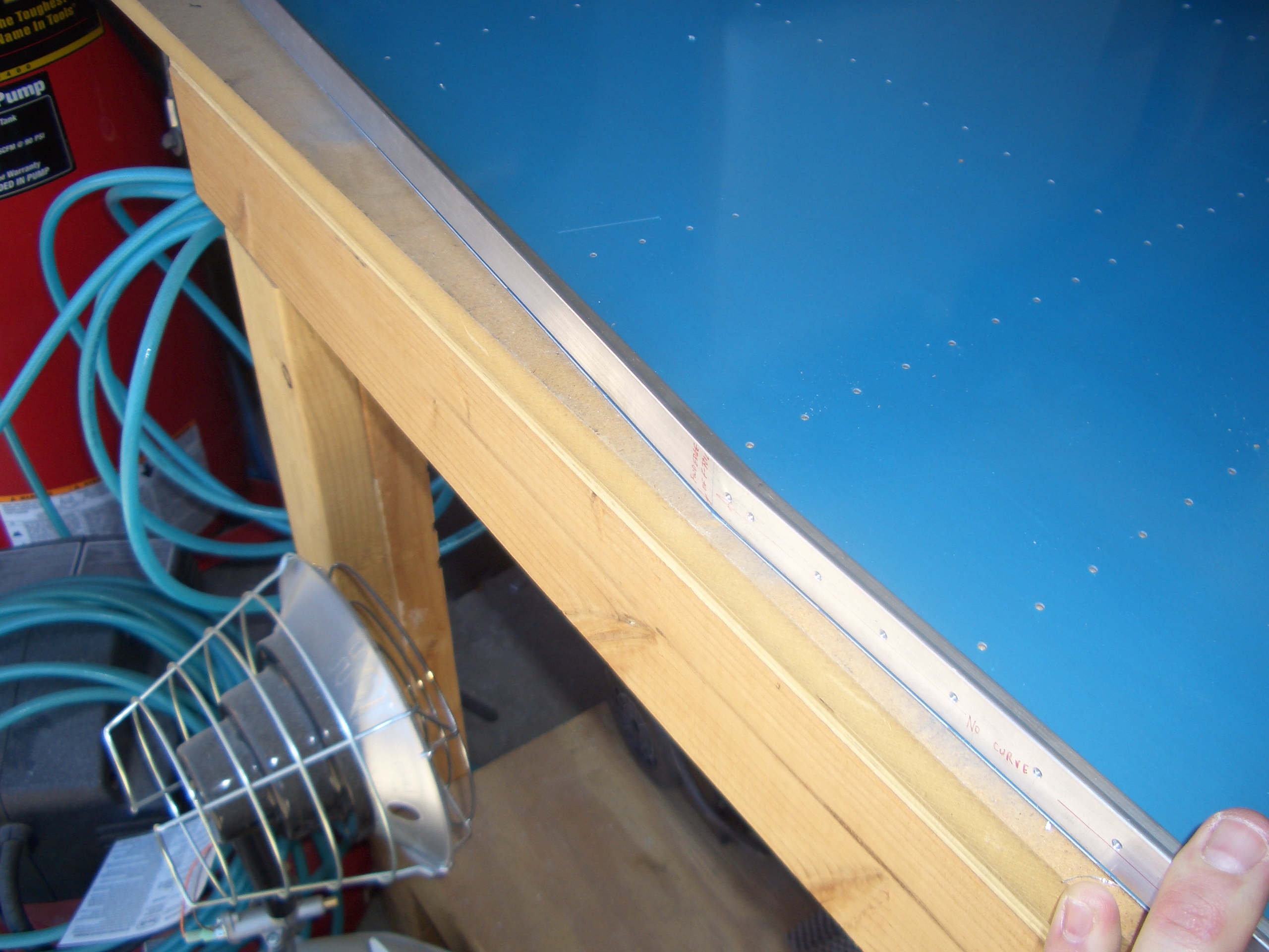
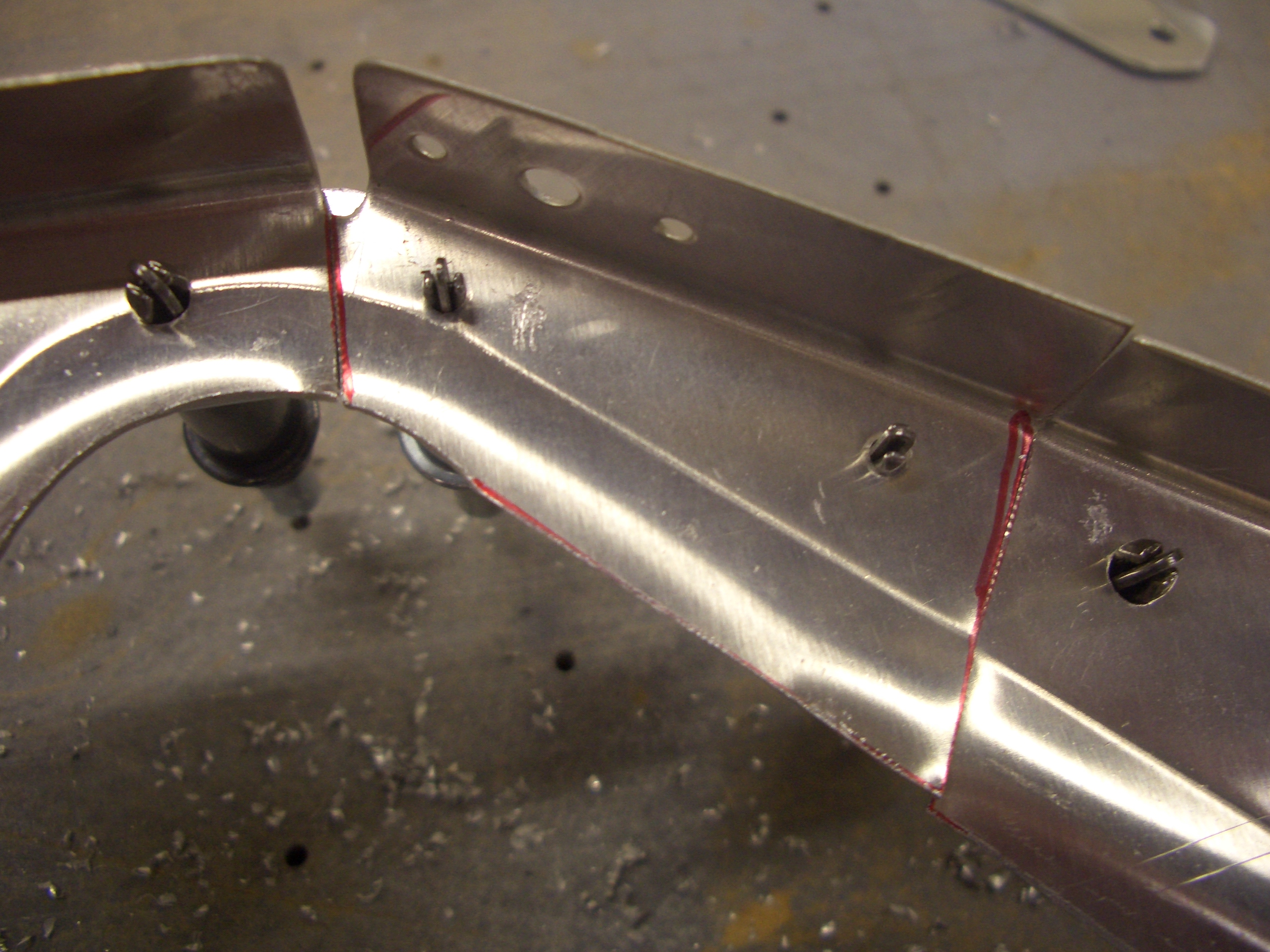
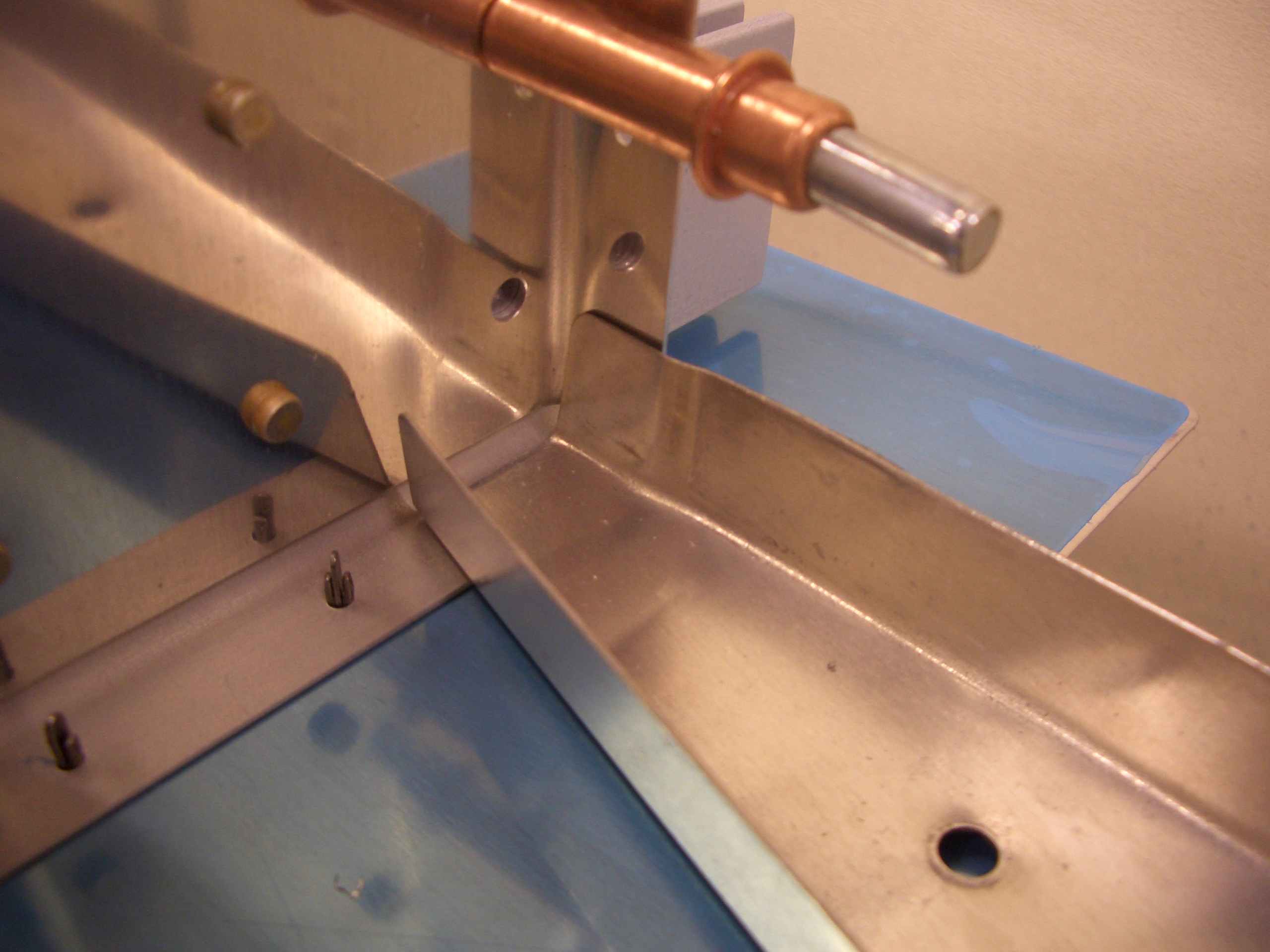
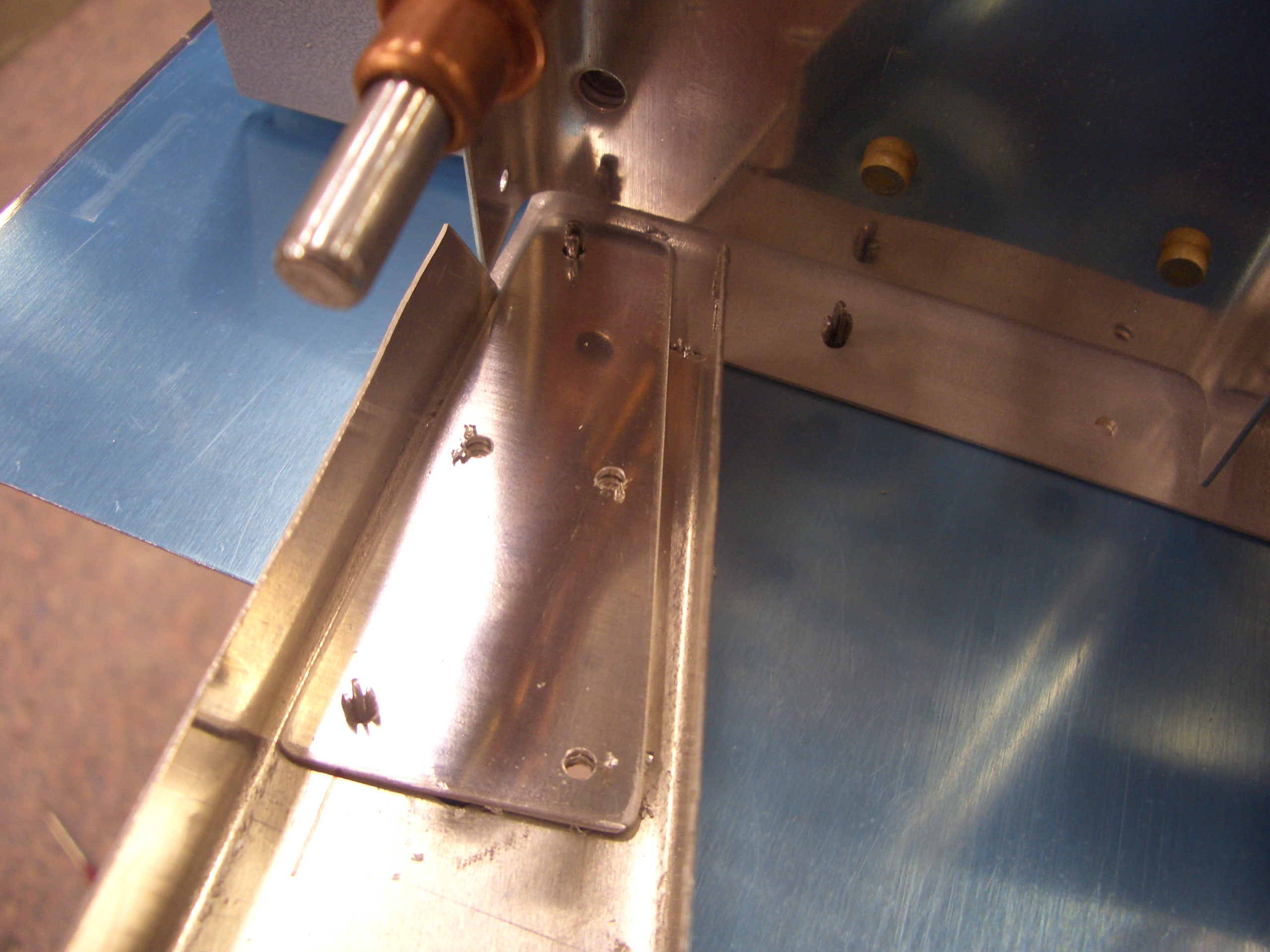
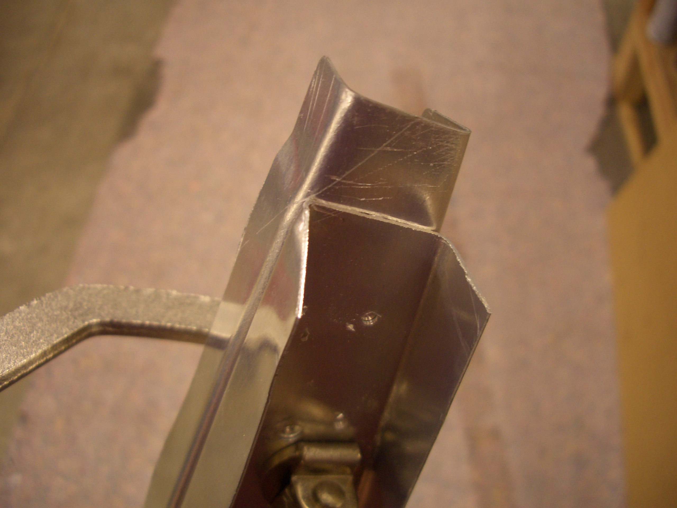
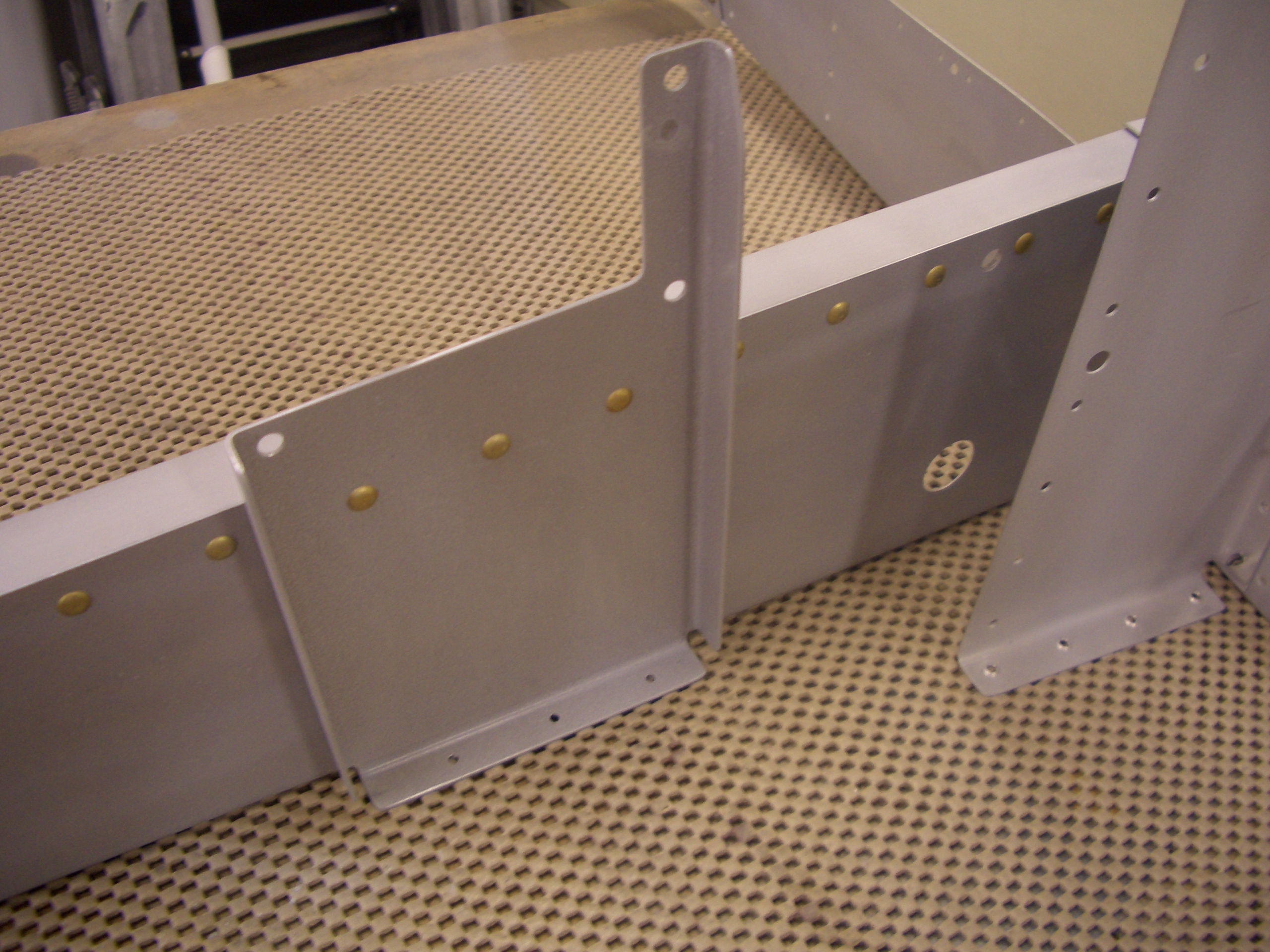
The top angle can now be riveted to the F-710 bulkhead.

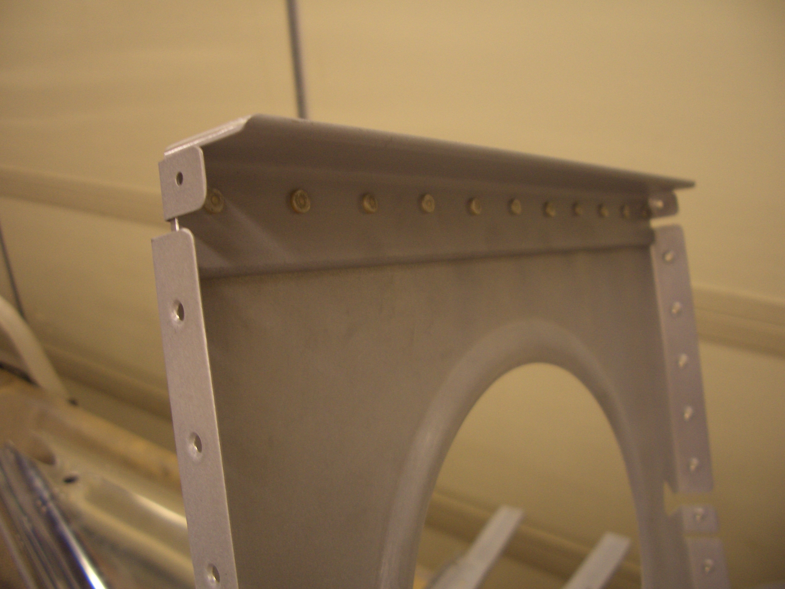
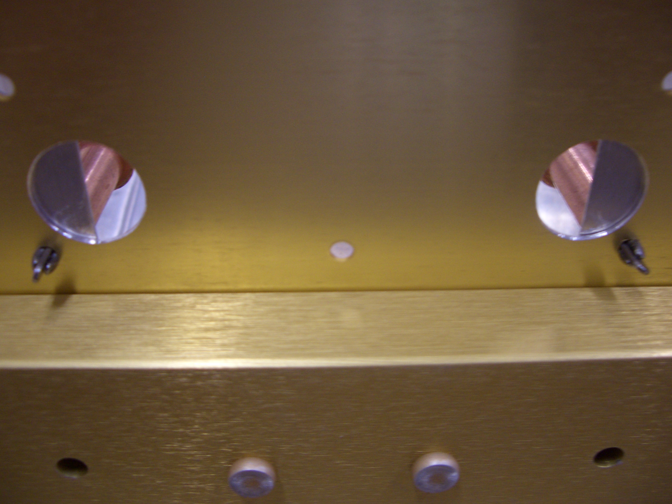
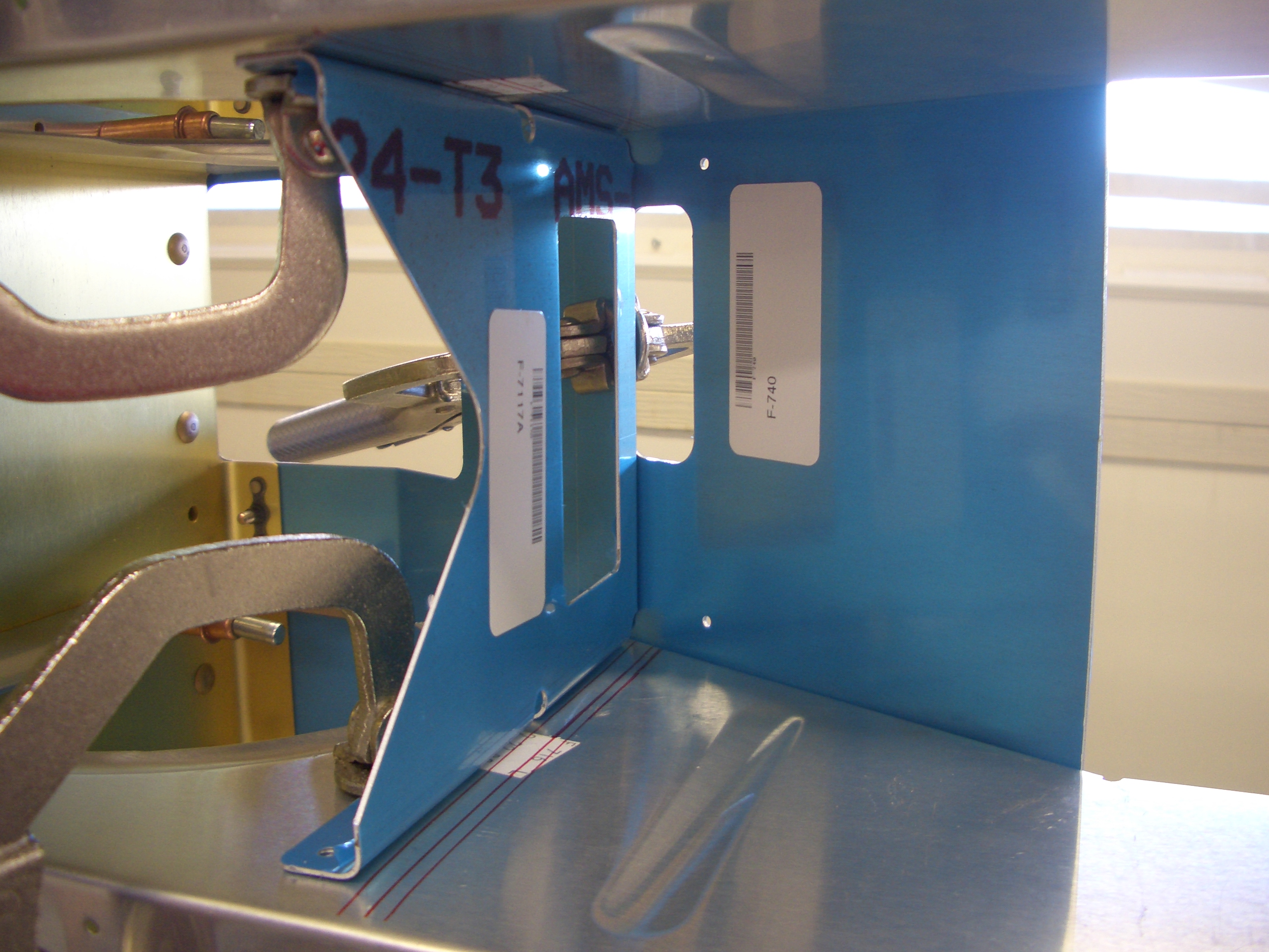
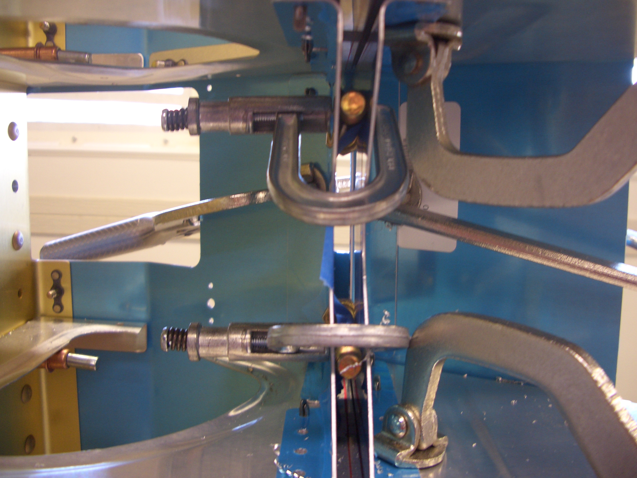
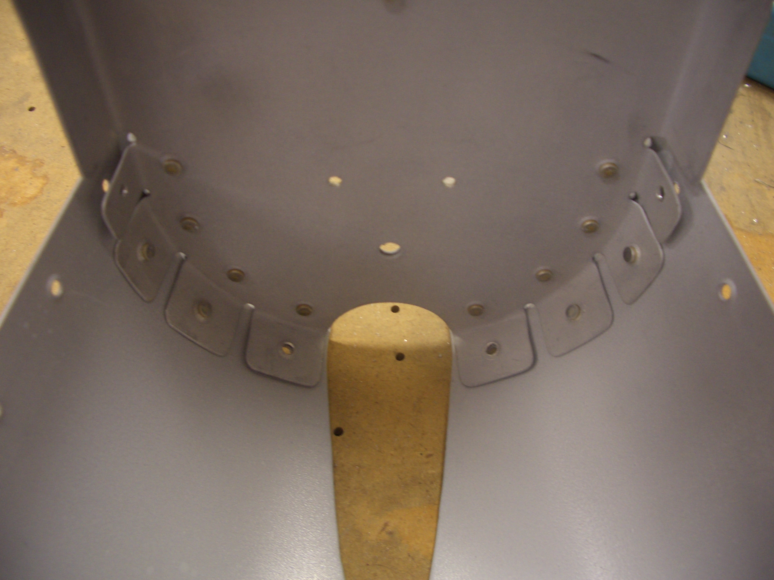
And F-712 can be riveted to the tail skin.  These rivets were a little tricky to set, and I ended up drilling out two of them and replacing them.  Since these flanges have an acute angle to the web, using the 4″ no-hole yoke with its thin nose made these easier.

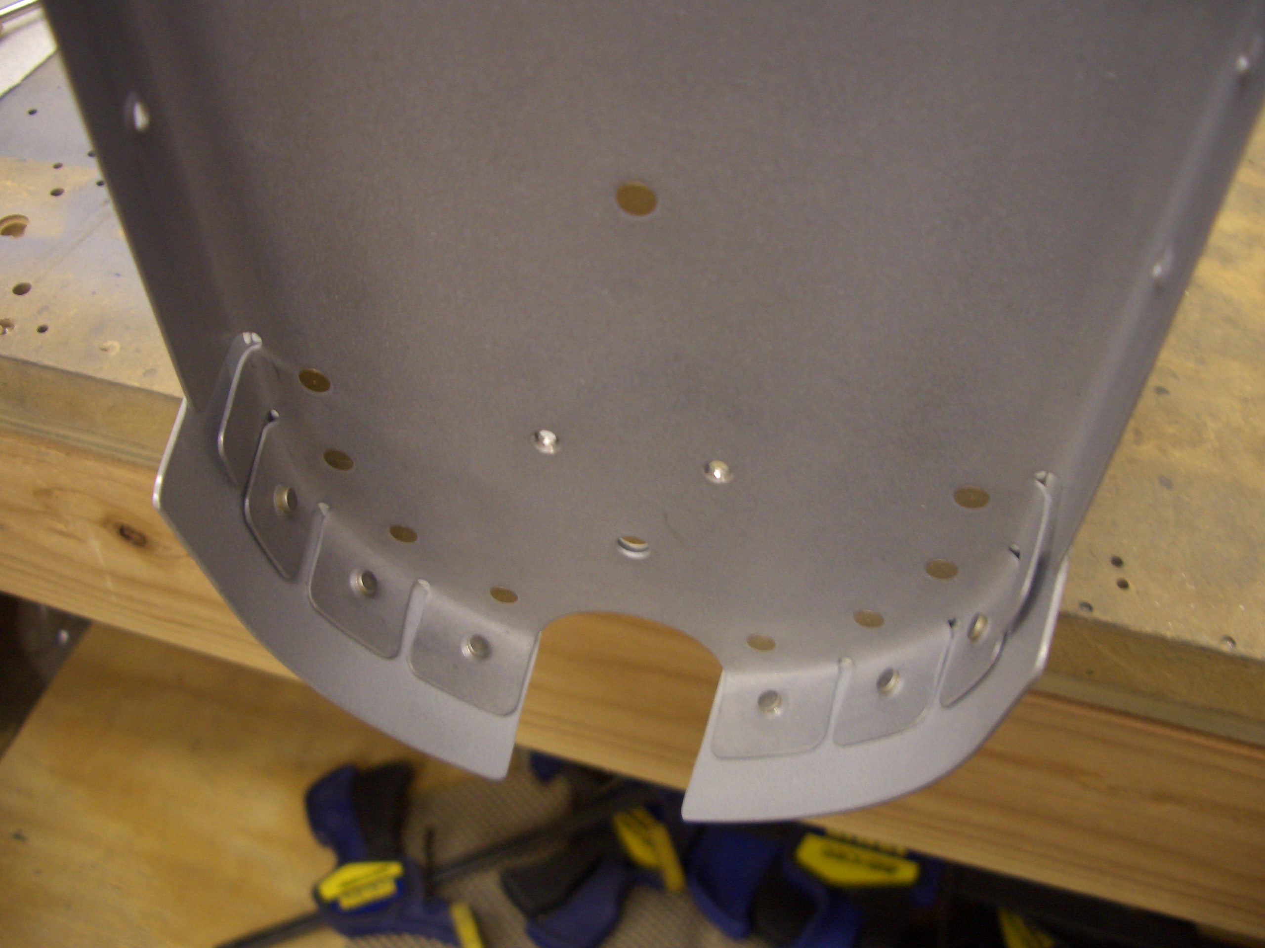
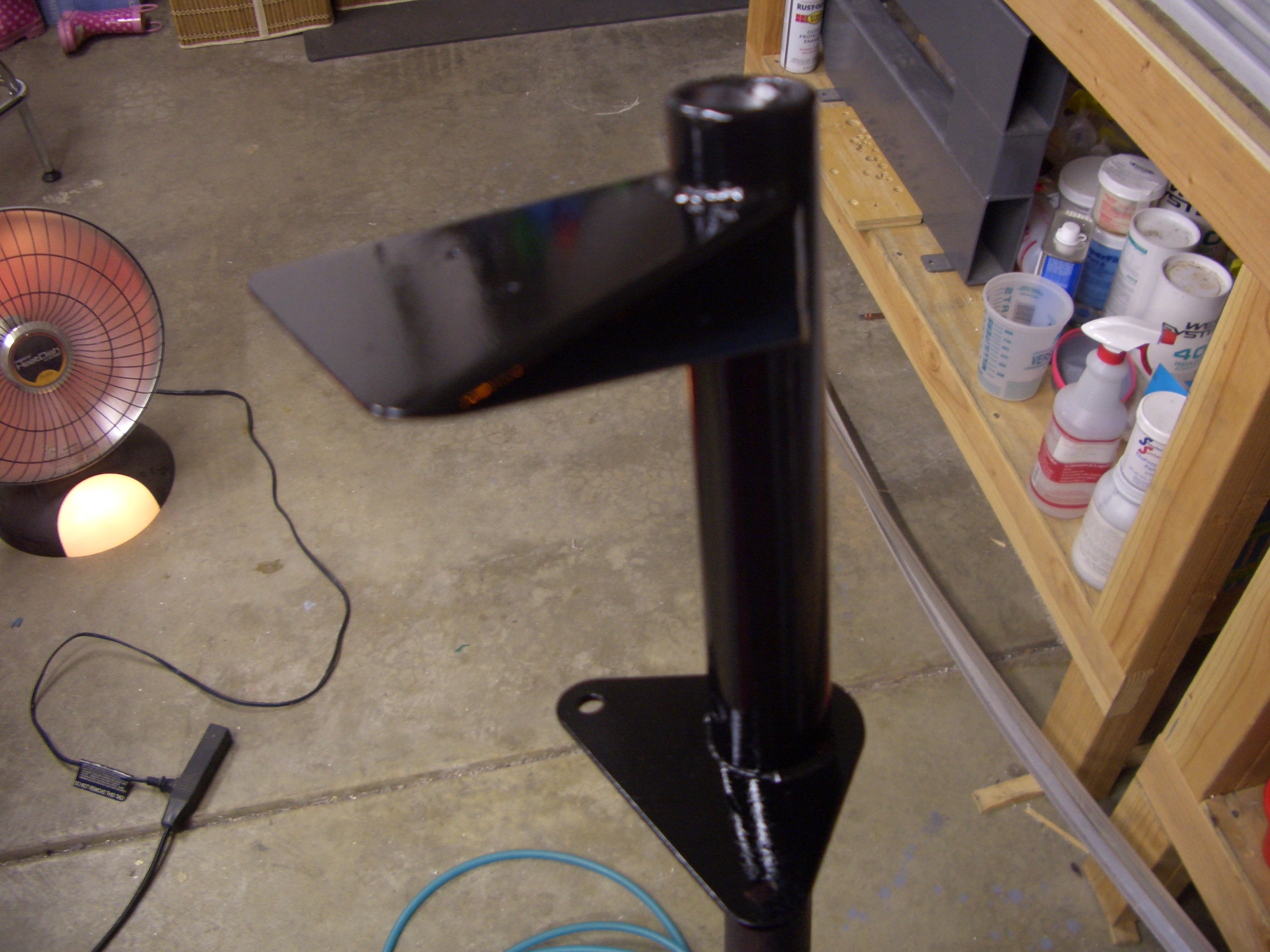
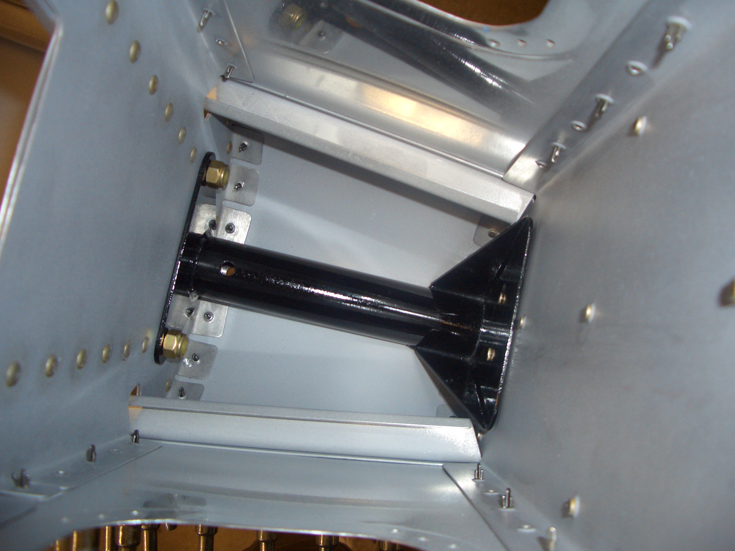
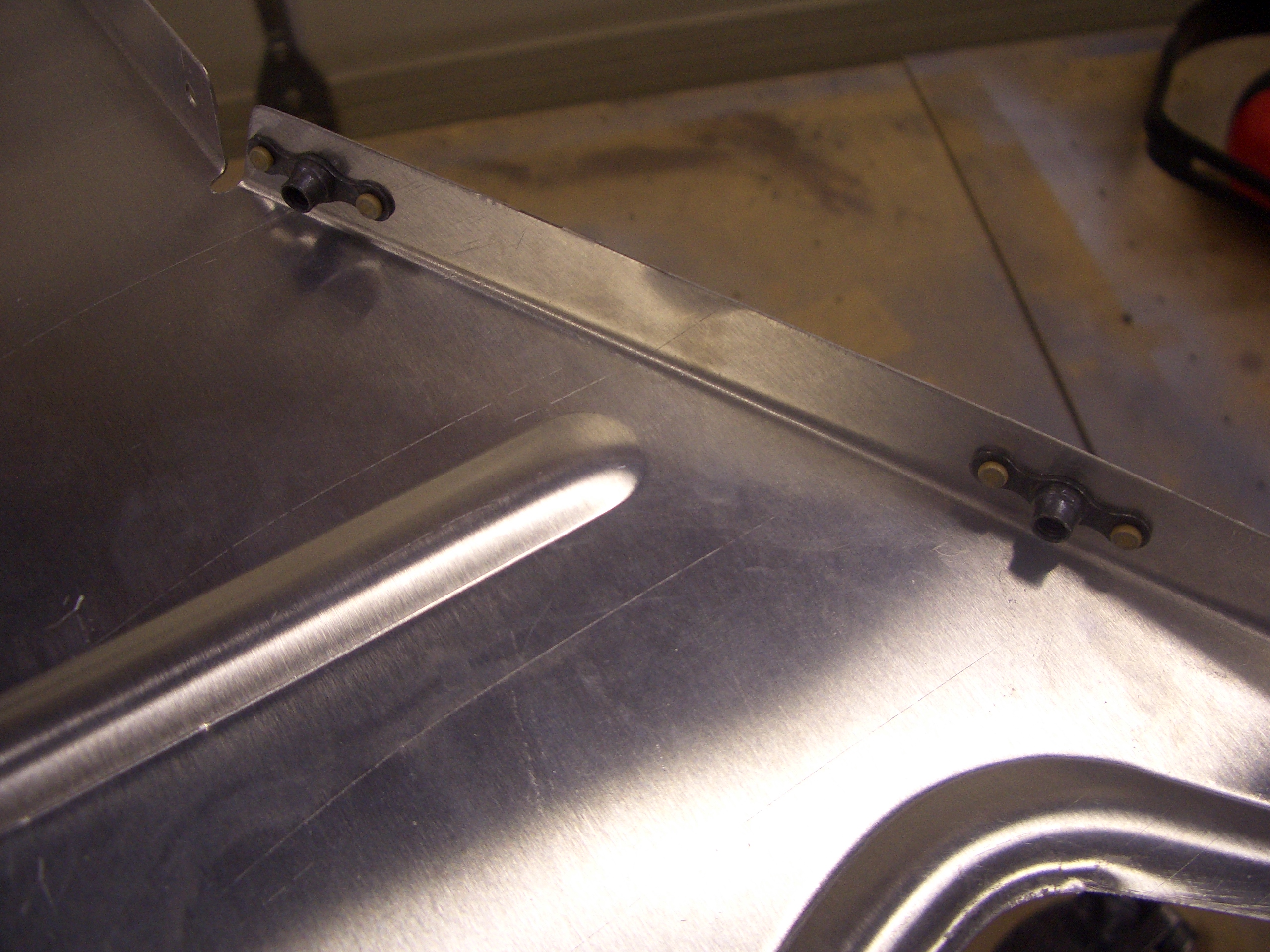
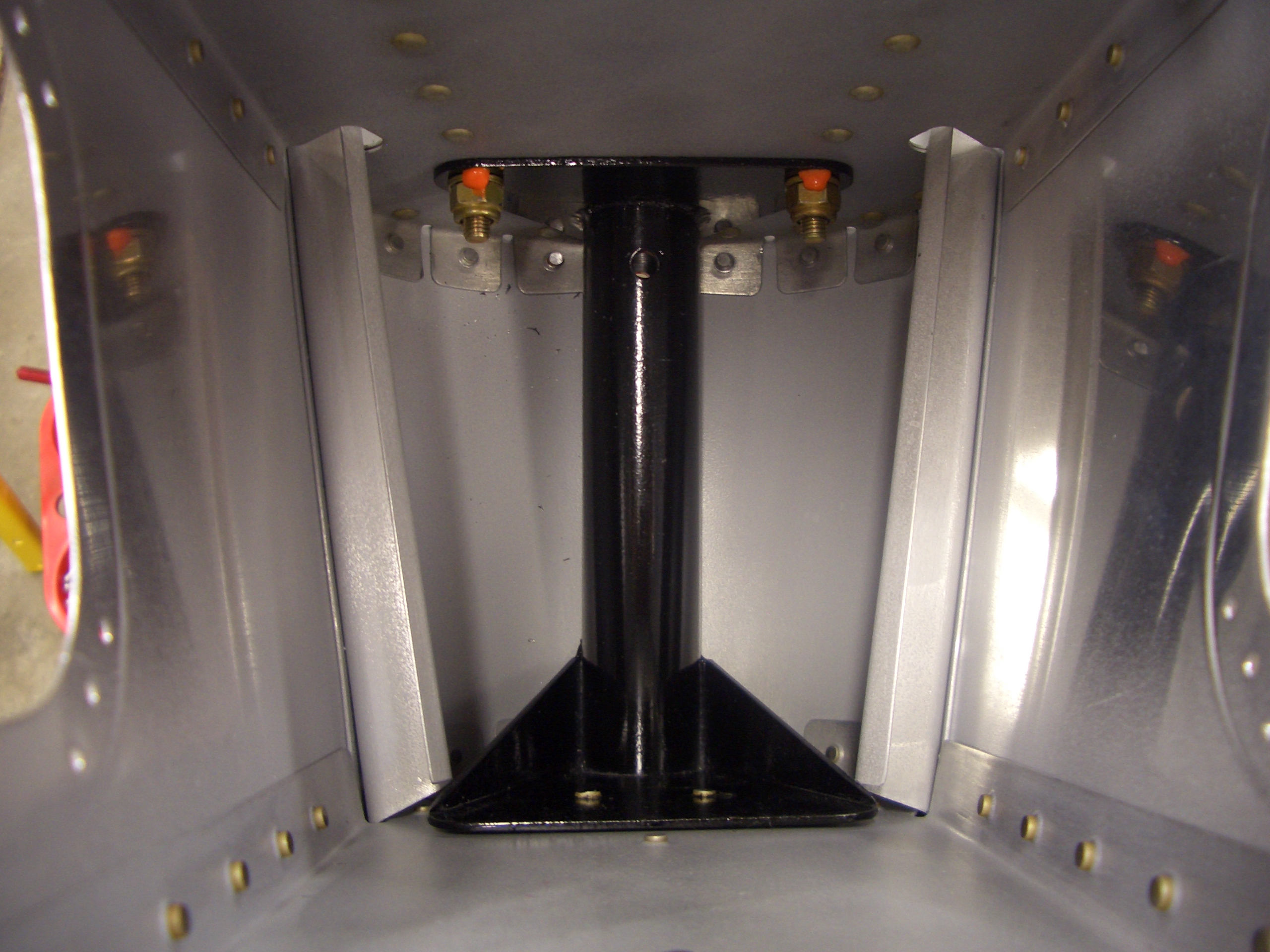
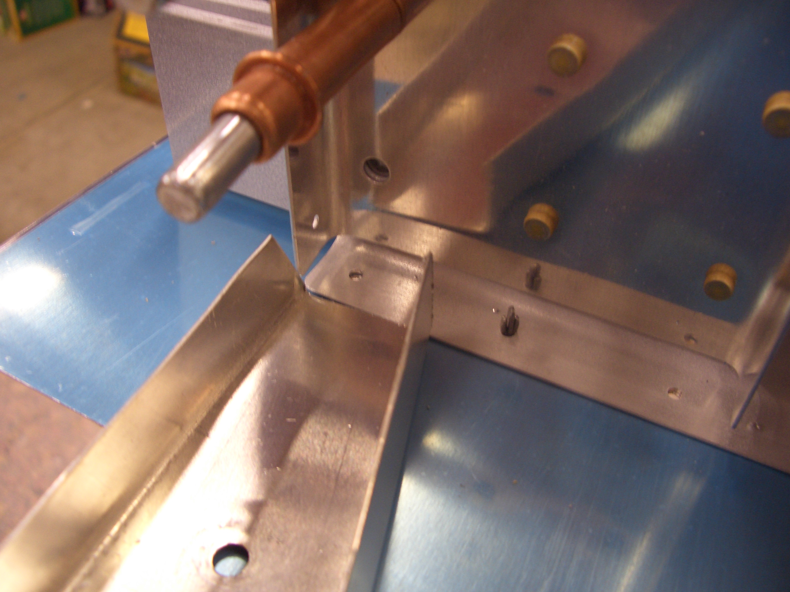
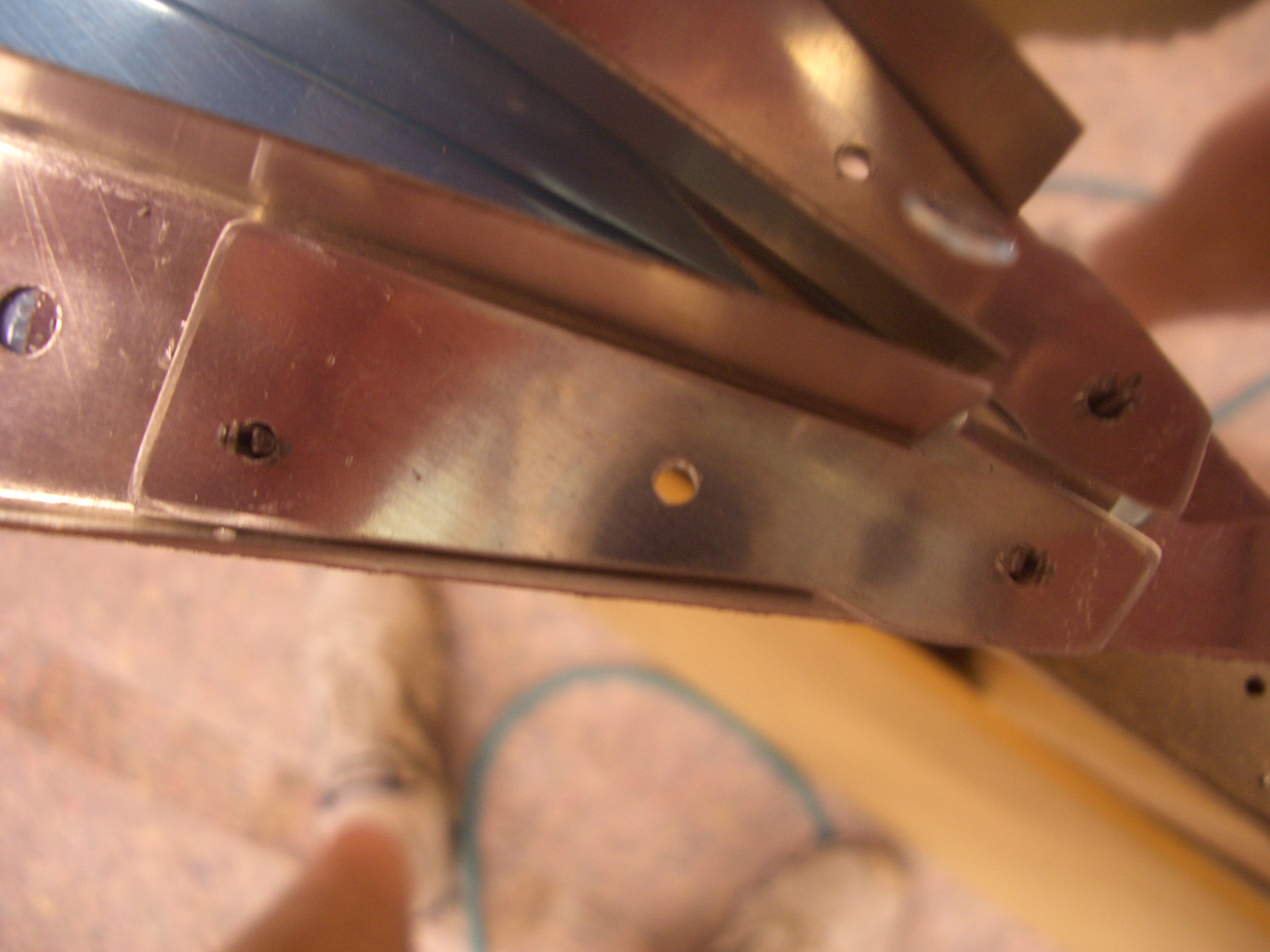
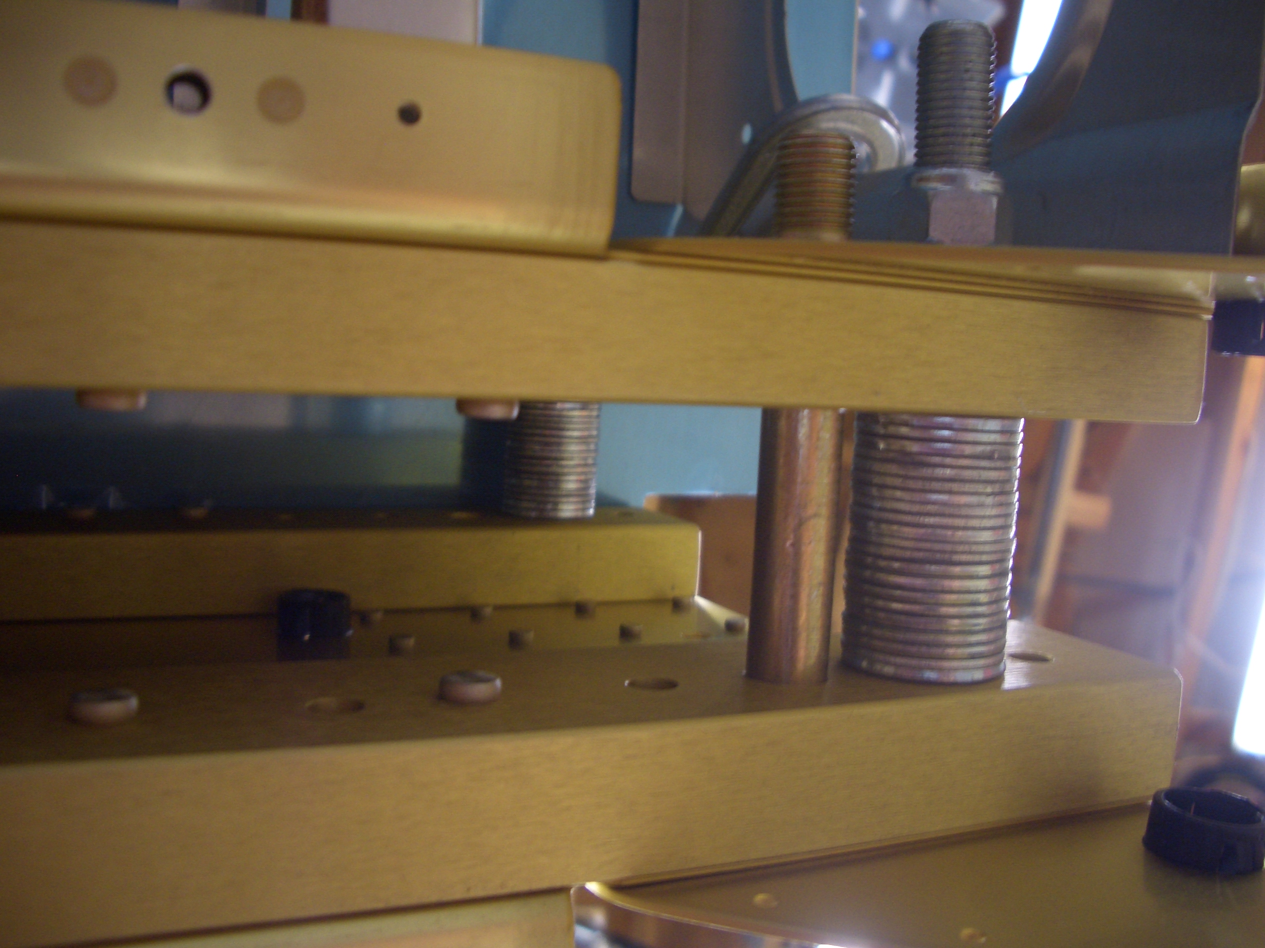
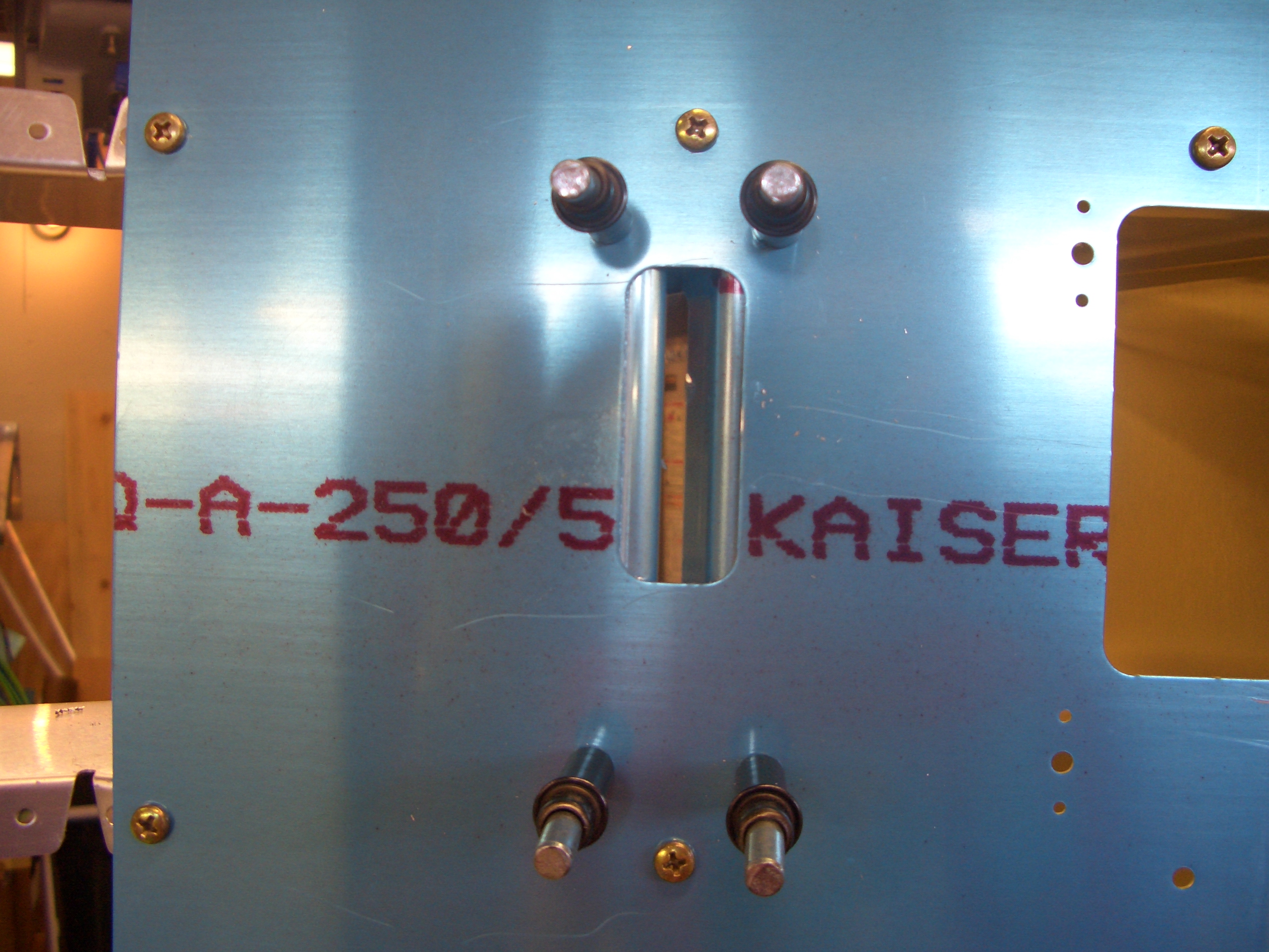
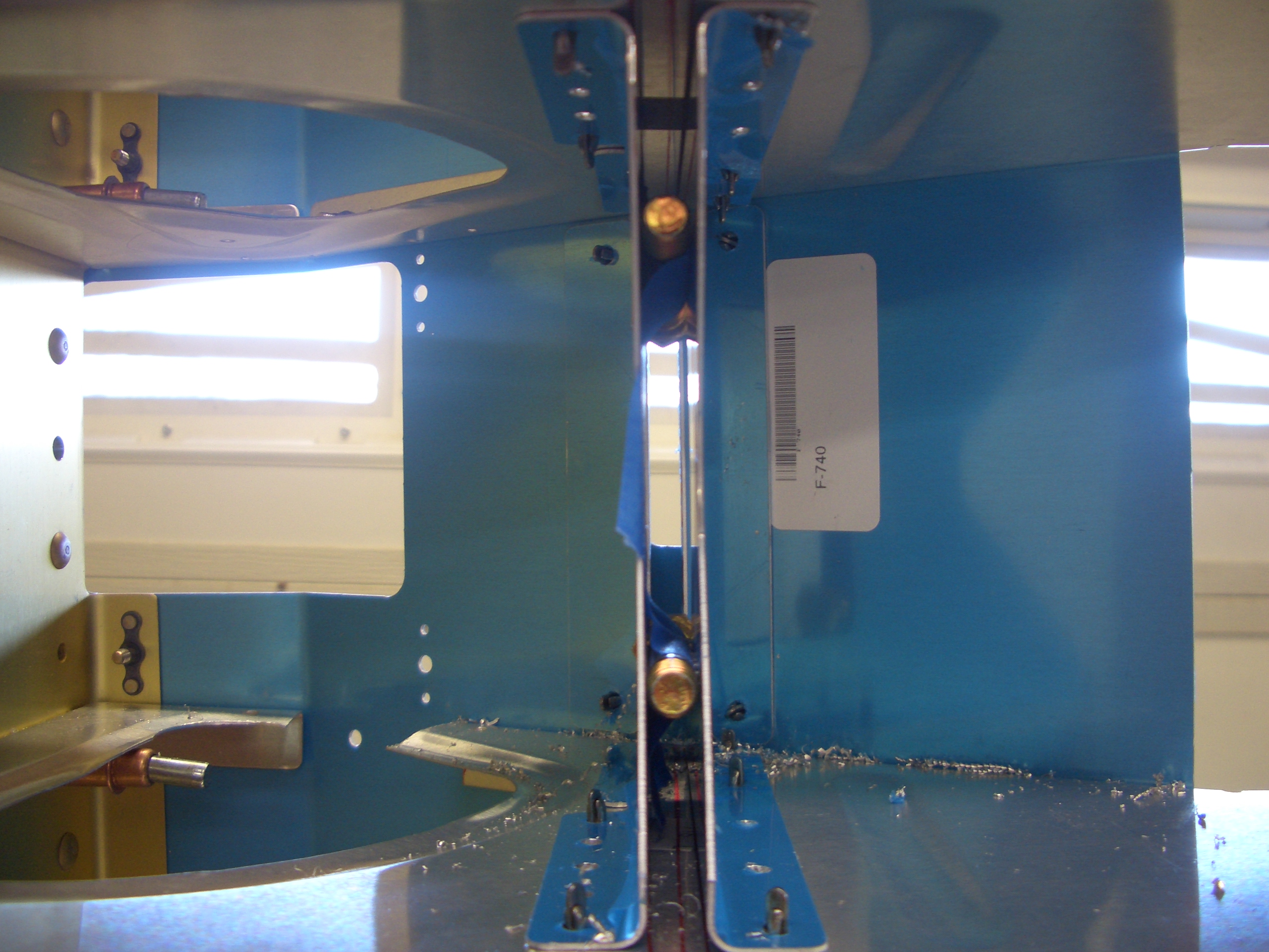
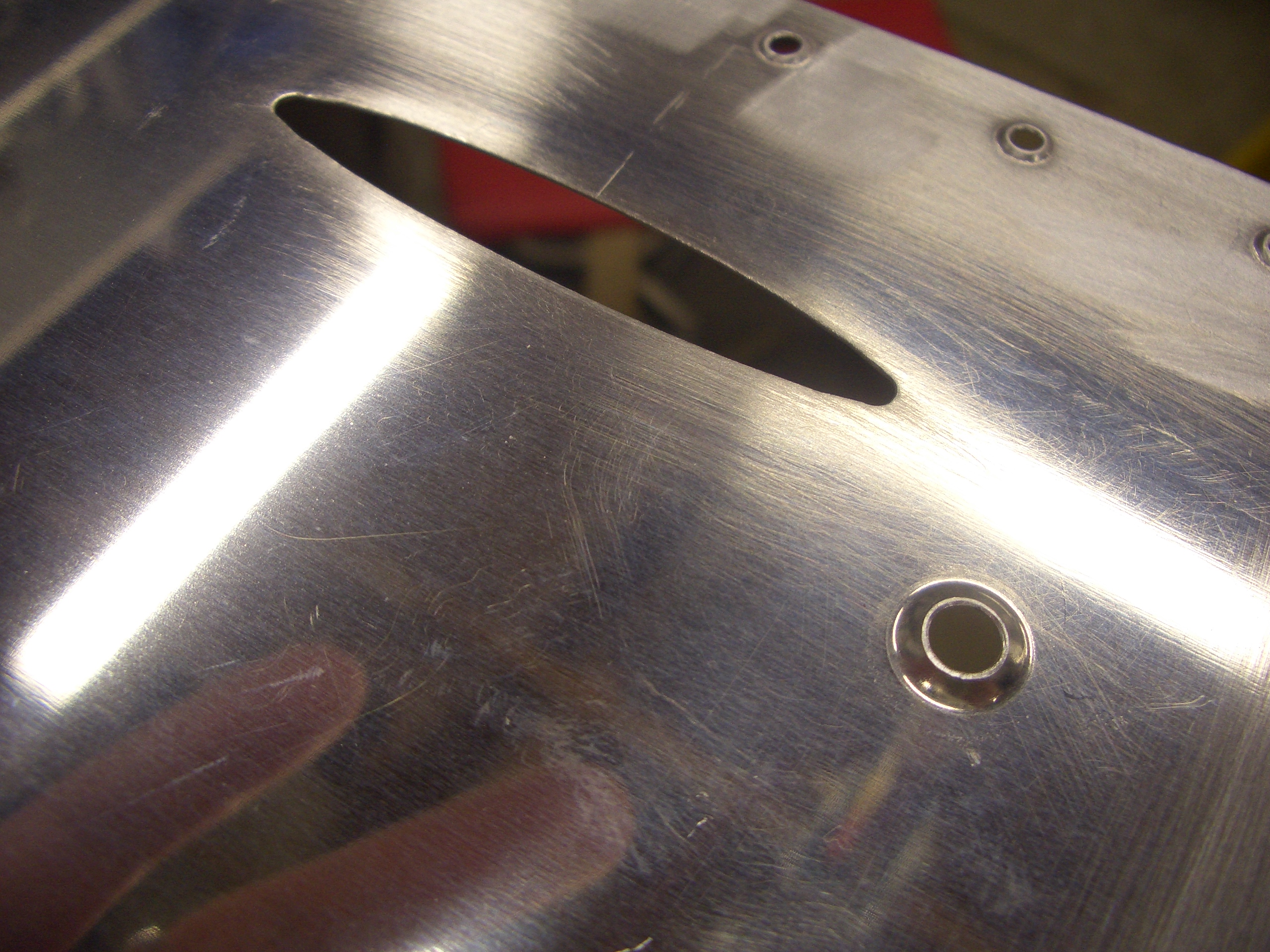
Here are the rivets on the other side of F-712 (remember that it is a double bulkhead).  The only ones that couldn’t be squeezed were the two lowest ones just next to the mouse hole.  It’s too late to fire up the rivet gun tonight, so this will have to wait.  I’m not ready to rivet the tail spring mount in place yet anyway since I want to give it a top coat of paint and the primer needs to dry for 24 hours.

I went ahead and riveted the autopilot pitch servo mounting bracket to the rib using some AN470AD4-5 rivets.  Apparently, I had forgotten to dimple the holes in the bottom of this rib, so I did that now as well.

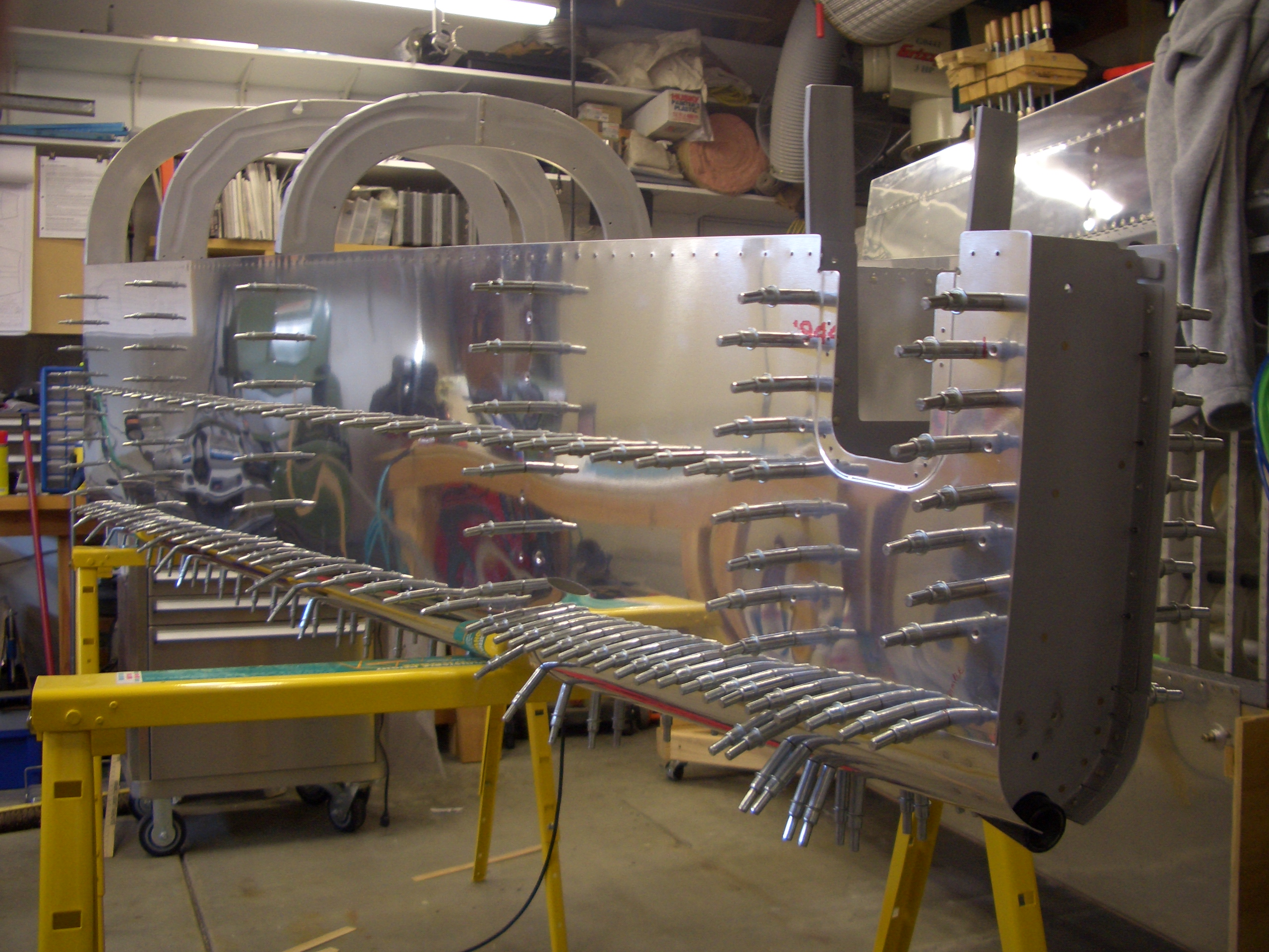
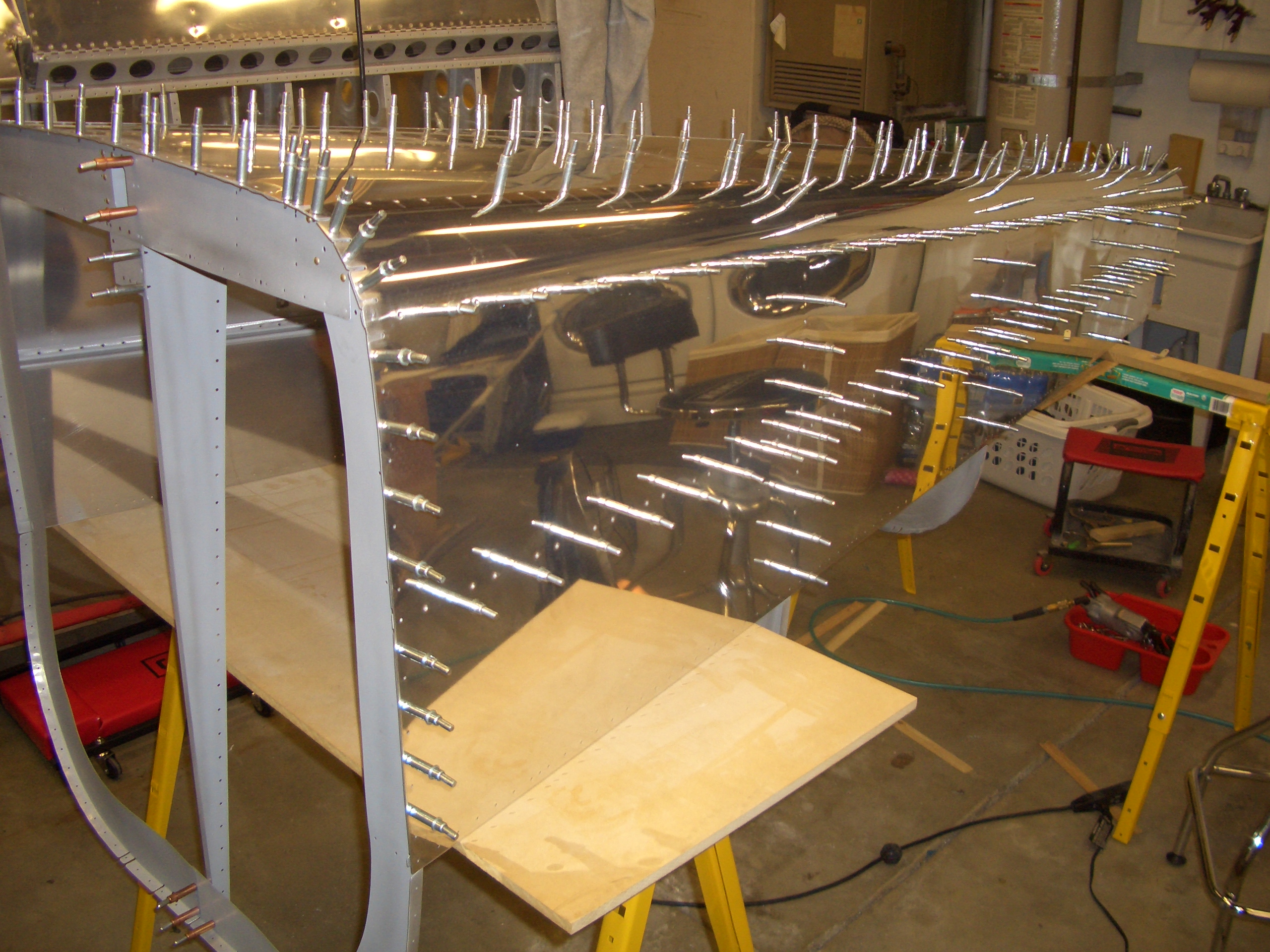
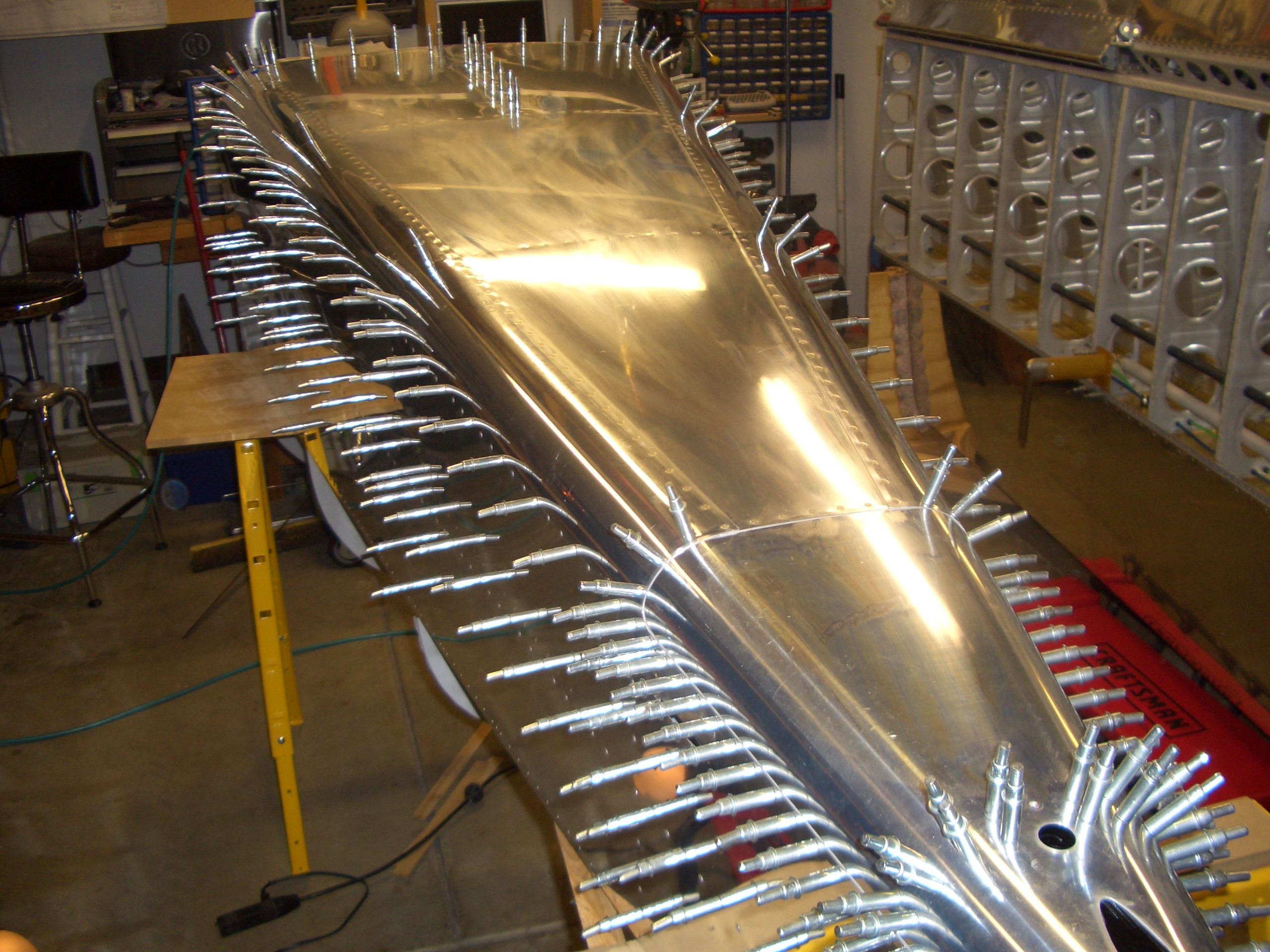
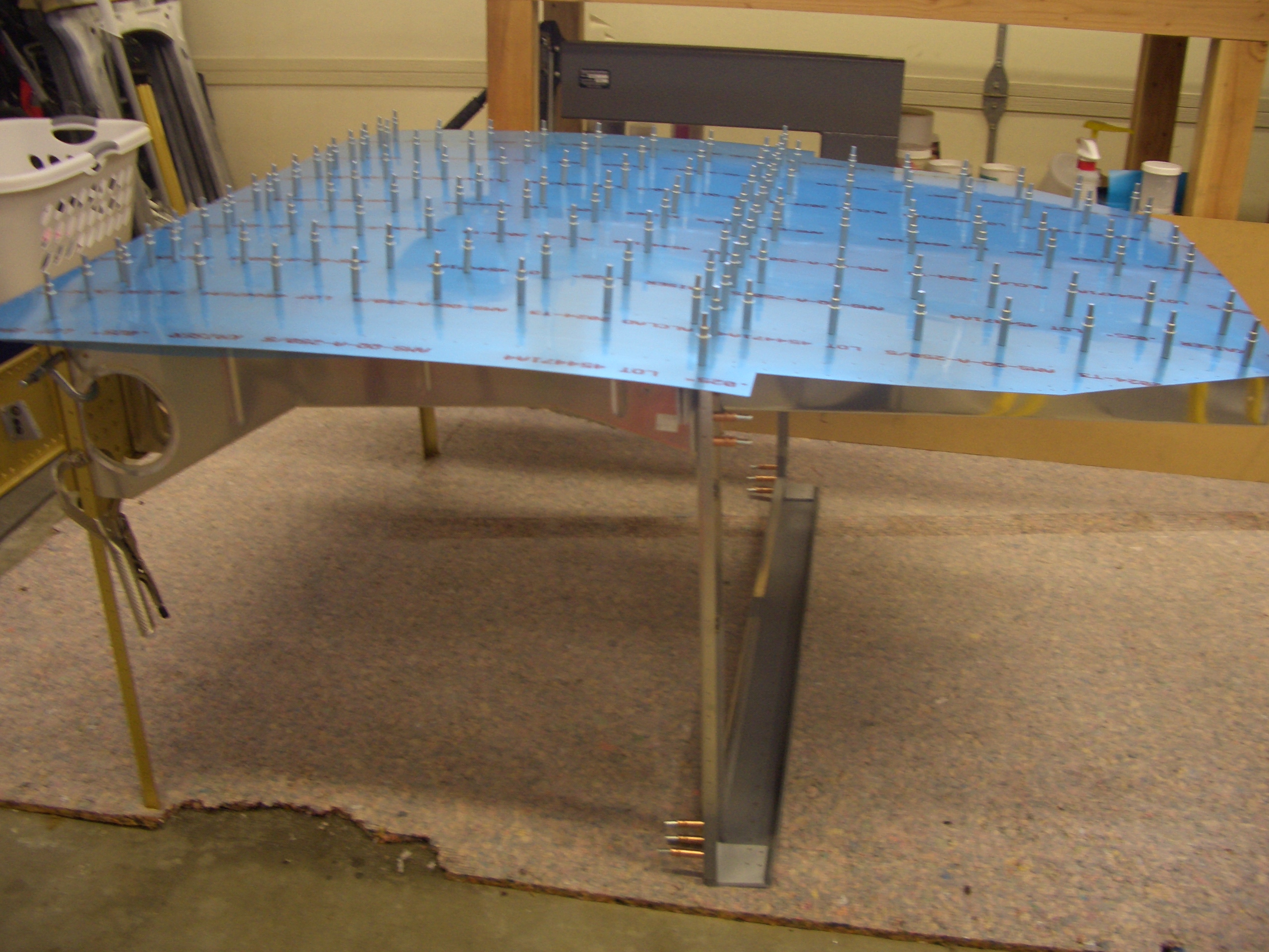
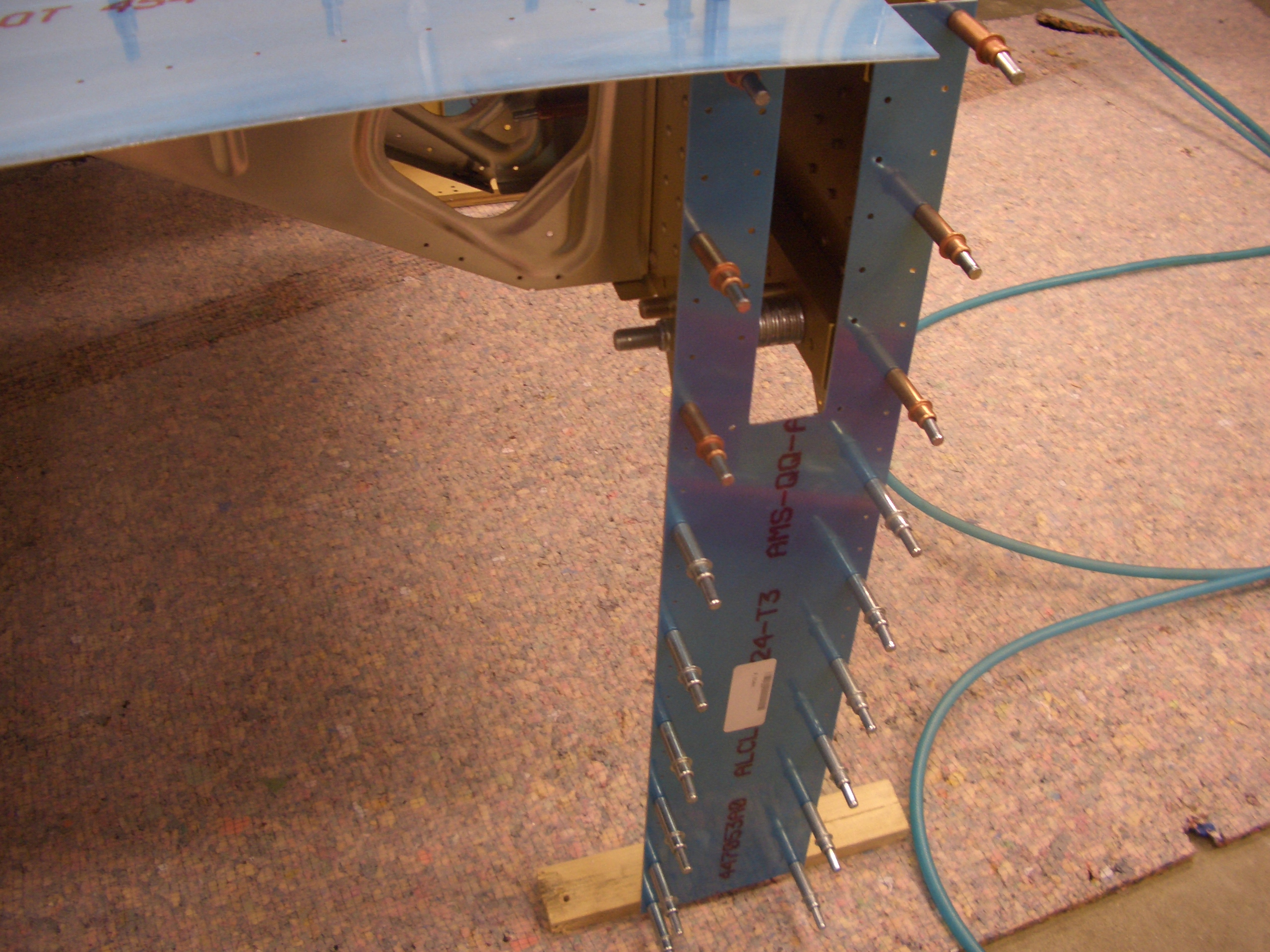
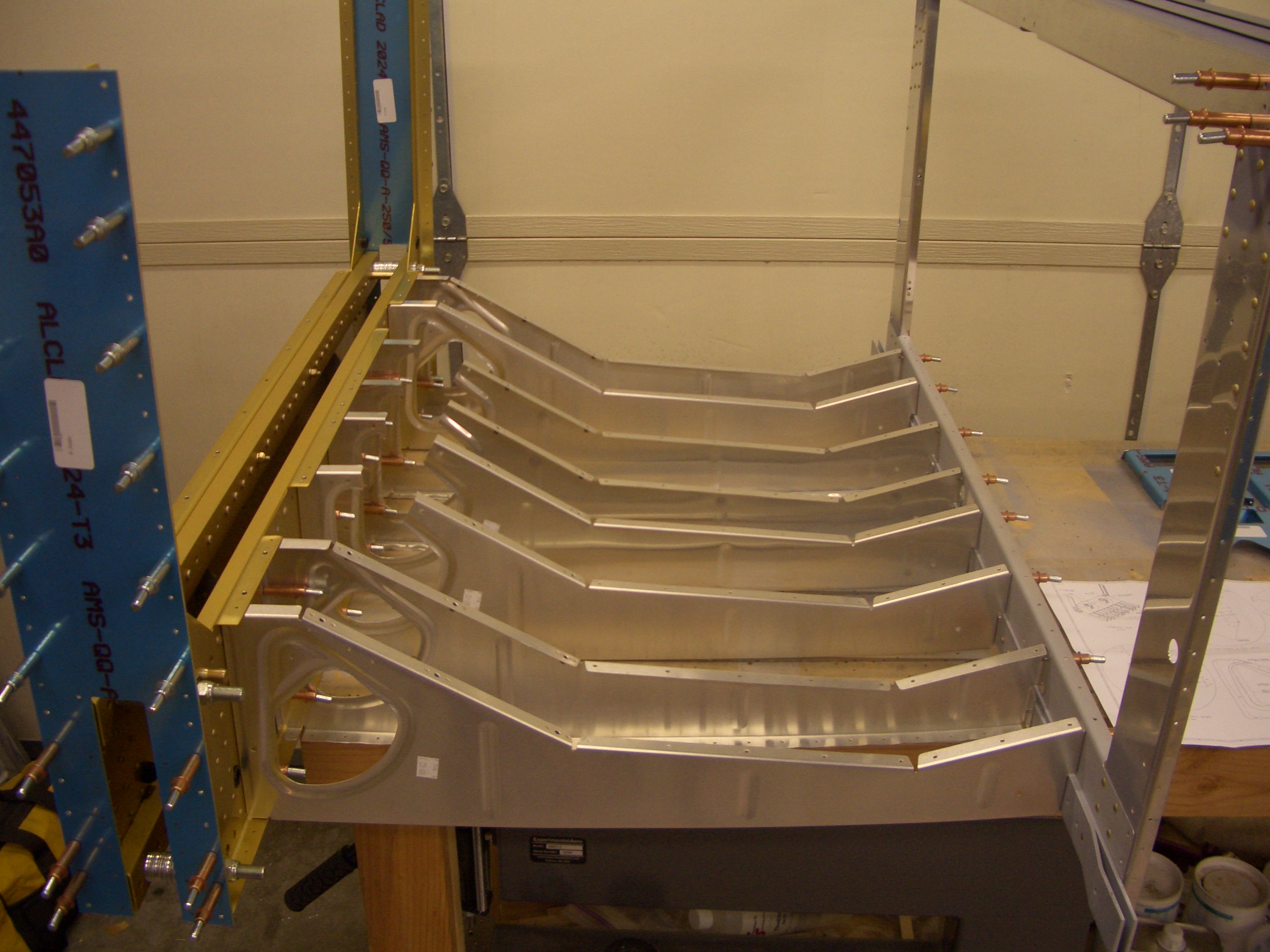
Finally, I got started clecoing the tailcone together.  It was at this point that I noticed that I forgot to prime the stringers, so I had to stop for the night.  I’ll do those tomorrow and then the tailcone can be fully clecoed together and riveting can begin.

Finished Final Wing Skin

Since it was too late to do any riveting, I decided to finish up the last wing skin.  It still needed deburring, dimpling, and edge finishing.

I also installed the platenuts around the inspection hole.  Other than riveting the bottom wing skins in place and the wingtips (which I’m putting off for the time being), there is nothing left to do on the wings.

Assembled Tailcone and Started Riveting

Now that everything in the tailcone is primed and the tailspring mount is painted, I clecoed the tailcone together.

The tailspring mount fits between F-711 and F-712.  I shot and bucked the keeper rivets the hold the mount to F-712 (you can see them on the right side of the mount here.  These just keep the mount from shifting until the bolts that tie this and the vertical stabilizer spar together are installed.

I flipped the tailcone upside down to make it more stable for riveting and shimmed it until there was no twist.

It was too late to run the rivet gun, but I squeezed all of the rivets in F-712 and all I could reach on F-711.

Worked on Longerons and Started Riveting Tailcone

I finished the gentle curve in the left longeron and clamped some 0.032″ scrap to the side to simulate the side skin.

I then laid the left side rail in place and clamped it flush with the edge of the scrap (plus a little to account for material removal when edge finishing the side rail) and drilled it to the longeron.

Next, I padded the jaws of the vise with some duct tape and clamped the longeron in place for the sharp downward bend 28 1/4″ after of the leading edge.  I also clamped some scrap steel down to the top of the longeron to keep it from lifting as I perform the bend.

Here is the longeron after putting in the 5.6º downward bend.

The longeron also needs a 17º inward twist from this point forward.  I used a large crescent wrench to give this a healthy twist.  You have to apply significantly more twist than you need to account for springback.

In the end, I got 17.1º.  Clamping the longerons to the upper engine mounts will lock in the final angle.

Here you can see that the downward bend in the longeron lines up precisely with the cut in the side skin.

My wife Jenn graciously agreed to help me get started riveting the tailcone.  Here she is manning the rivet gun.

While I was sitting on a stool under the tailcone manning the bucking bar.

We got all of the rivets holding the bottom skin to F-707, F-708, and F-710 as well as the bottom skin to side skin joints.  I still have to do the side skins to bulkheads and stringers as well as the rest of the rivets in F-711 and F-712 (the last two bulkheads).

Jenn really picked riveting up quick.  Within just a few rivets, she was shooting them perfectly almost every time.  I only had to drill out one rivet, and that was because I was holding the bucking bar slightly crooked.  Like other builders, I had to upsize a few of the rivets by 1/2 size because the size specified on the plans was too short.

Before heading to bed, I finished up the gentle curve in the right longeron and match drilled it to the side rail.  I’ll take care of the downward bend in the longeron tomorrow, then it’s on to the center section.

Started Center Section

I started the center section tonight.  This is the section containing the seats and the baggage area.  First up is to fabricate the spacers that will keep the two halves of F-704 the proper distance apart so that the wing spars can slide in easily.  The plans say to make these 1.438″ thick, but my spars were more like 1.441″, so that is the dimension I used.  My method was to superglue a number of 7/16″ washers together until I had almost enough thickness and then use shims of aluminum tape to bring the spacers to within 0.001″ or so of the correct dimension (erring slightly over rather than slightly under).

Next up was to fabricate some spacers from 1/8″ bar stock.  These will fit between the center seat ribs and the rear spar.

The plans have you modify the center two seat ribs with a small removable section so that the control center section can be removed.  Many builders modify the center four ribs instead to make this task easier.  The removable sections need clips that span the gap to retain the strength of the rib.  These are pre-fabricated out of 0.063″ sheet, but the kit only provides two.  The only extra 0.063″ sheet stock I had handy was the extra fuel tank access plates that are used when you’re not using flop tubes, so I traced the clips onto the plate and cut them out on the band saw.

After match drilling them to the existing clips, I clecoed all of them together and sanded them until the profiles matched.

Here are the four clips, ready to be installed.

To modify the ribs, the first step is to cut a 1.5″ hole around the tooling hole already provided.  I used my new Craftsman fly cutter and knocked these out in just a few minutes (the old Harbor Freight fly cutter was junk and this would have taken forever).

Here’s the result.  The area between these two holes can now be trimmed out with some snips.

Next, a small portion near the top can be snipped out.  Here it’s clecoed back in place to show how the retaining strap (on the other side) will span the gap.

Finally, a couple dozen platenuts need to be installed on the seat ribs so that the seat pan can be removed to access the controls.

I used to drill the center hole with a #19, cleco these in place, drive a screw in to make sure it was aligned with the hole and held firmly, then match drill the skin through the platenut to make sure the rivet holes were perfectly inline.  After deburring and countersinking, I would then put the screw back in to ensure the platenut was still aligned with the hole.

I think this is significant overkill though  Given the accuracy of these pre-punched kits, the holes are already exactly in the right spots, and drilling these out can’t move the hole significantly.  So tonight I tried something a little simpler.  I drilled the center holes out to #19 and the side holes out with #40, all without attaching the platenut.  After deburring and countersinking the rivet holes for NAS1097 rivets, I riveted the platenut in place without putting a screw in.  Every single one came out perfect.  This is going to make installing platenuts significantly faster from here on out.

It was late, but I wanted to cleco the center section together tonight to see what it looked like.  First up is to cleco all of the seat ribs to the aft portion of F-704.

The baggage ribs are clecoed to the aft side of F-705.

Finally, the two sections can be joined.  It was at this point I noticed that I forgot to flute the ribs (it’s nearly 1 am, so I’m obviously getting a bit tired).  This seems like a good stopping point for the night.  I’ll flute these ribs and proceed from here tomorrow.

Finished Riveting Tailcone and Fluted Center Section Ribs

My dad stopped by tonight and helped me knock out the rest of the riveting on the tailcone tonight.  It was his first time, but he picked it up really quickly and the rivets look great.

I also put the correct bolts into the tailwheel mount through F-711 and torqued and sealed them.

To save space, I stood the tailcone up on a blanket.  This freed up a significant amount of floor space that I’ll need while working on the center section.  I’ve got to get the wings out of here soon or I’ll run out of room.

I also fluted all of the seat ribs and squared the flanges.  I haven’t rejoined the seat ribs to the F-705 bulkhead yet though.

Two of the ribs need relief cuts to clear wiring holes in F-704.

The same thing goes to two of the ribs attached to F-705.

Drilled Seat and Baggage Ribs

I started tonight by match drilling the bottom skin to the seat and baggage ribs as well as the F-704 and F-705 bulkheads.  Next I got started on the F-623 side ribs.  There is a joggle in these that makes it look like it could nest inside F-705, but this is apparently a holdover from the RV-6 and must be cut off.

The side rib should sit behind F-705 like this.  They will be connected with a strap that has to be fabricated.

The aft end of the side rib must be cut off as well. I positioned a ruler where the front edge of the F-706 bulkhead will sit and marked the rib.

After cutting of the ends, I clamped the rib in place and match drilled it to the bottom skin.

The plans specify attachment straps that connect F-623 to F-705 that are 3/4″ wide.  This is too wide to hit just one row of rivets here, but not wide enough to catch both rows.  Most builders just narrow the strip to 1/2″ and catch just the outer row of rivets, but I decided to make the strip a little wider and catch both rows of rivets.

The aft attachment straps will have edge distance problems if fabricated according to plans.  Instead, I made the strap widen somewhat as it exits F-623 so that the aft rivet (on the right in the picture below) will have sufficient edge distance on all sides.

I clamped the two side ribs together to transfer the cut marks from one to the other.

I clamped the two halves of F-704 together using the spacers I made and some hardware store 7/16″ bolts.  I put two of the close tolerance bolts in place (one in each end) to ensure the bulkhead halves were perfectly aligned since the hardware store bolts allowed a little slop.

I then clecoed the side skin doublers in place and match drilled them to the F-704 side pieces.

Four of the rivets along the front edge of F-704 must be countersunk so that the F-704 flange isn’t dimpled.  This is to allow the floor stiffeners to nest against this flange.

The bottom skins is only 0.025″ thick, which is not thick enough to take a countersink for a 3/32″ rivet.  This causes the countersink to penetrate slightly into the F-704 flange.  This is ok in this particular case.

Afterward, I removed the bottom skin and baggage ribs.

I pulled out the crotch strap install kit, but I need to get up really early tomorrow, so I’m going to call it a night.

Finished Prepping Center Section

I started today by installing the crotch strap brackets.  I’m either going with Hooker or Crow harnesses, but either way, the spacing between the brackets has to be increased to 5/16″ (instead of the stock 1/8″ spacing).  Mike Bullock already determined the best way to accomplish this and documented it here, so I’m just going to copy his method (thanks Mike).  I put a center line that is aligned with middle nutplate, then measured 7/32″ forward and 3/32″ aft of this line and put additional marks.

The front side of the bracket is positioned with the web flush with the forward line and drilled to the adjacent ribs.

Instead of cutting a 5/16″ spacer, I just used a couple of AN5 bolts which are 5/16″ in diameter.  I taped them in place and clamped the aft side of the bracket against the bolts and against the seat pan, then drilled the bracket to the adjacent ribs.

The prepunched holes in the seat pan need to be drilled to #19 for #8 screws.

Here is the backside, showing good edge distance on the #19 holes.

After repeating the process for the right bracket, I finished up a few remaining tasks such as drilling the seat ribs to the aft side of F-704, match drilling all ribs to bulkheads, and drilling out the forward tooling holes to 5/8″ for wiring runs.  I then disassembled the center section and started prepping the individual components.

First up is to debur and dimple the holes in the bottom flanges of F-704.  Remember that the holes we countersunk in the bottom skin have to be skipped when dimpling so that the floor stiffeners can lay flush against this flange.

Neither the instructions nor the plans make any mention of these holes in the top flange of the aft side of F-704, but the seat pan that sits above this is removable, so this must just attach the top of the seat ribs to the F-704 flange.  Since the seat pan needs to sit flush against this flange, I countersunk this for an AN426AD3 rivet.

Finally, I started deburring all of the components.  I made it through the F-704 and F-705 bulkheads and six of the eight seat ribs before running out of steam.  I should be able to finish deburring the rest of the center section components tomorrow.