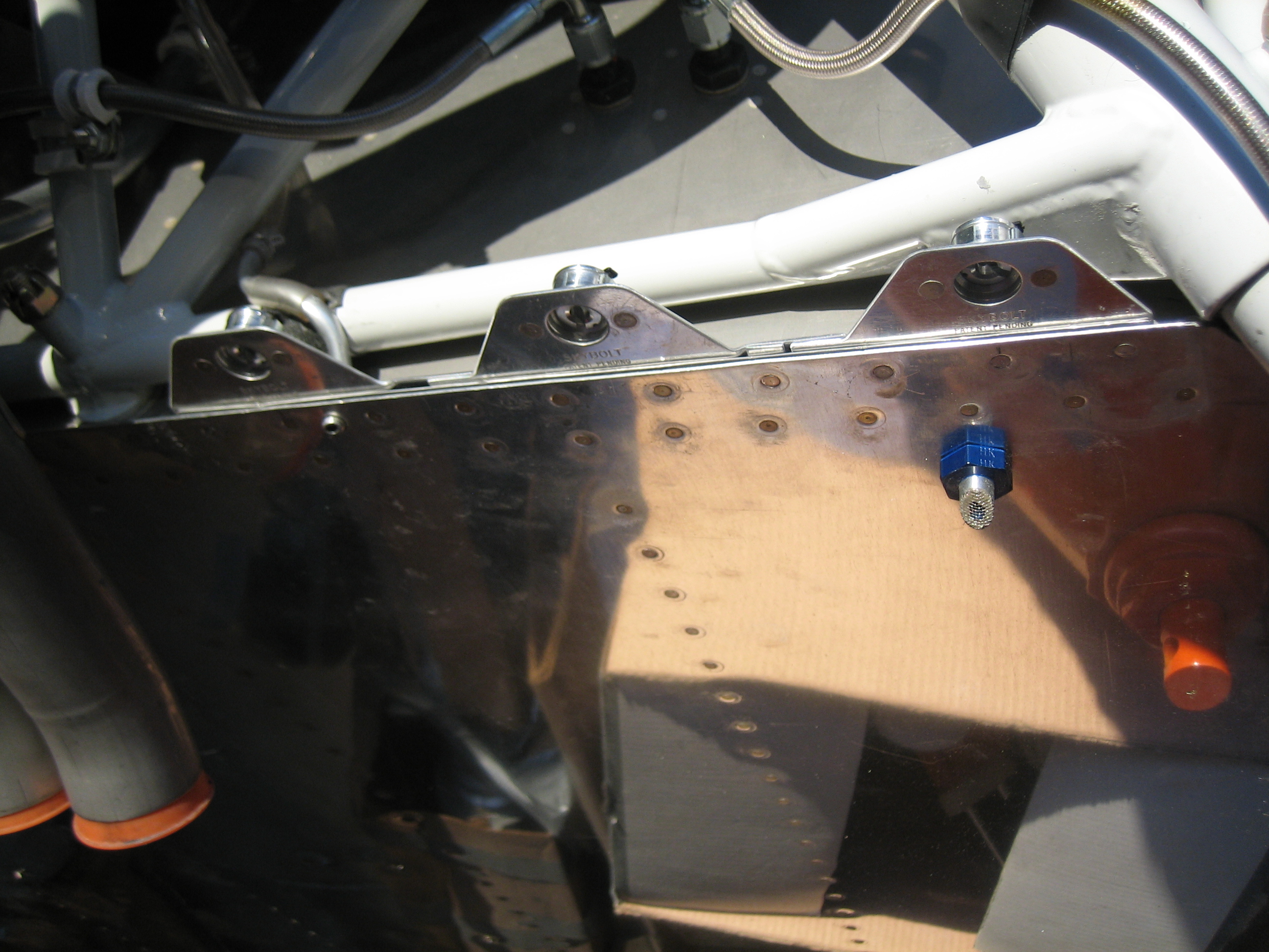
I riveted on the flanges and then riveted the receptacles in place. You can see a small black tab at the top of each one, that’s the anti-lock pin that allows the receptacle’s adjustment mechanism to turn freely.
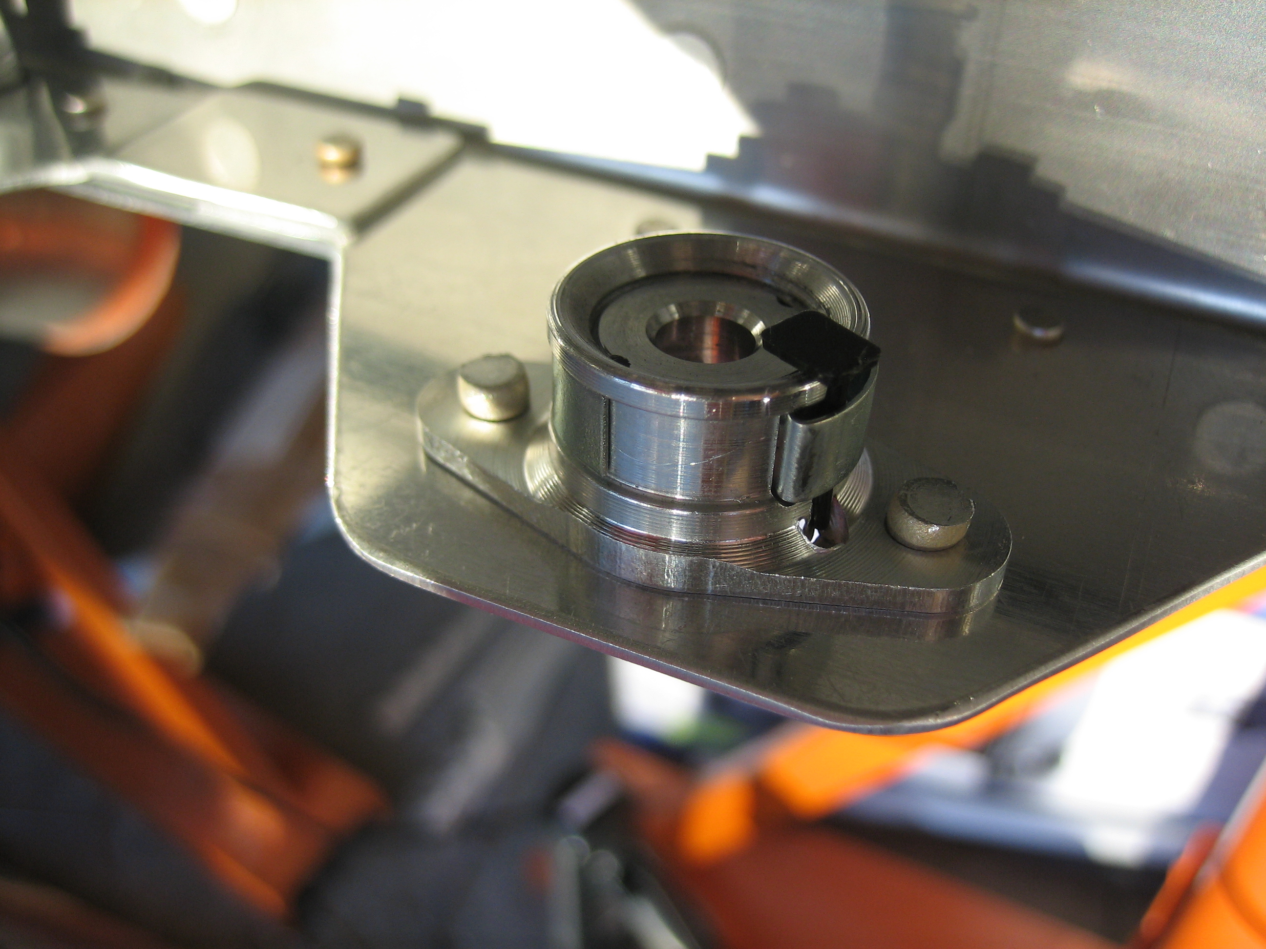
Here’s a closer look at one of the receptacles and the anti-lock pin. You can see that the pin is holding the spring out which allows the inside portion to turn. It’s threaded into the outer housing so that you can adjust the receptacle for different panel thicknesses.
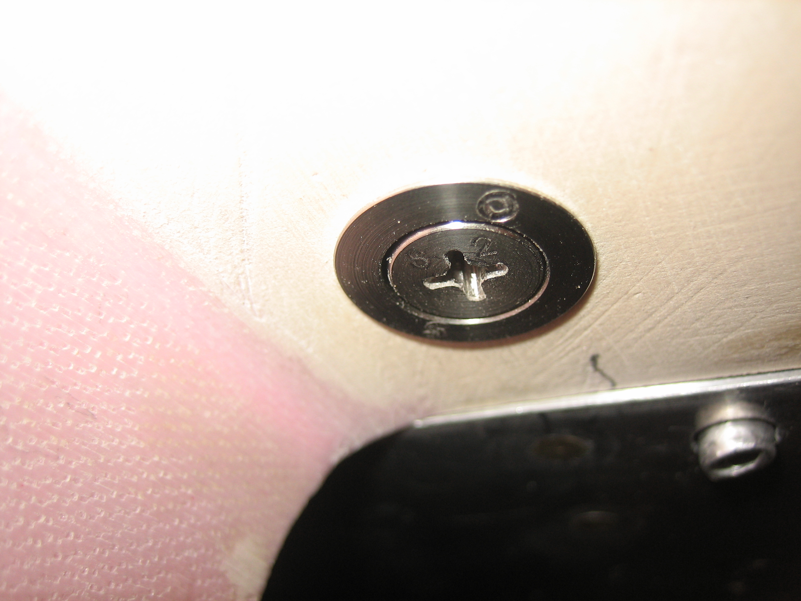
With the grommets and studs installed in the cowl (and held in place with thin o-rings for now), the studs can be locked into the receptacles and then tightened until they’re flush with the grommets. This compresses the spring on the stud which provides sufficient clamping force to prevent the stud from unlocking from the receptacle. After I adjusted the studs so that they were flush with the grommets, I removed the cowl and then removed the locking pins so that the receptacles can’t move.
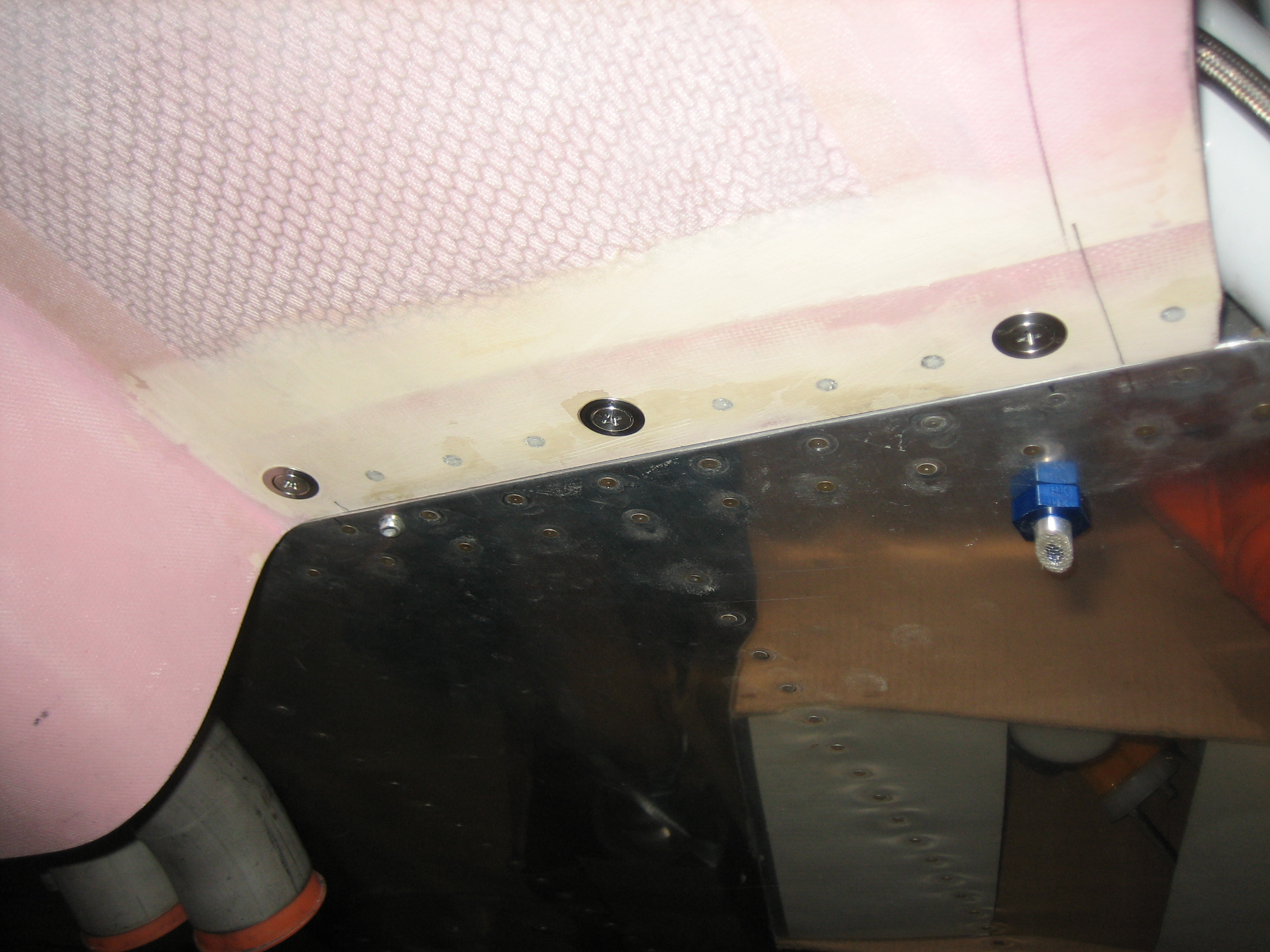
You can see that this results in a nice flush fit for the stud. You can also see in this picture that the cowl is now a little bit recessed below the plane of the lower fuselage skin. I still need to add some filler to this area to smooth out all of the filled rivet holes. If that doesn’t bring these into perfect alignment, I can always add a shim to the flange to space the cowl down a bit. Overall, I’m really happy with how these turned out and I think I will like this approach far better than the hinge pins I originally went with.