Laid Up Additional Glass on Plenum

I made one last little tweak to the plenum to get the inner edge of the right inlet to lay flush against the baffles.  I used some 5 minute epoxy so that it would be cured enough to do the rest of the layups later in the day.

While I was waiting for that to cure, I installed the blast tube for the magneto.  It’s anchored to the breather tube and is sitting about 1/4″ above the mag.

In preparation for doing the additional layups, I hot-glued the plenum down to the mounting angles.

I then laid up three layers of 9 oz glass using the high-temp epoxy.  I’ll see how stiff this is tomorrow and will add a layer of carbon fiber if it’s not stiff enough.

Prepped Plenum for Mounting

I popped the plenum off the mounting angles (releasing the hot glue I had used to attach it).  I then trimmed most of the excess glass off of the edges.

I then laid out and drilled pilot holes for all of the attach screws that will attach the plenum.  I put holes at all of the corners and will use nutplates that span the joints.

Drilled Plenum and Started Riveting Mounting Angles

I drilled the plenum to the mounting angles through the holes I drilled in them yesterday.  I shined a light through the plenum so that I could see the holes.  They’re only drilled out to #40 now, but I’ll open them up for #8 screws once the mounting angles are riveted and I know everything is in it’s final location.  The spacing varies somewhat around the perimeter based on the length of the various mounting angles, but they’re predominantly between 1 5/8″ and 1 7/8″.  They’re tighter at the front outside corners where the plenum turns sharply downward.

I pulled the plenum and baffles off so that I could rivet the mounting angles to the baffles.  The engine hasn’t been this naked in a very long time.

I started cleaning up and riveting the mounting angles to the baffles.  The mounting angles need quite a bit of time with the deburring disks on the die grinder due to the fairly deep marks put in them by the shrinker/stretch dies.  Notice that the aft rivet (on the far right in this picture is flush on the outside because the #4 cylinder baffle tucks in here.

Routed Wing Wiring Outside of Fuselage, Replaced Oil Drain

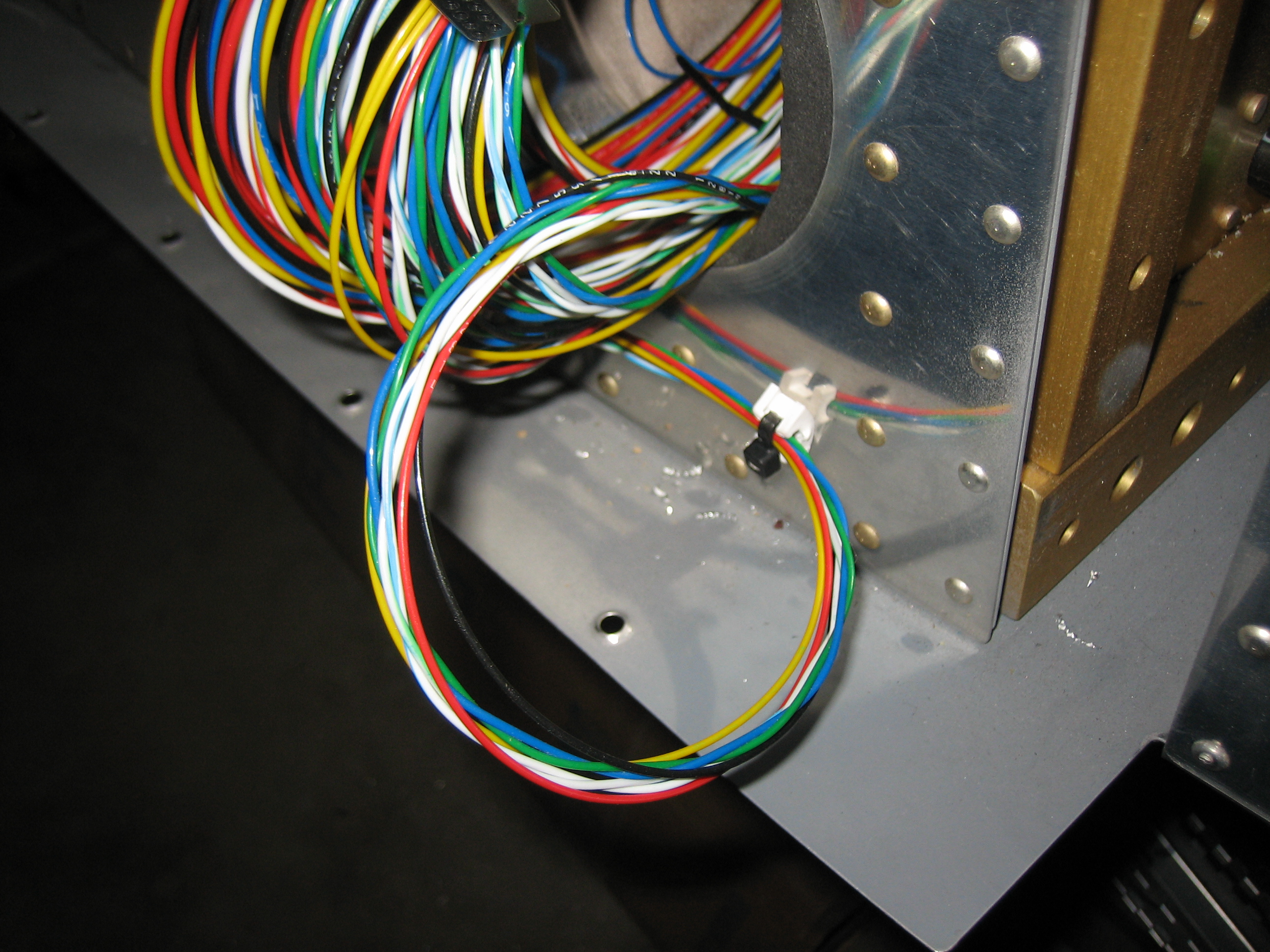
I drilled holes in the sides of the fuselage for the wing wire runs and fished them through along with a grommet.  To keep the wires out of the way, I coiled them up and tucked them back into the aileron push-rod hole.

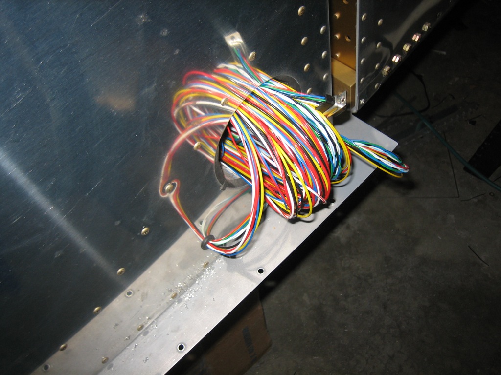
The wing tip wiring will go straight into the wing wiring conduit from the hole I drilled, but the roll servo cable turns forward from there and then needs to go up to a hole near the top of the wing to route down to the servo.  I pop-riveted a wire clamp to the side of the fuselage to anchor the cable and keep it away from the aileron pushrod.

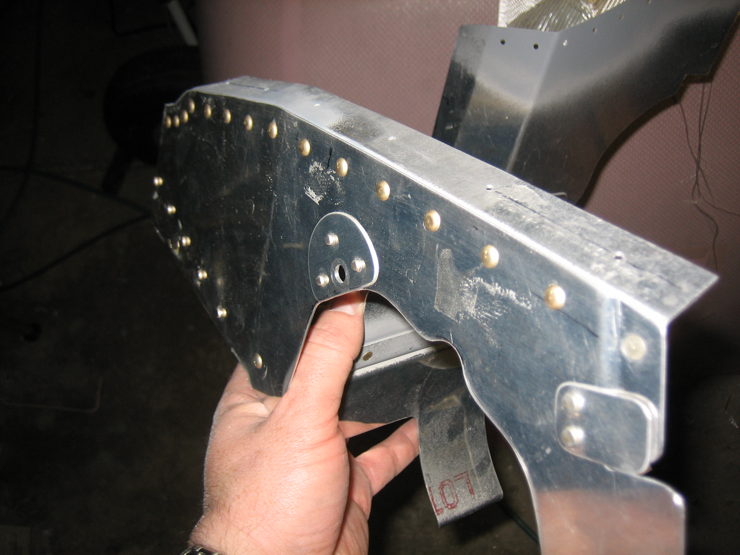
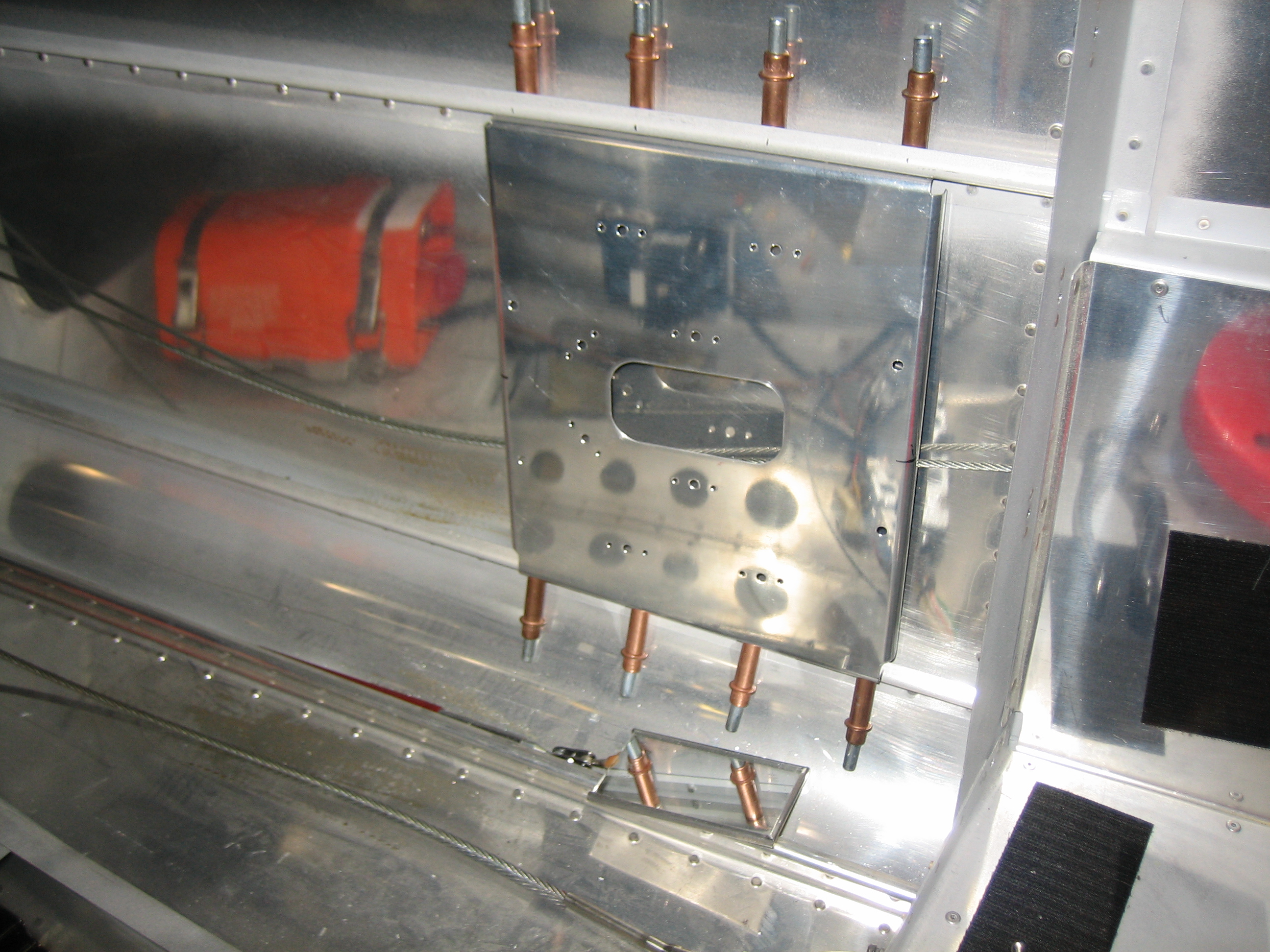
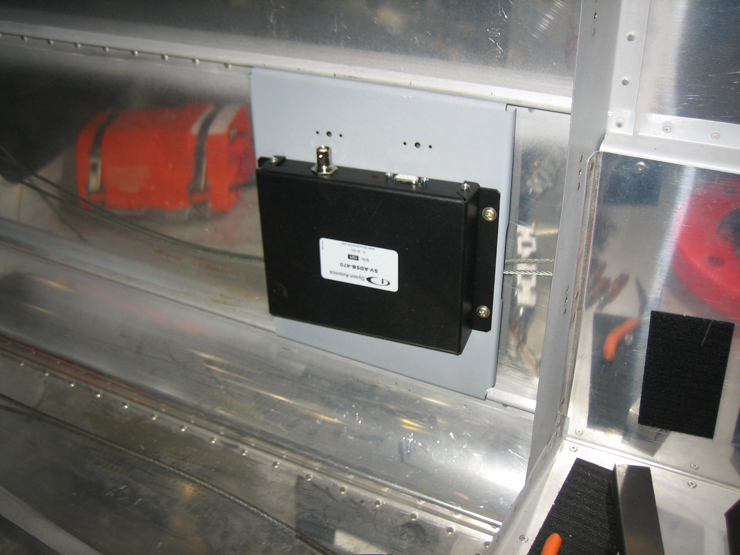
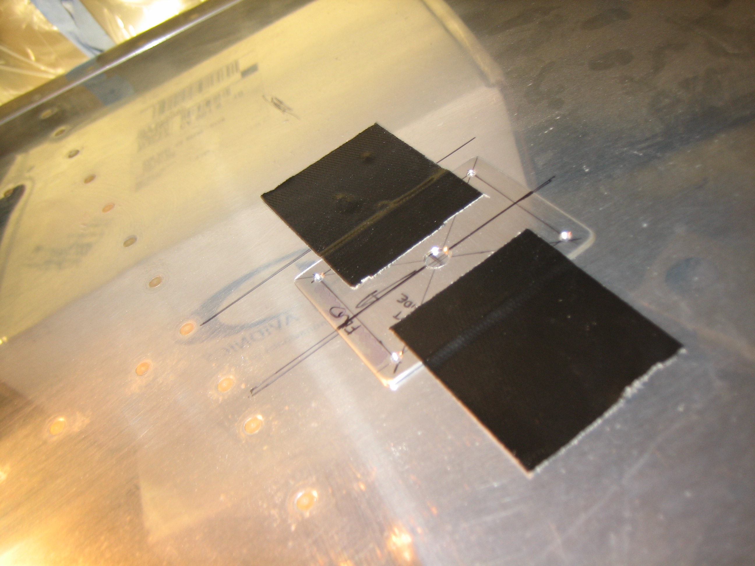
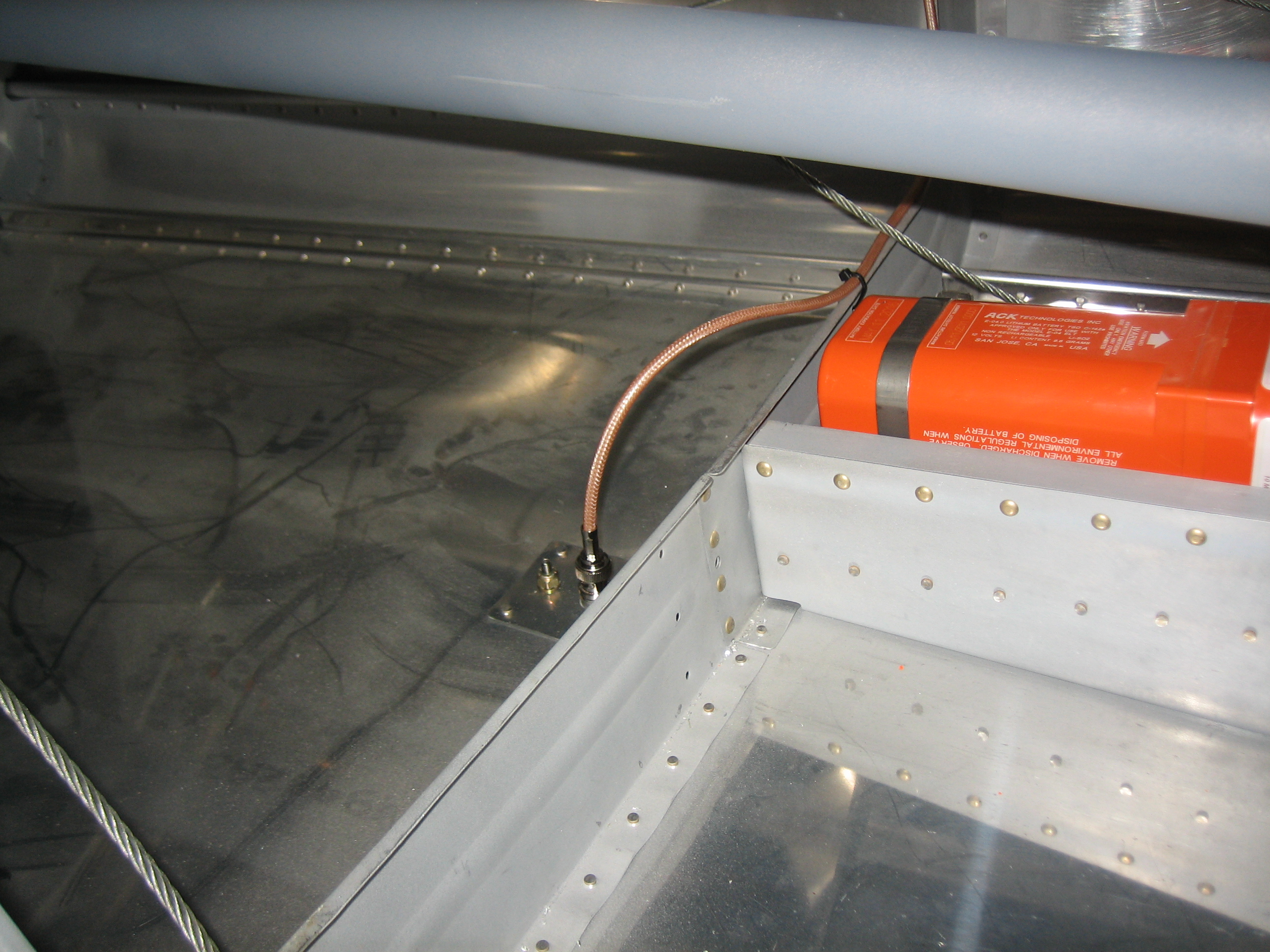
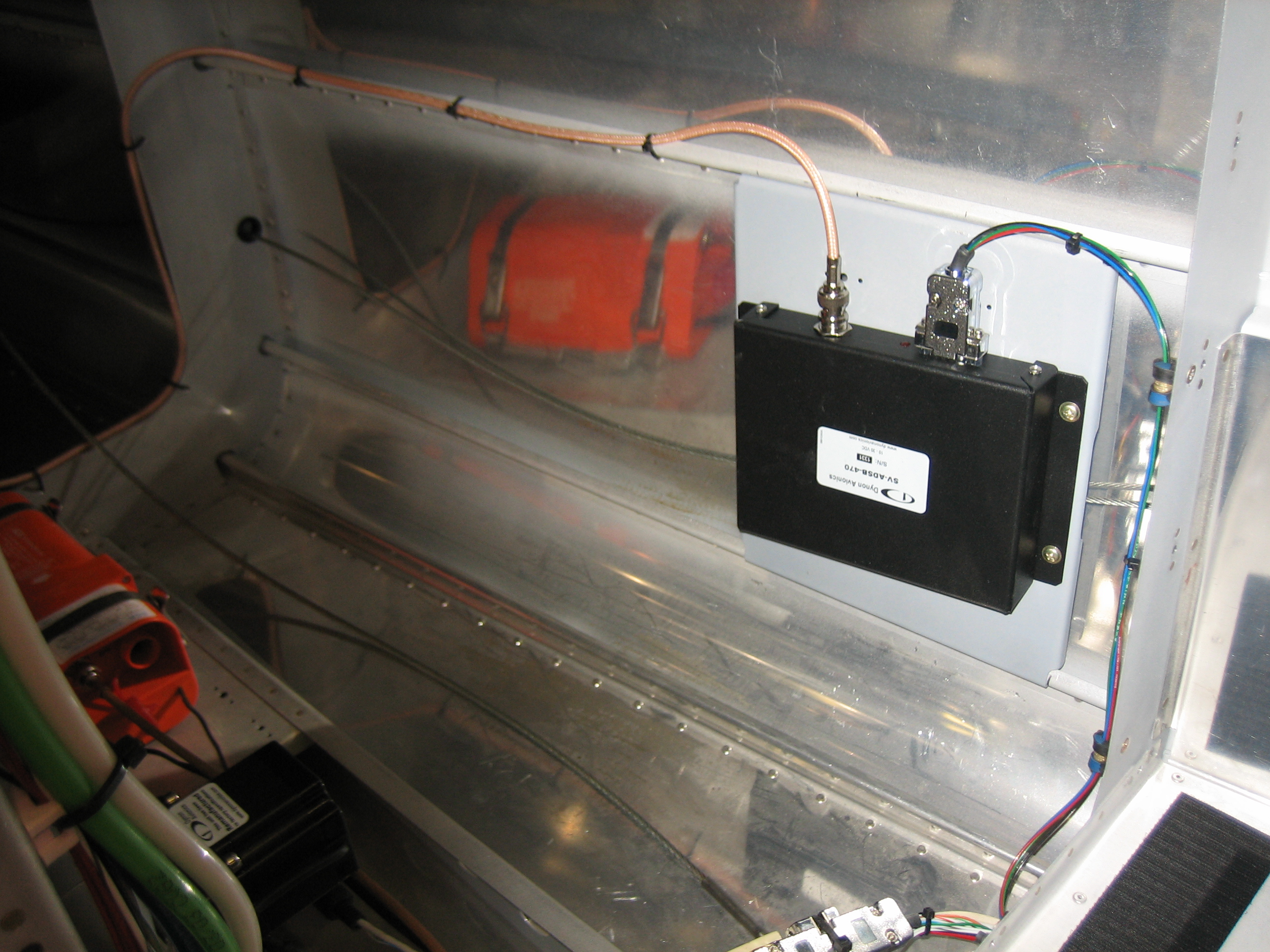
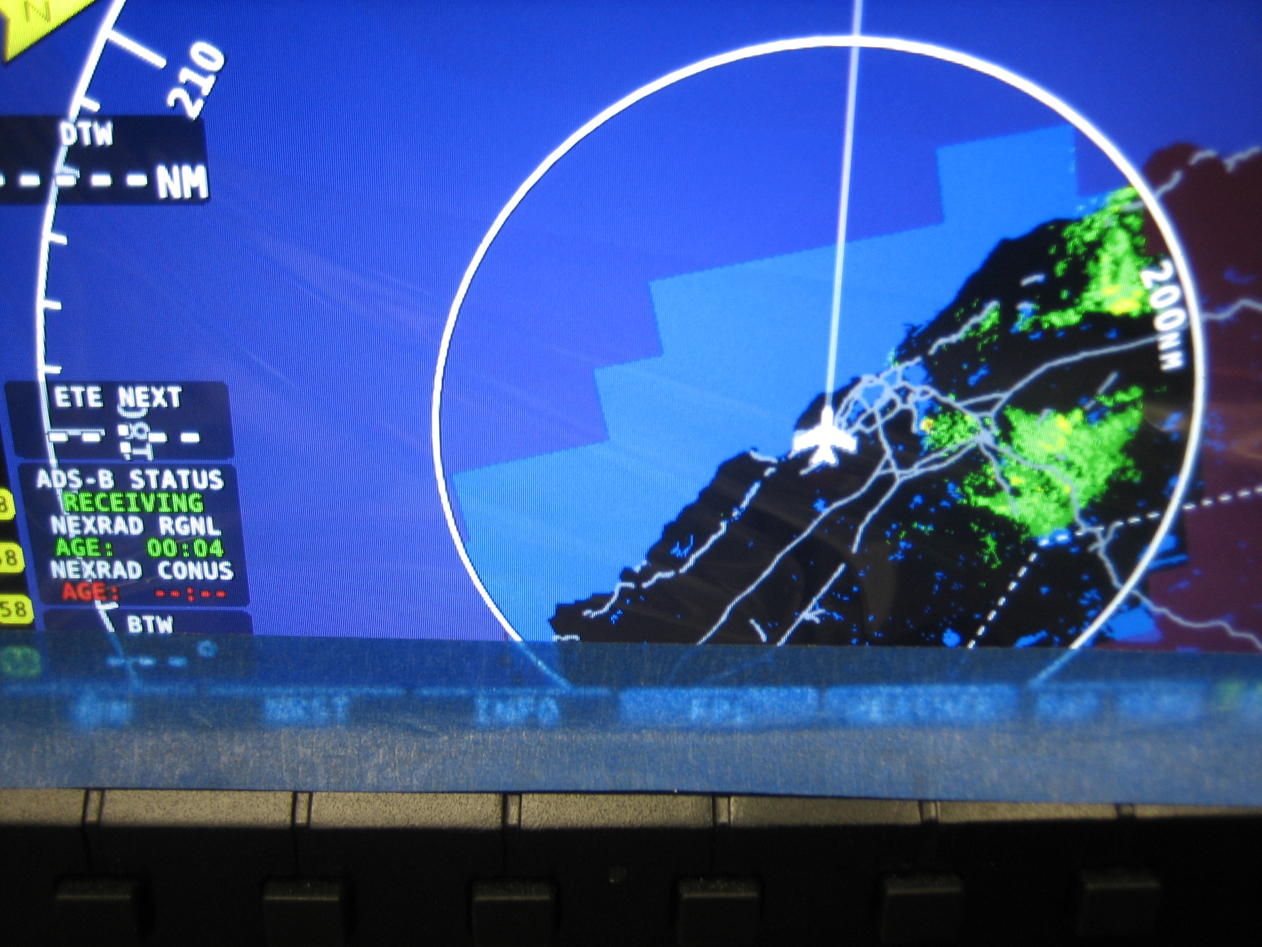
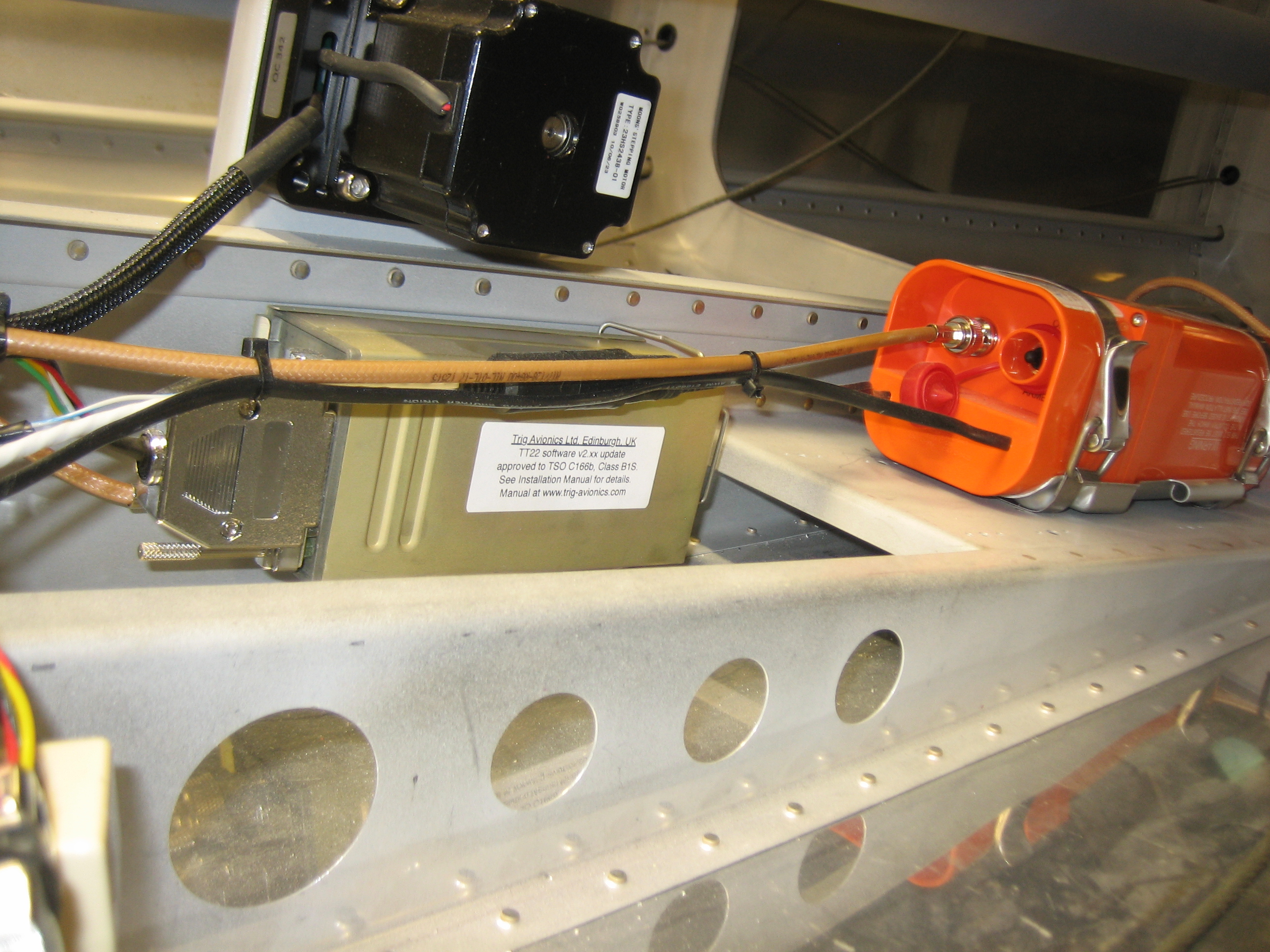
I also received the Dynon ADS-B receiver today and spent some time deciding where to mount it.  There’s basically no place up front that is easily accessible since I’m trying to make sure that every box in the plane can be accessed and removed if necessary.  I ended up deciding to order one of Van’s ELT mounts that fits between the left side stringers and mount it there.  It’s a fairly short run of coax from there back to where the UAT antenna will be mounted about 2′ behind the transponder antenna.

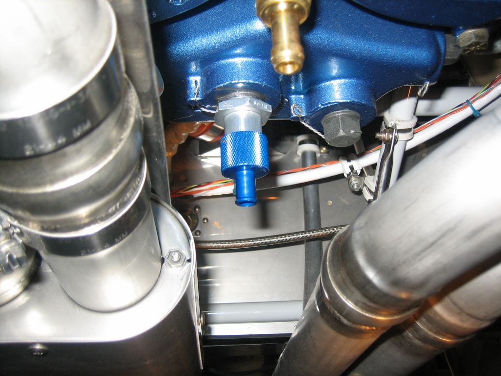
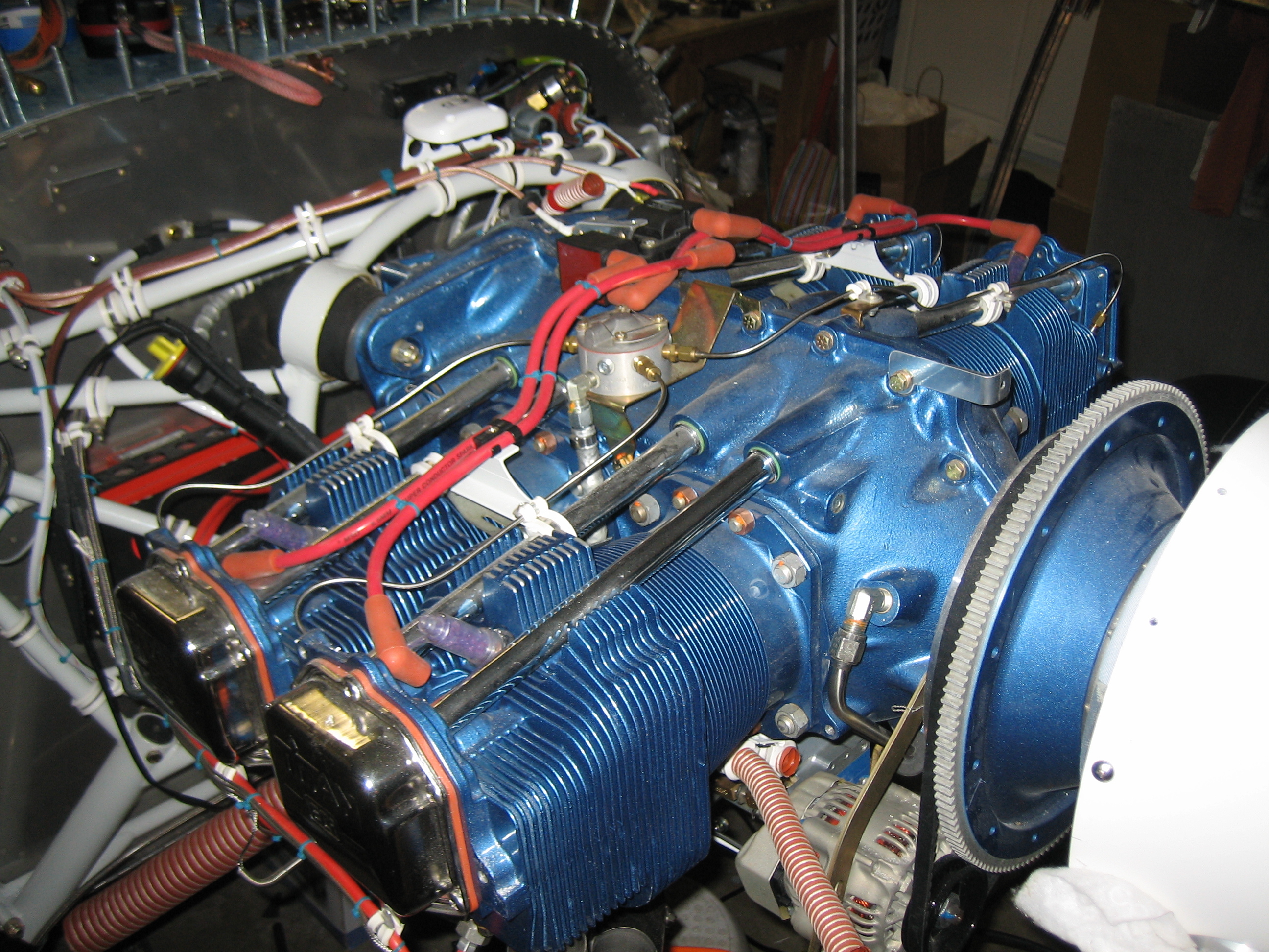
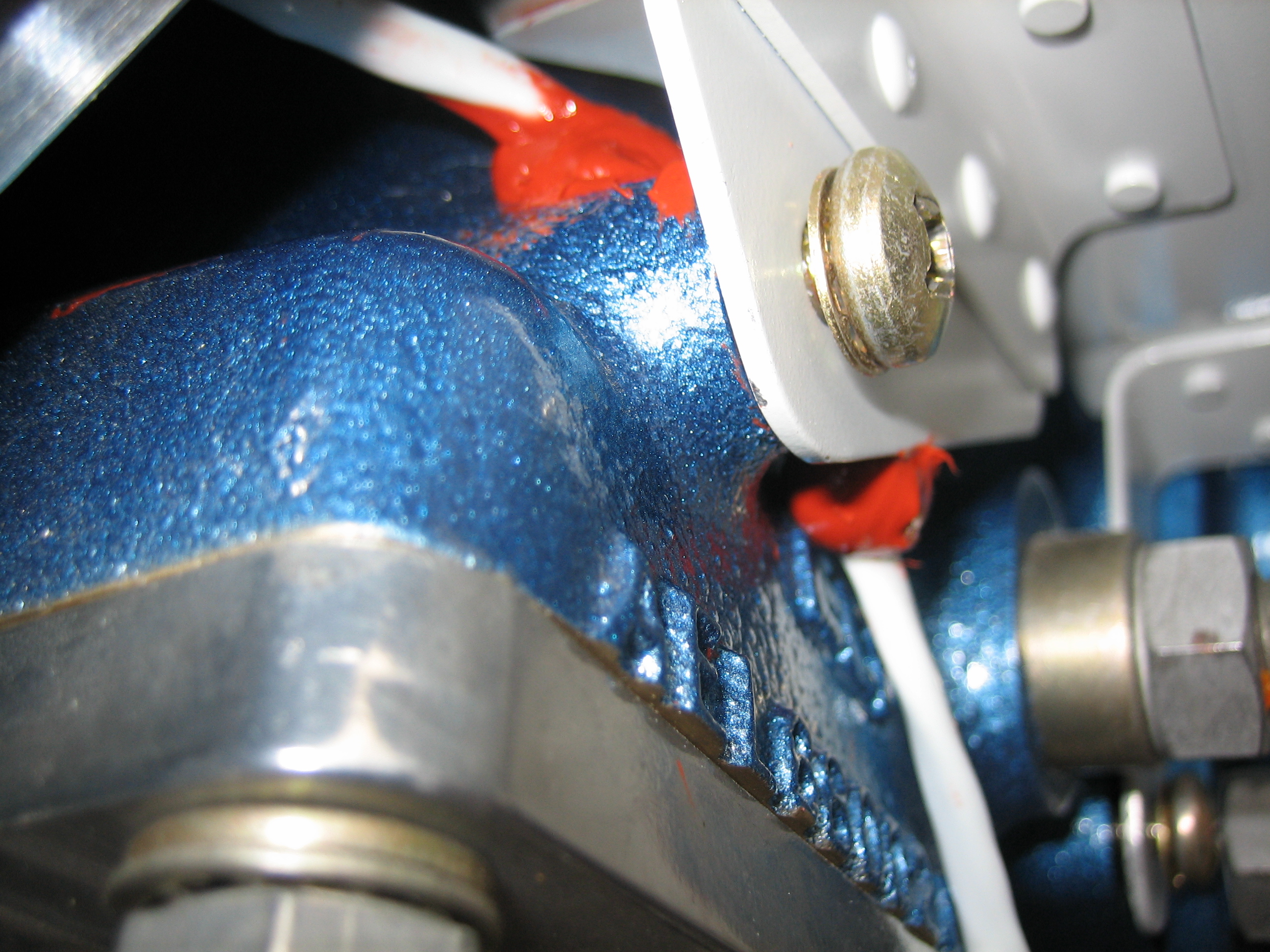
I decided to replace the Curtis quick drain on the right that came with my engine with the one from Saf-Air.  Not only is it better made, double sealed and rebuildable, but it’s 2 3/8 oz lighter!  That’s a huge weight savings for only $80.  There are other parts on the plane that I spent hours on trying to shave out less weight than this simple change.

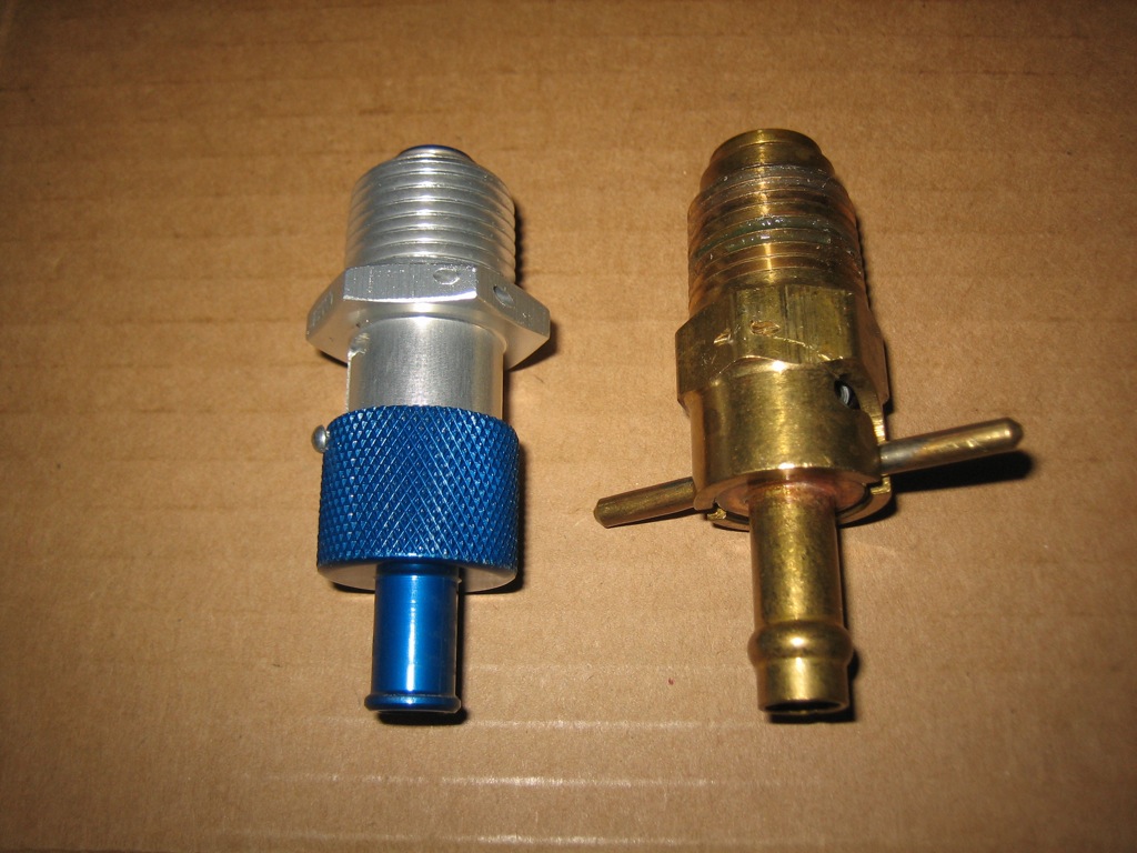
Here’s the valve installed and safety-wired.

Installed Baffles

With the baffles finished and the RTV cured, I reinstalled the baffles and installed all of the fasteners for good with lock washers.

Where the Lightspeed cable passes around the forward baffle attach bracket, I squirted a large blob of RTV sealant to keep the cable away from the flywheel and the bracket.

With the baffles installed for good, I installed the Lightspeed primary ignition wires.

Mounted ADS-B Receiver

I installed the nutplates on the mounting bracket and then put a coat of self-etching primer on it.  I had to fabricate a little spacer to be able to set the LP4-3 rivets since the flange of the stringers prevent the nose of the hand riveter from fitting down flush against the top of the rivet.

I fabricated a small antenna doubler for the UAT antenna, then drilled it to the bottom of the fuselage.  I mounted this 2′ aft of the transponder antenna, just behind the next bulkhead and right on the aircraft centerline.

Finished Installing ADS-B Receiver

Jenn came out and helped me rivet the UAT antenna doubler and install the antenna.

I fabricated the antenna cable and installed it.  It routes along the bulkhead and then…

up to the stringer and forward to the receiver.  I also installed the power, ground and serial lines.

Finally, I fired it up and was able to get weather even sitting in my garage.  I only waited long enough to let the regional weather load, but you can see the storms out to the north 100-200 miles away.  You can see in the lower left corner that the regional weather is 4 minutes old and it’s still receiving.  With this done, I’m finished with the avionics (for now at least).

Updated Transponder to Full ADS-B Out Compliance

Included with the SkyView 5.0 software update is an update to the transponder that moves it from TSO C166a to TSO C166b compliance.  This means it’s fully compliant with the 2020 ADS-B mandate for 1090ES.  Installing the software update requires that the transponder be simultaneously labeled to indicate TSO C166b approval.  Apparently, not applying the label renders the transponder unairworthy according to the FAA.