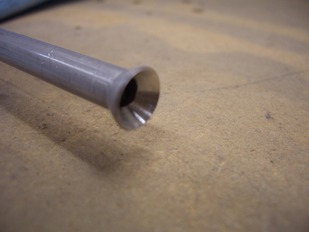
I fabricated the tank vent lines tonight. These are the lines that will let air back into the tank as fuel is pumped out during flight. First up was to flare one end of the 1/4″ tubing using the Parker Rolo-Flair flaring tool. This will flare aluminum, copper, and stainless steel in sizes ranging from 1/4″ to 3/4″.
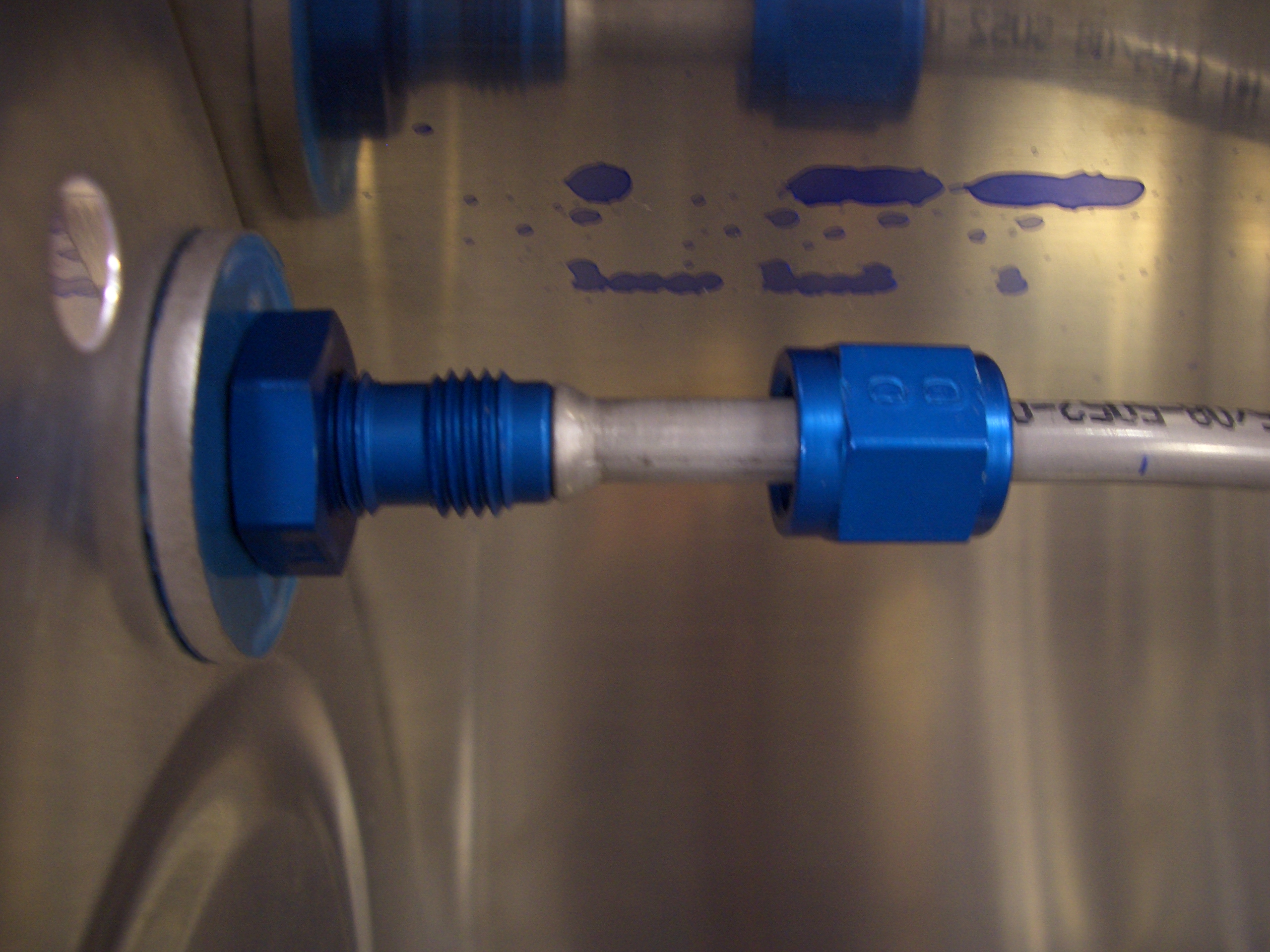
Here is what one of the flares looks like on the 1/4″ aluminum tube. I’m using 5052 tubing instead of the 3003 tubing that comes with the kit. It seems to be easier to work with and isn’t as prone to cracking when flared.
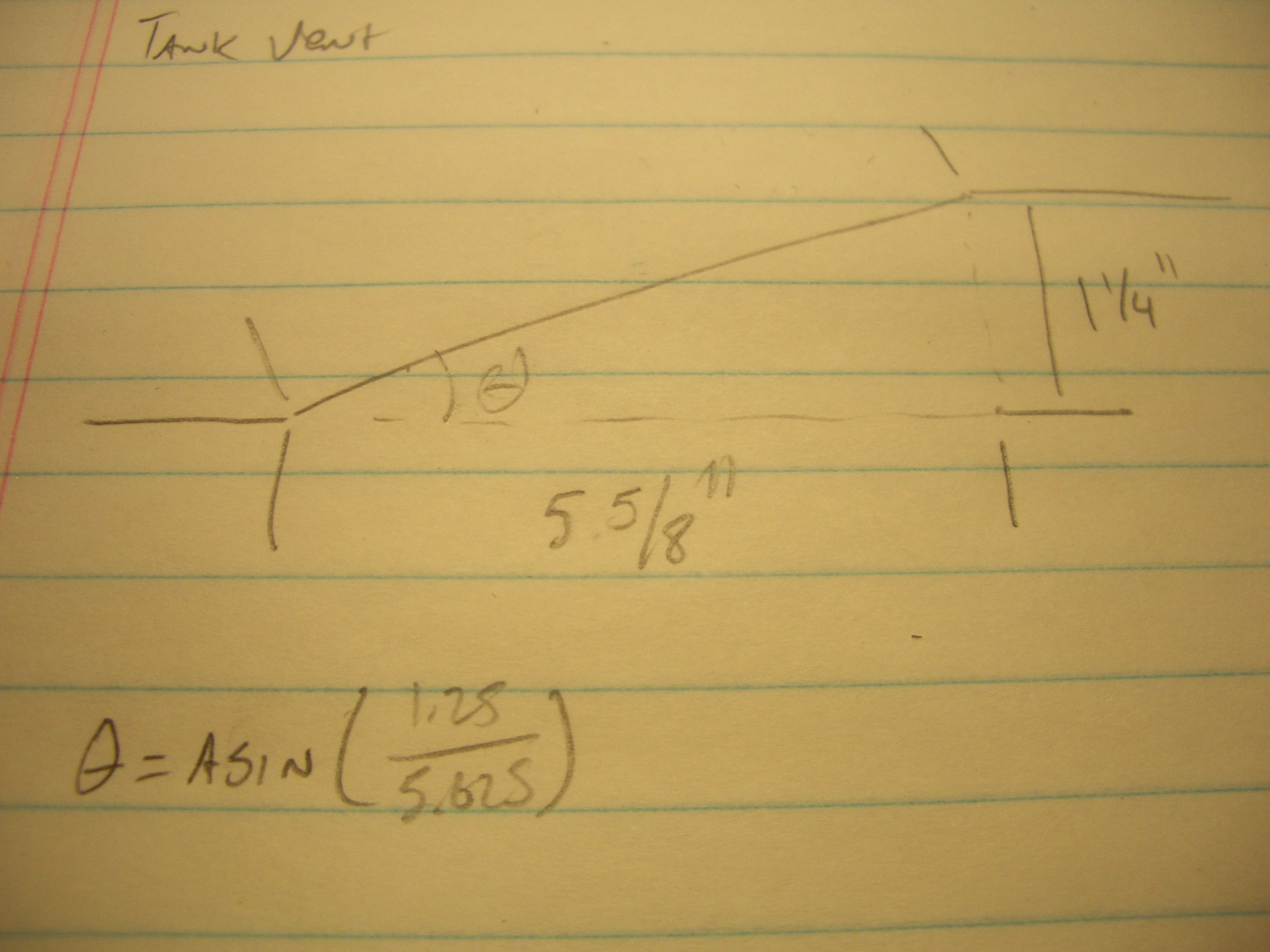
The holes that the vent line passes through the interior ribs doesn’t line up with the fitting in the end rib (I had to move it over to make room to mount the fitting. The tube has to jog over 1 1/4″ in the inboard bay. I needed a little bit of straight tubing at the fitting, so I determined that the jog could take up 5 5/8″ of the inboard bay. A little quick trigonometry (arctan of 1 1/4 divided by 5 5/8″) yielded about 13º for the bends (I know I wrote arcsin below. Give me a break; it’s been 20 years since I used this stuff. I’m entitled to be a little rusty).

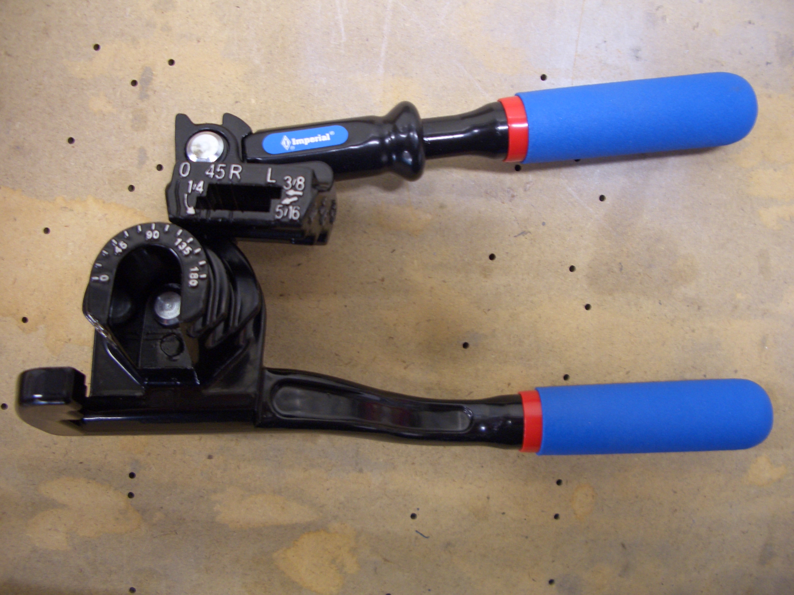
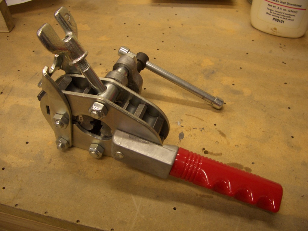
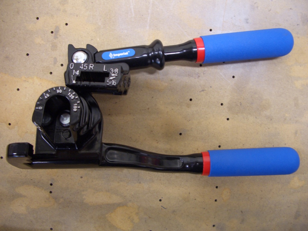
Here is the bending tool I’m using. It’s an Imperial 470FH. It can do 180º bends in 1/4″, 3/8″, and 1/2″ tubing.
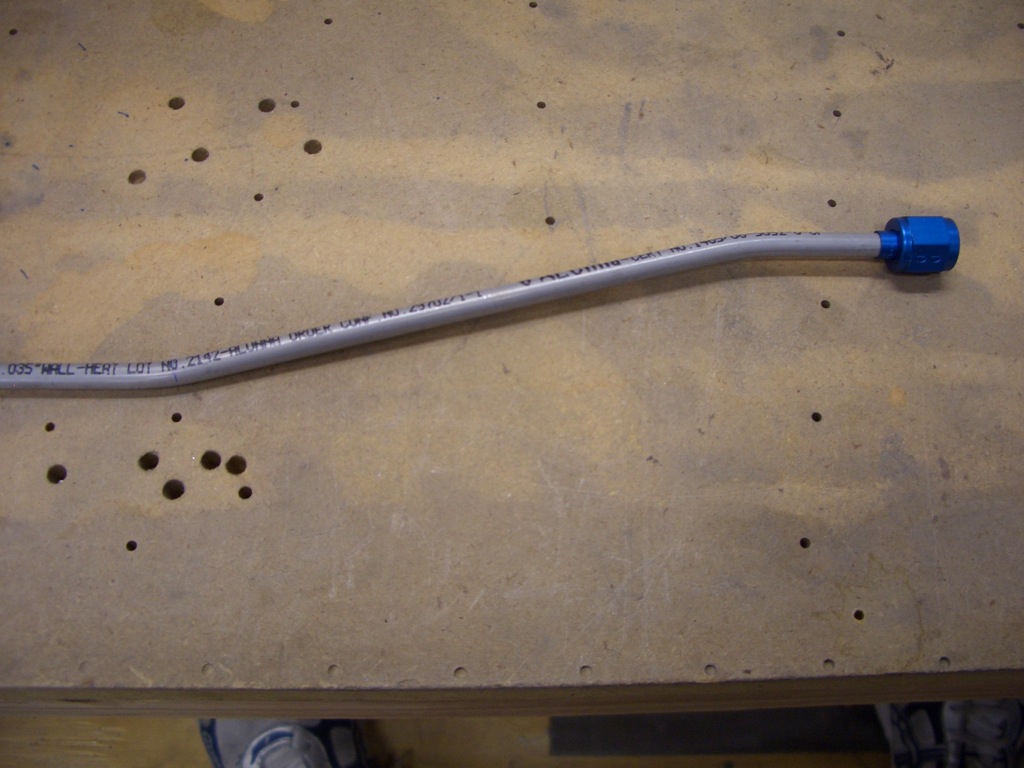
And here is the resulting shape in tubing.
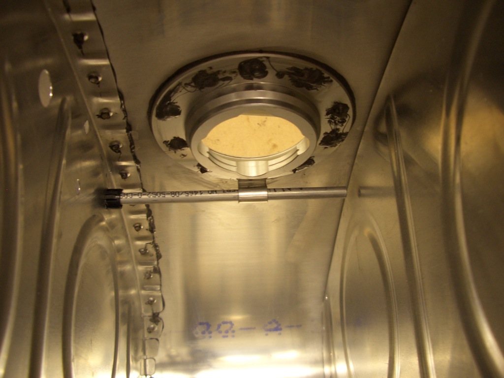
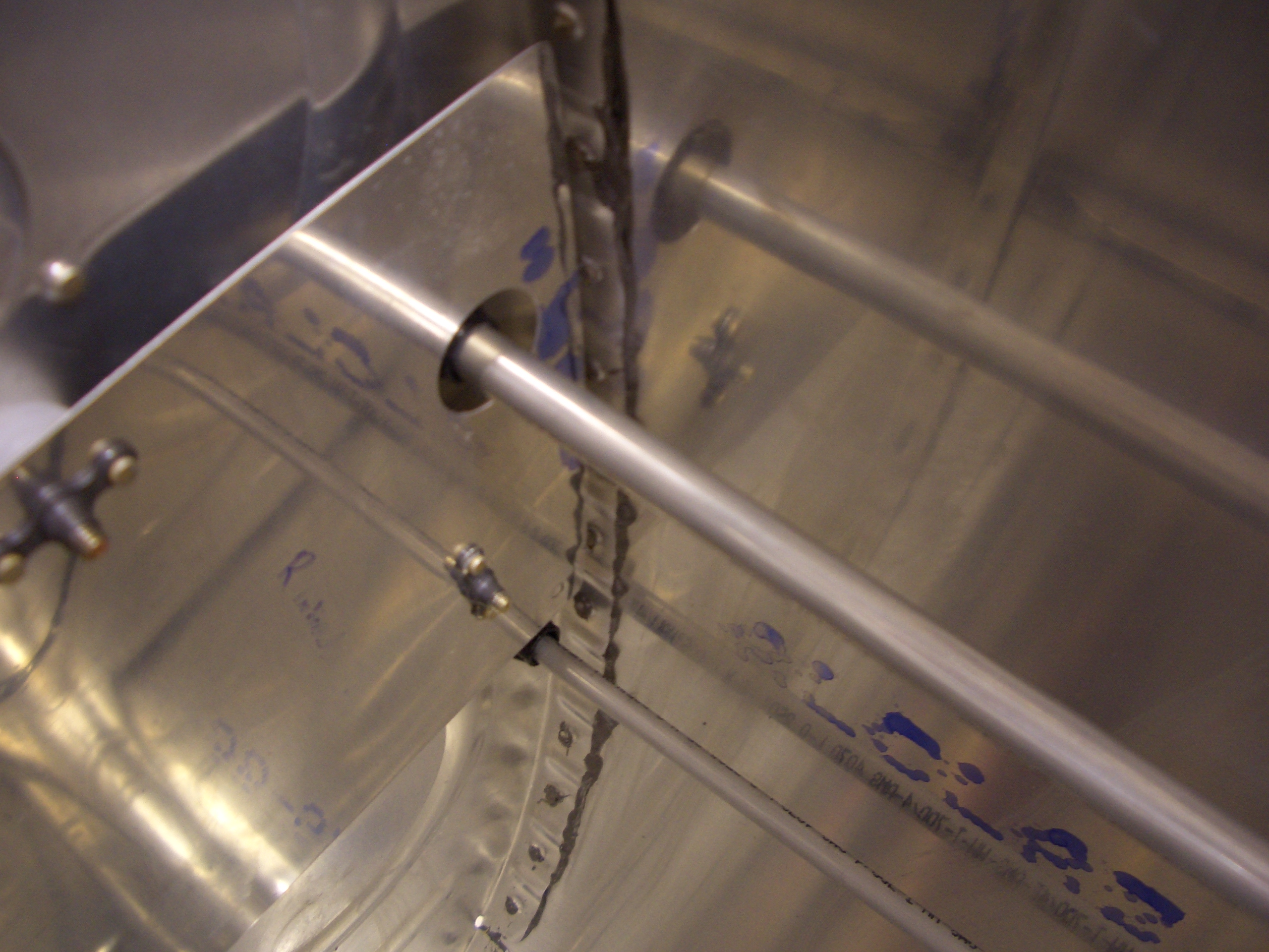
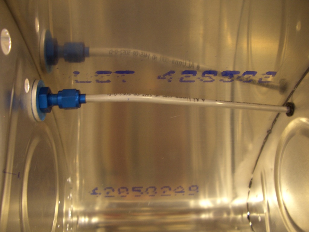
You can see how accurate the bend was here. The flare lines up perfectly with the fitting without having to use any force to hold it there.

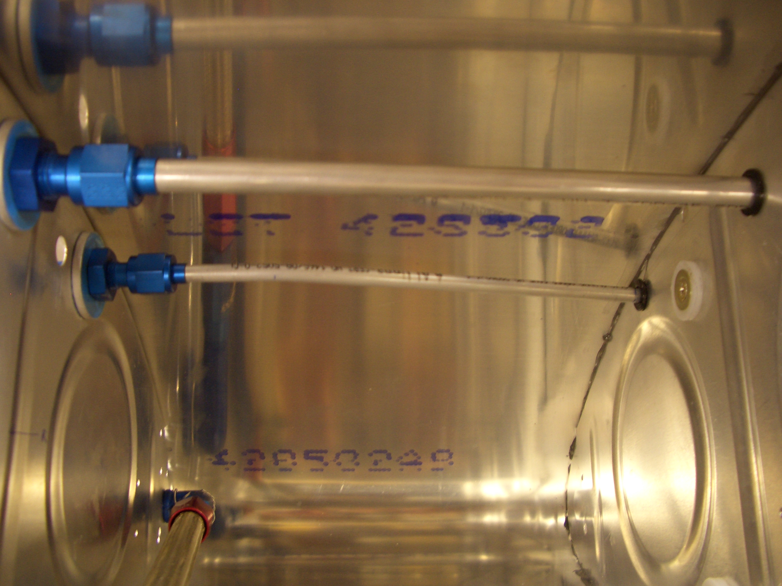
Here’s what the inboard bay looks like. You can see that the bend goes almost all the way to the second rib.
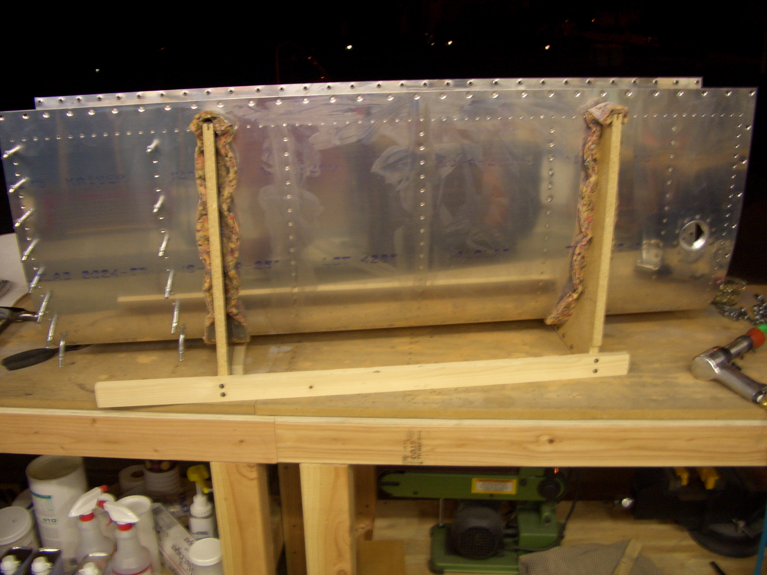
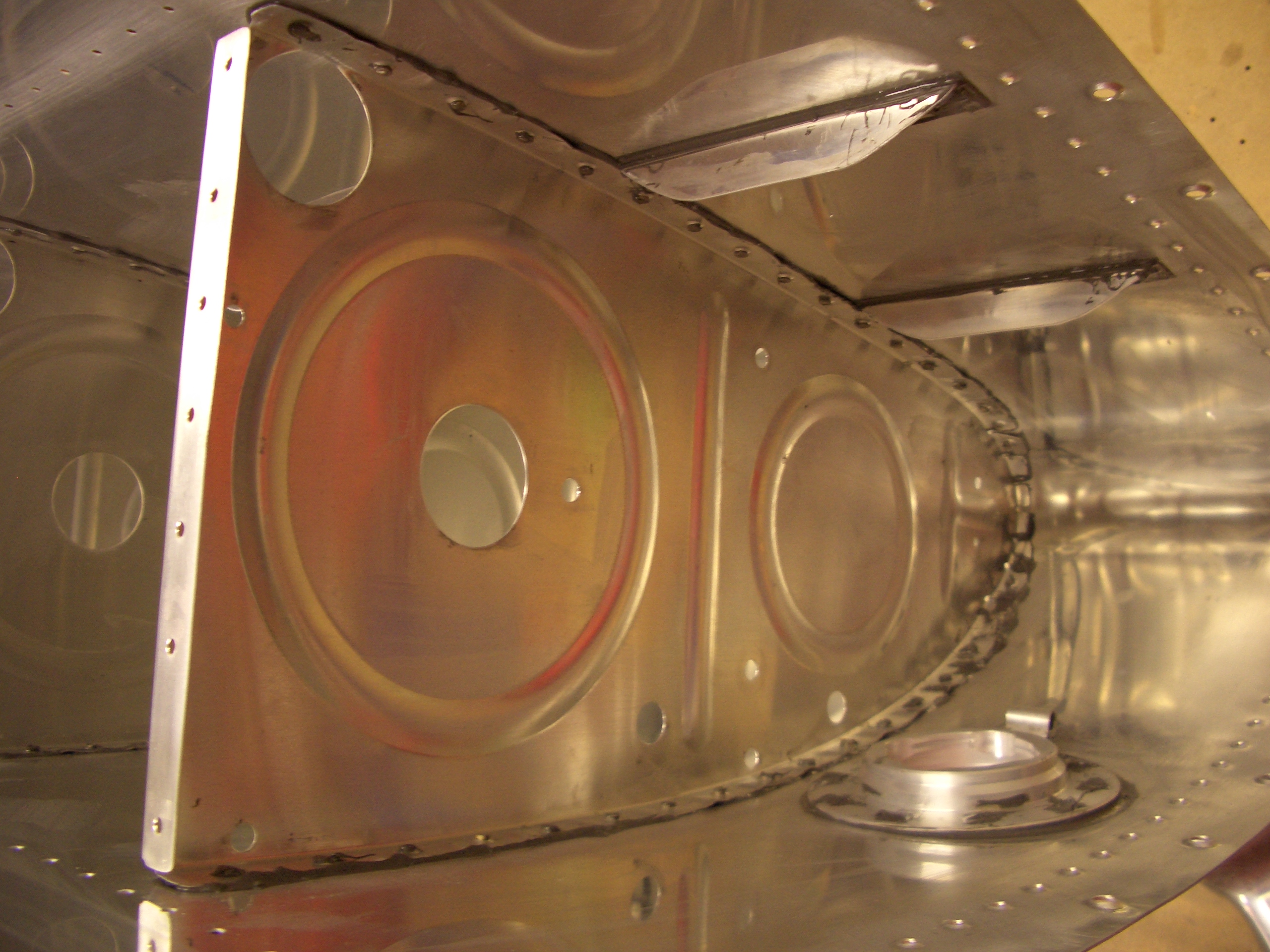
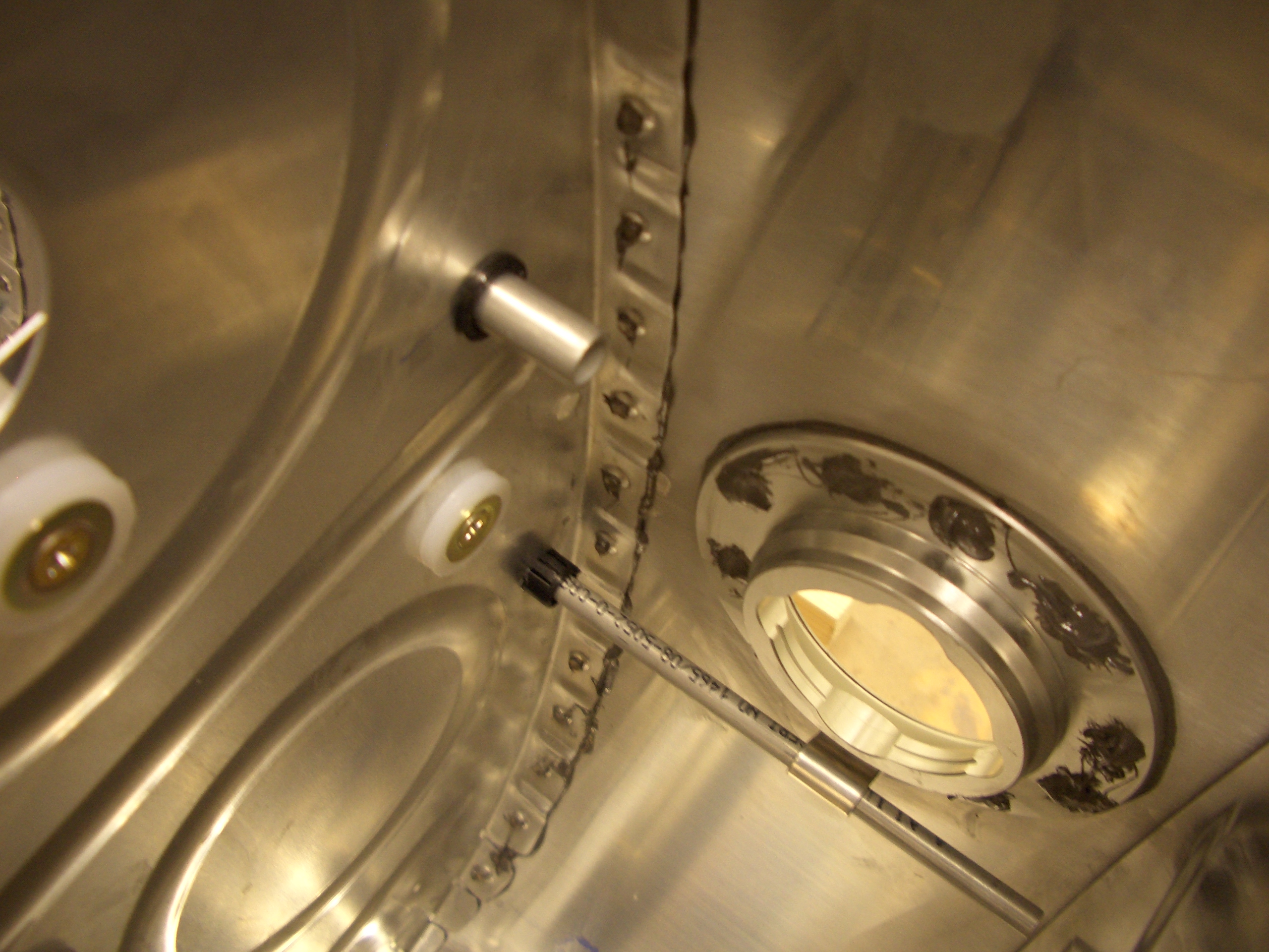
Here is the outboard bay. You can see how the clip I fabricated earlier supports the tubing. I’ll give a slight upward bend to the end of the tube after installing this for the last time to get the end of the tube as high up in the tank as possible. After spending about an hour fabricating this for the right tank, it only took about another 20 minutes to repeat the process for the left tank.