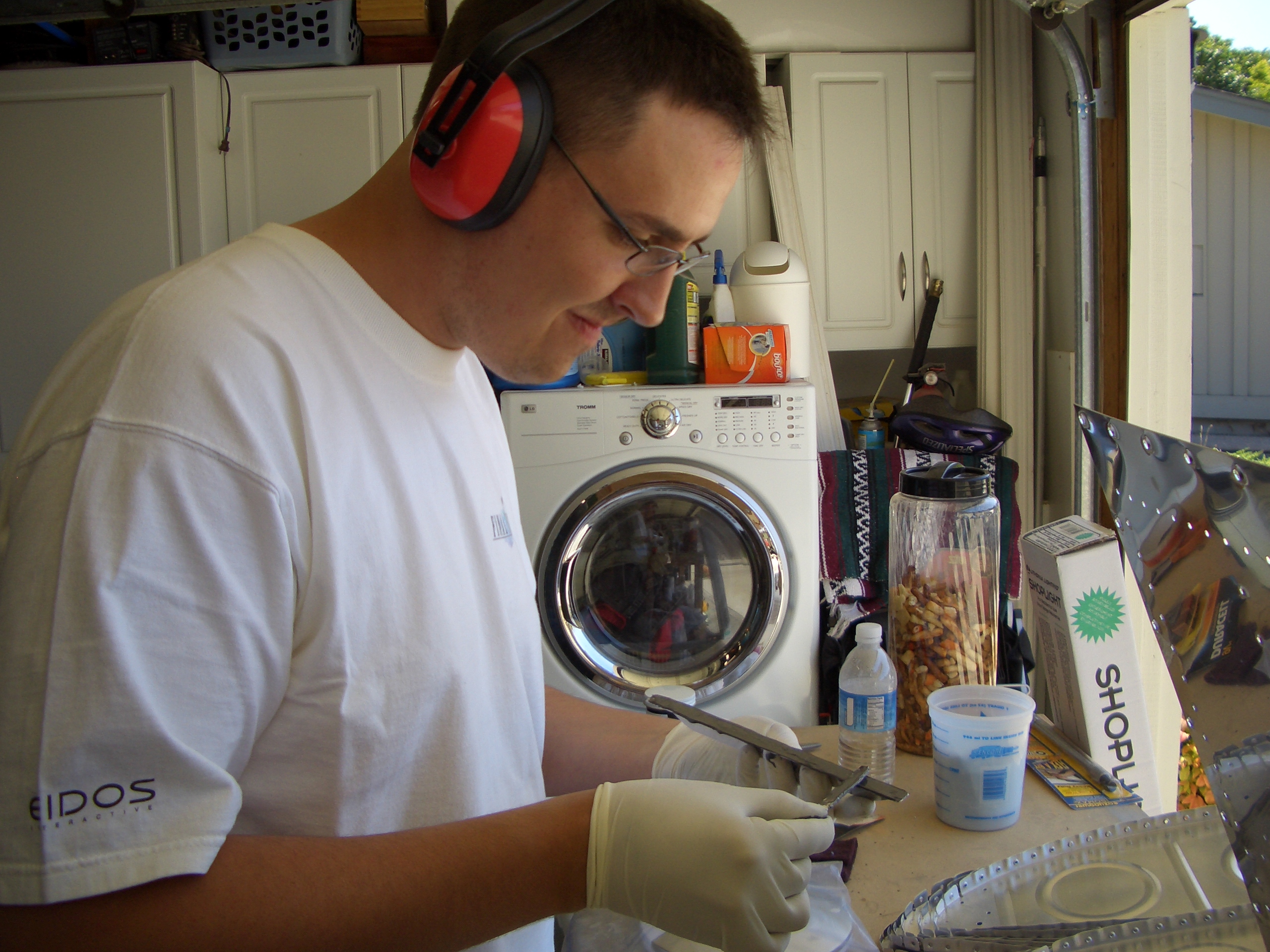
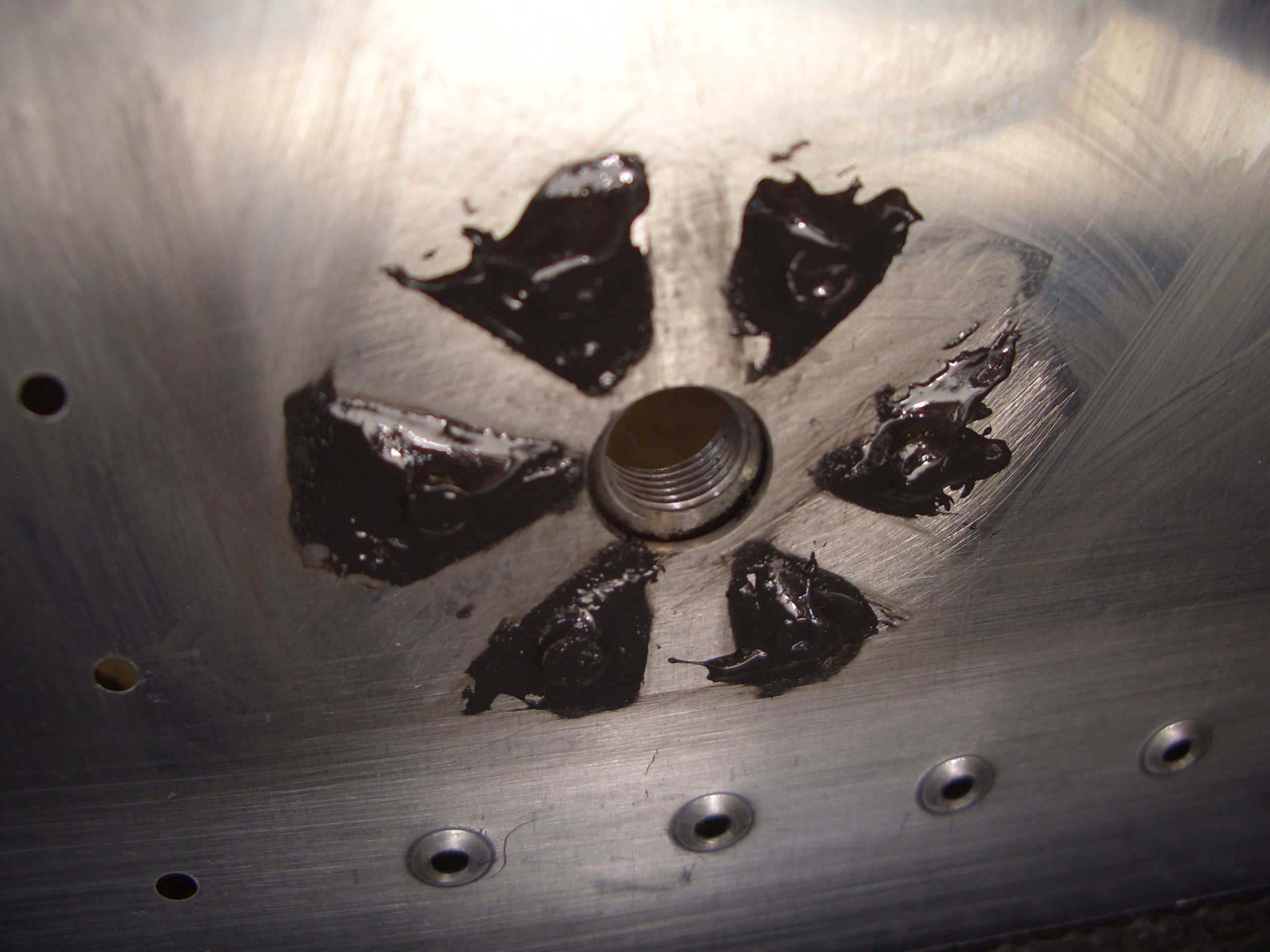
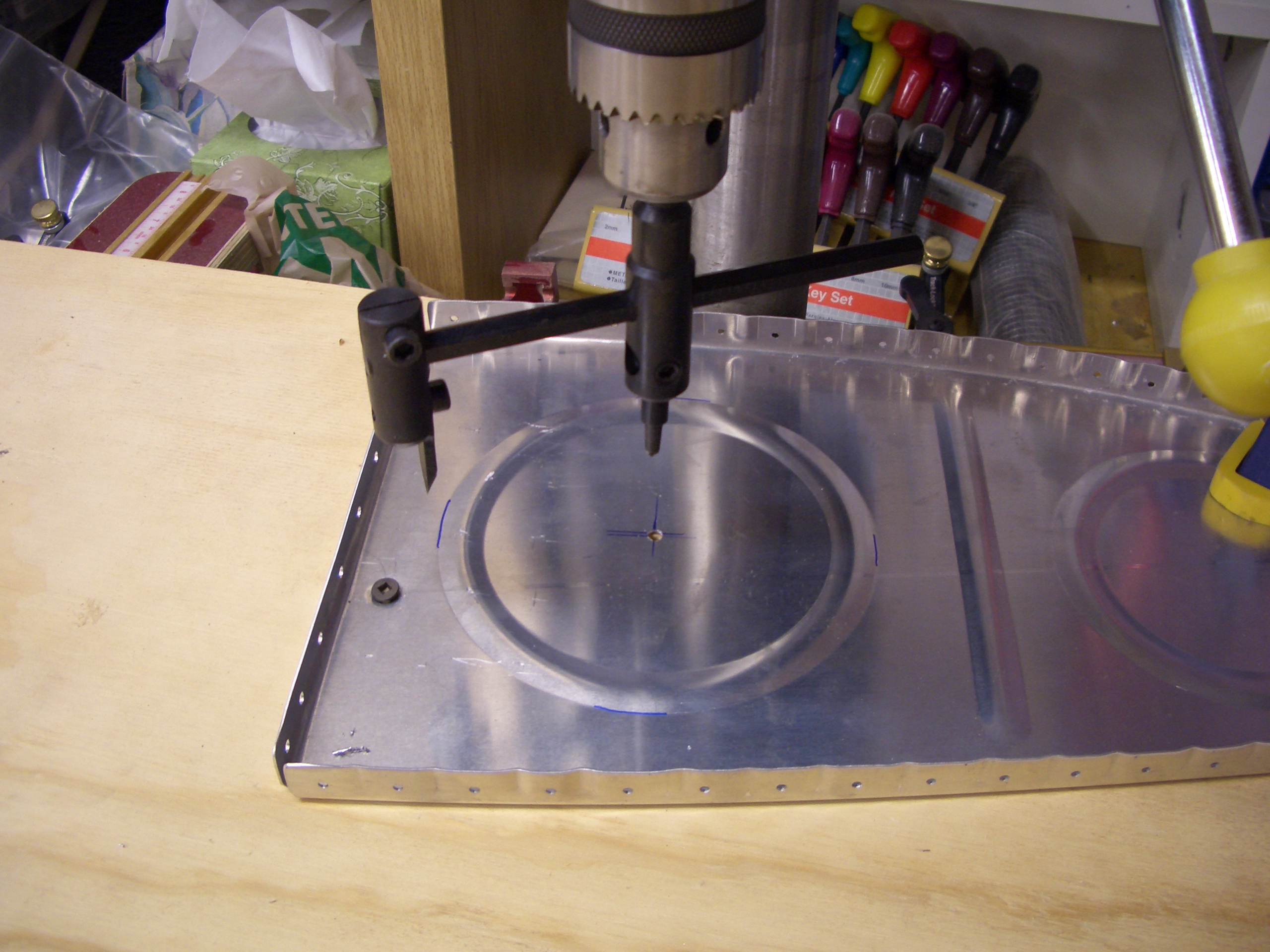
Per the plans, I modified the inboard ribs in each tank so that the inside of the tank can be accessed if the need ever arises. First up is to cut out the largest stiffener ring. I used this piece of shit fly cutter from Harbor Freight. It eventually worked, but this thing sucks and is going in the trash as soon as I buy a quality replacement.
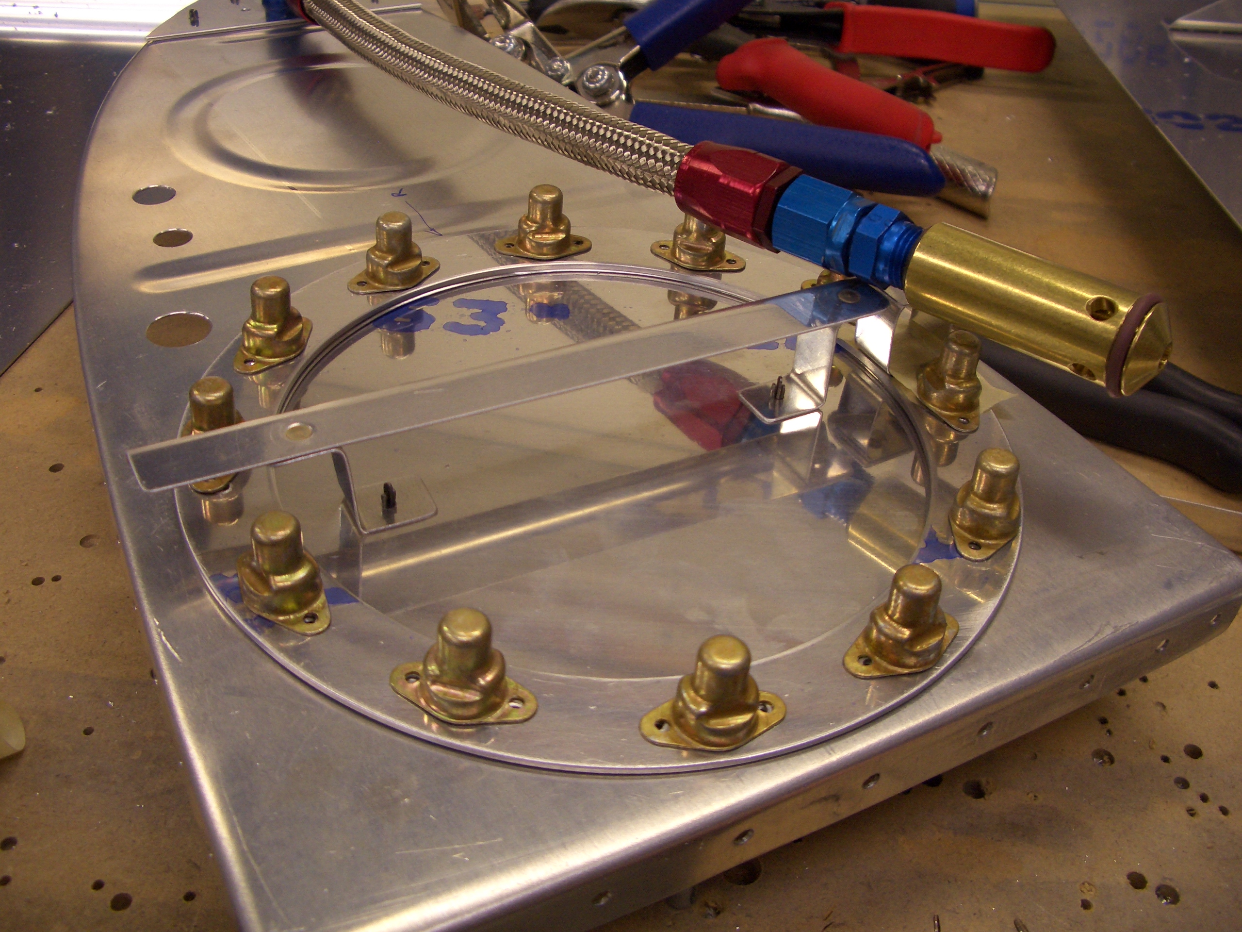
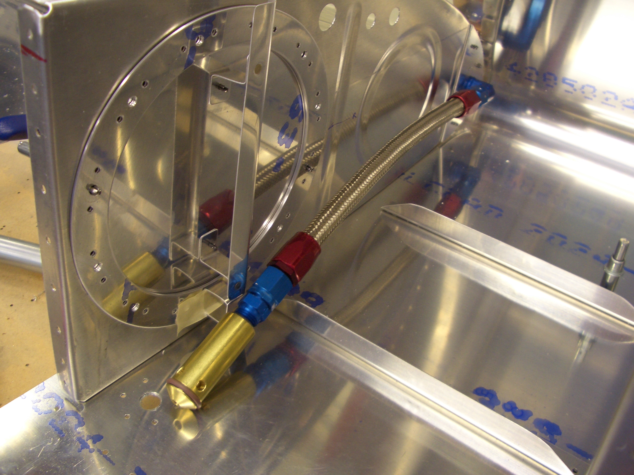
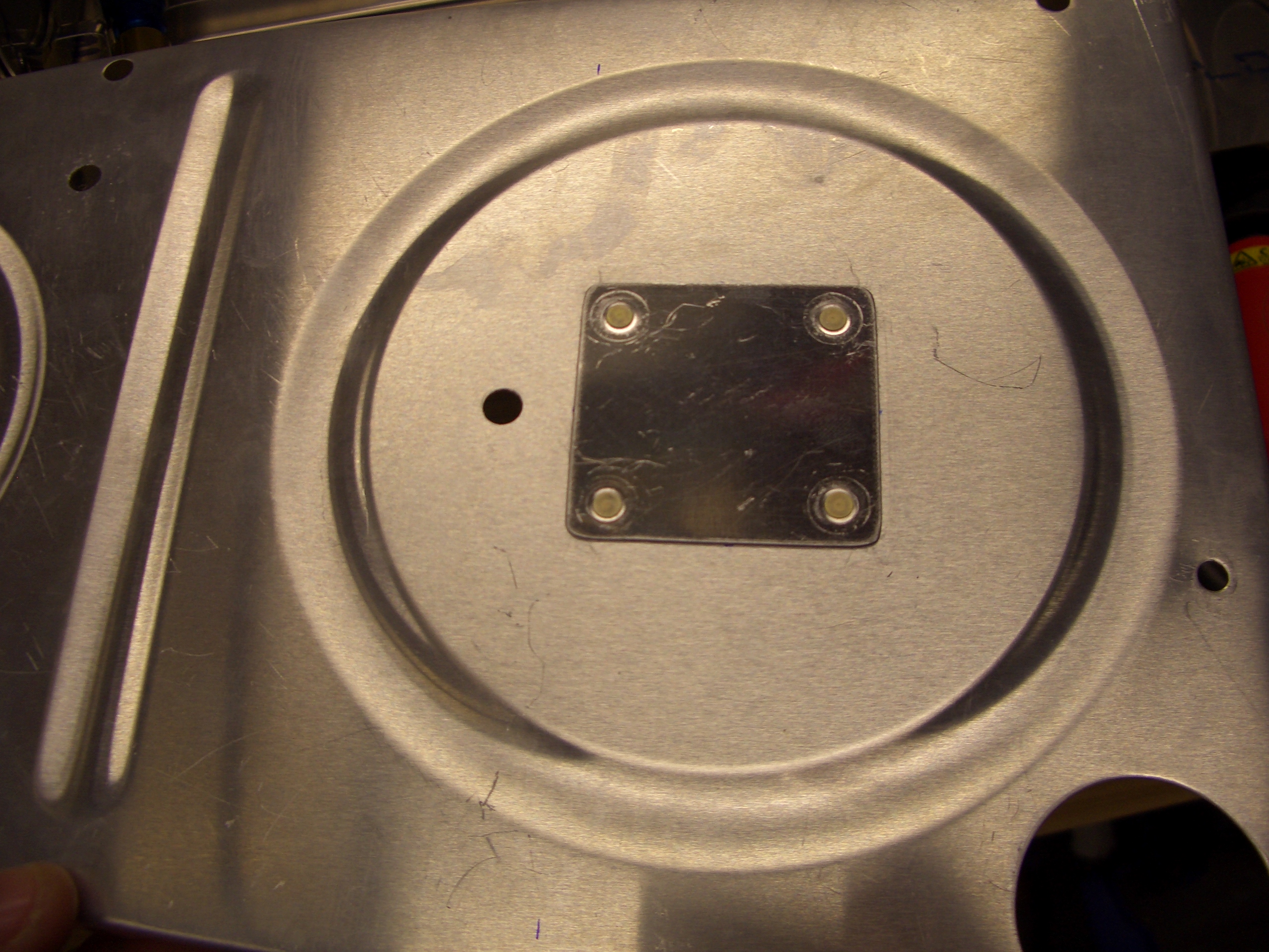
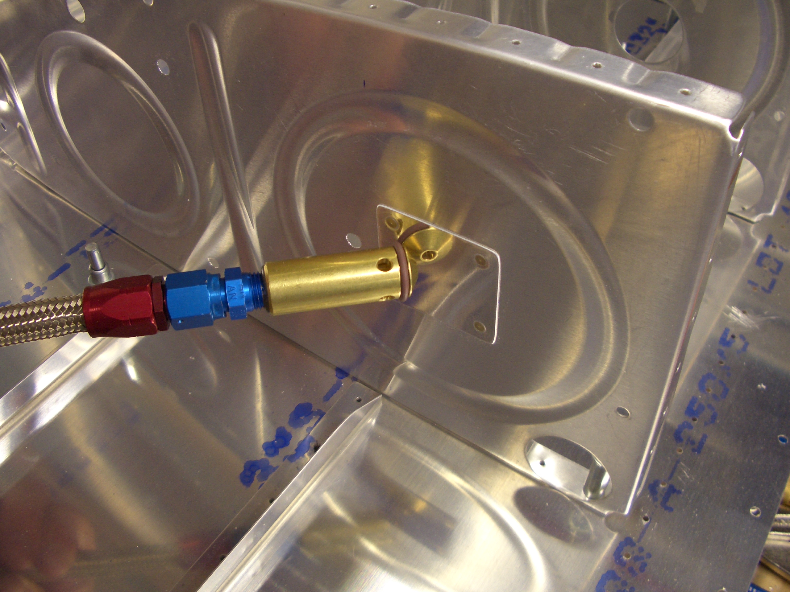
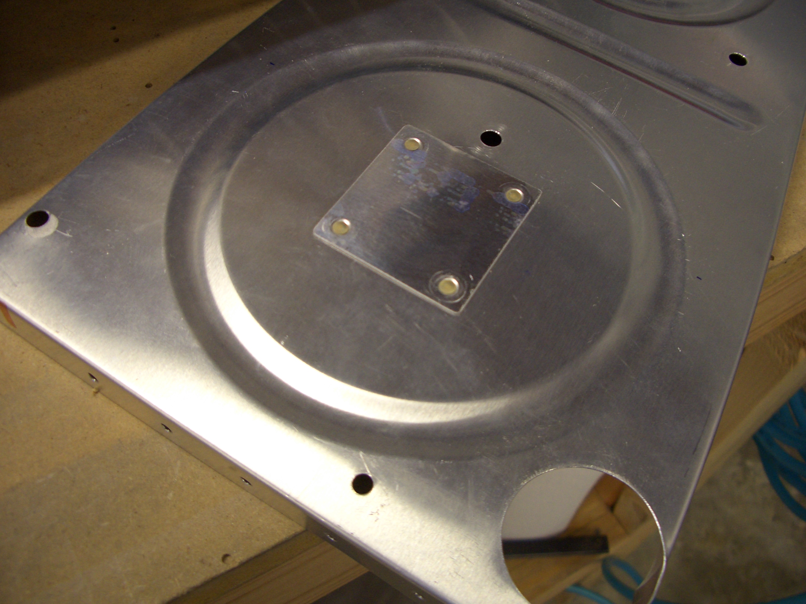
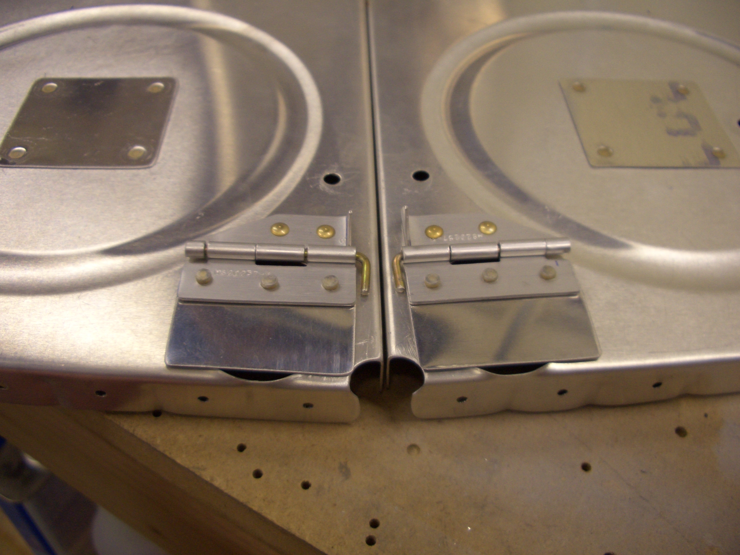
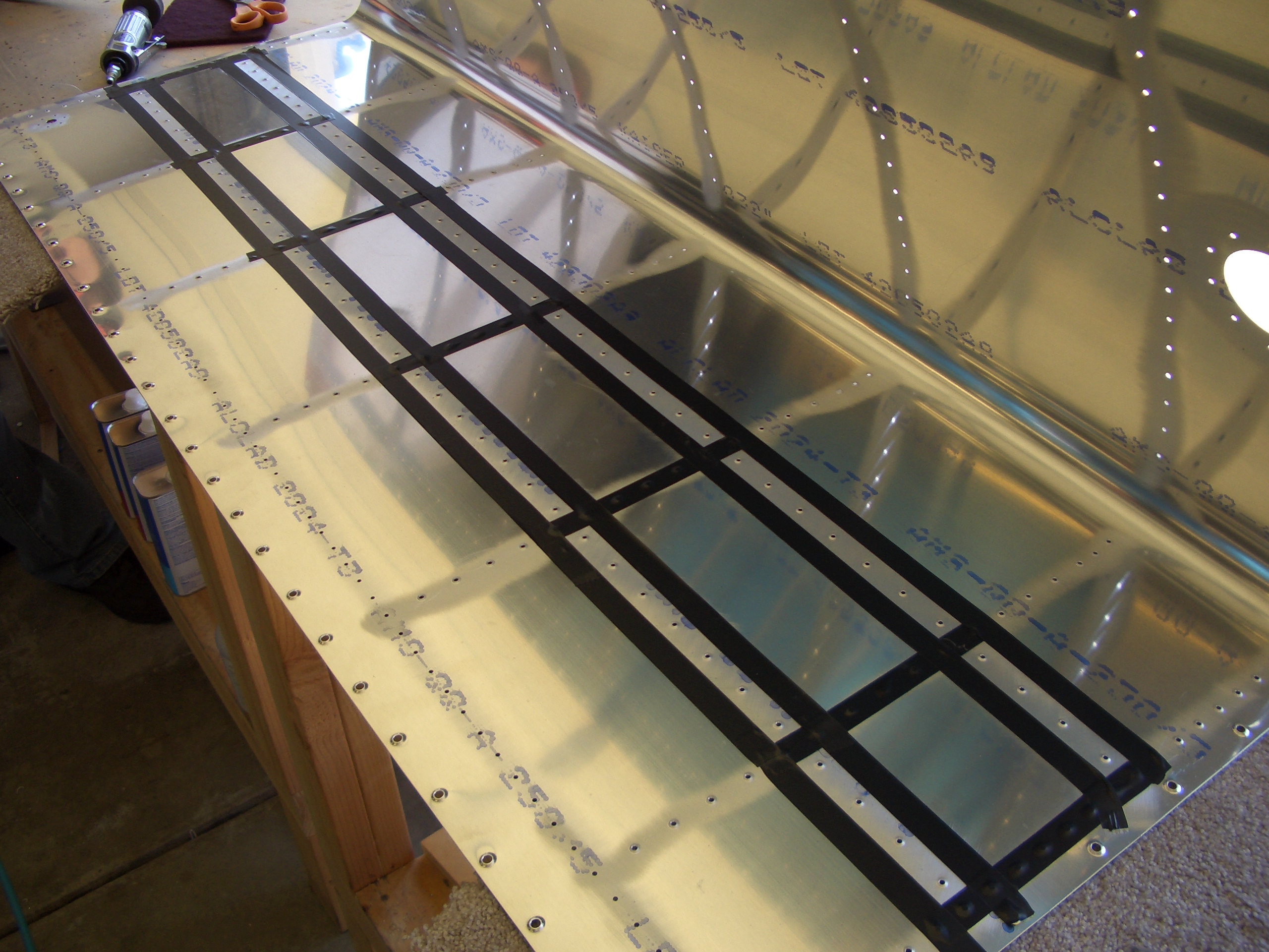
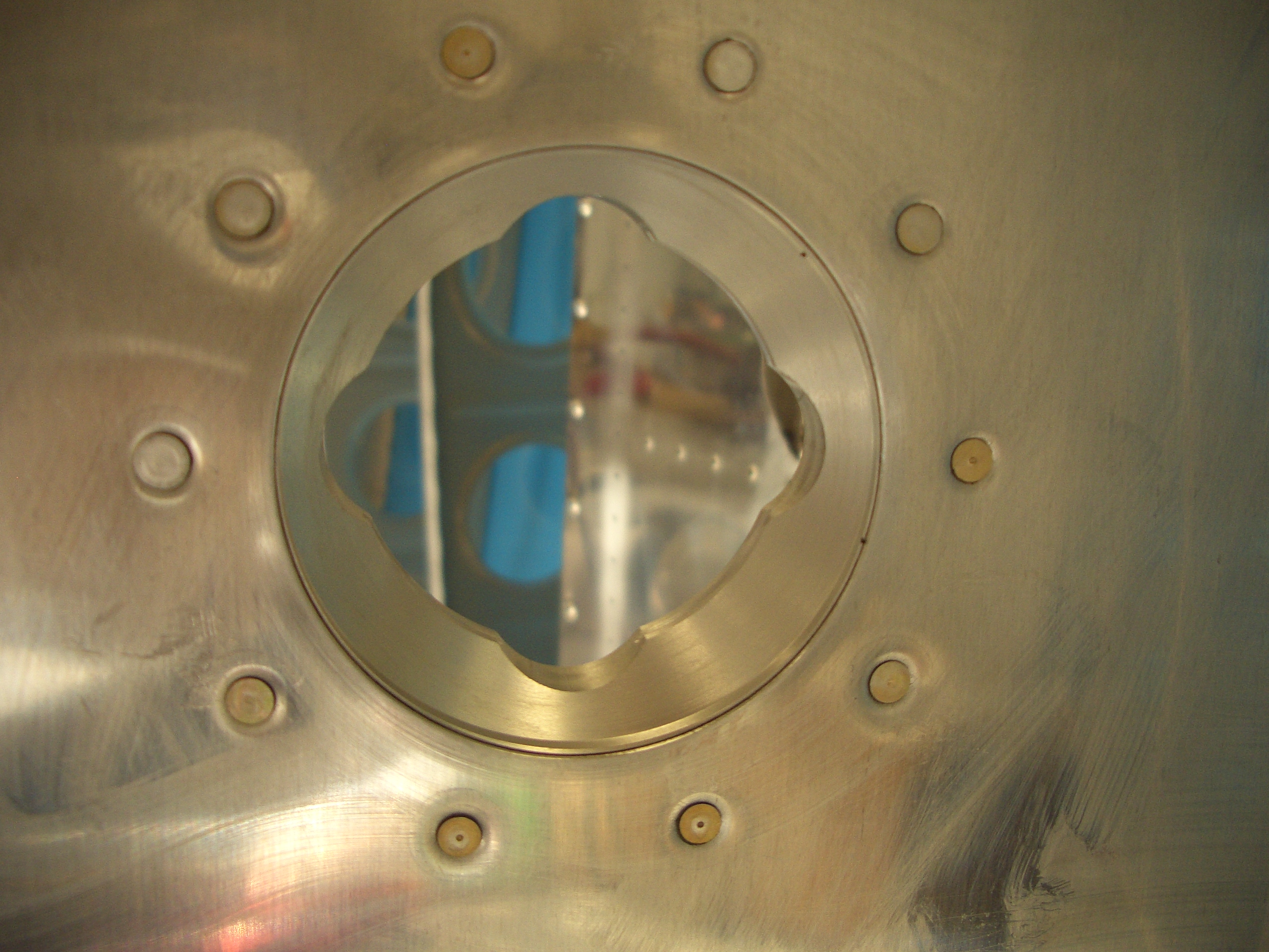
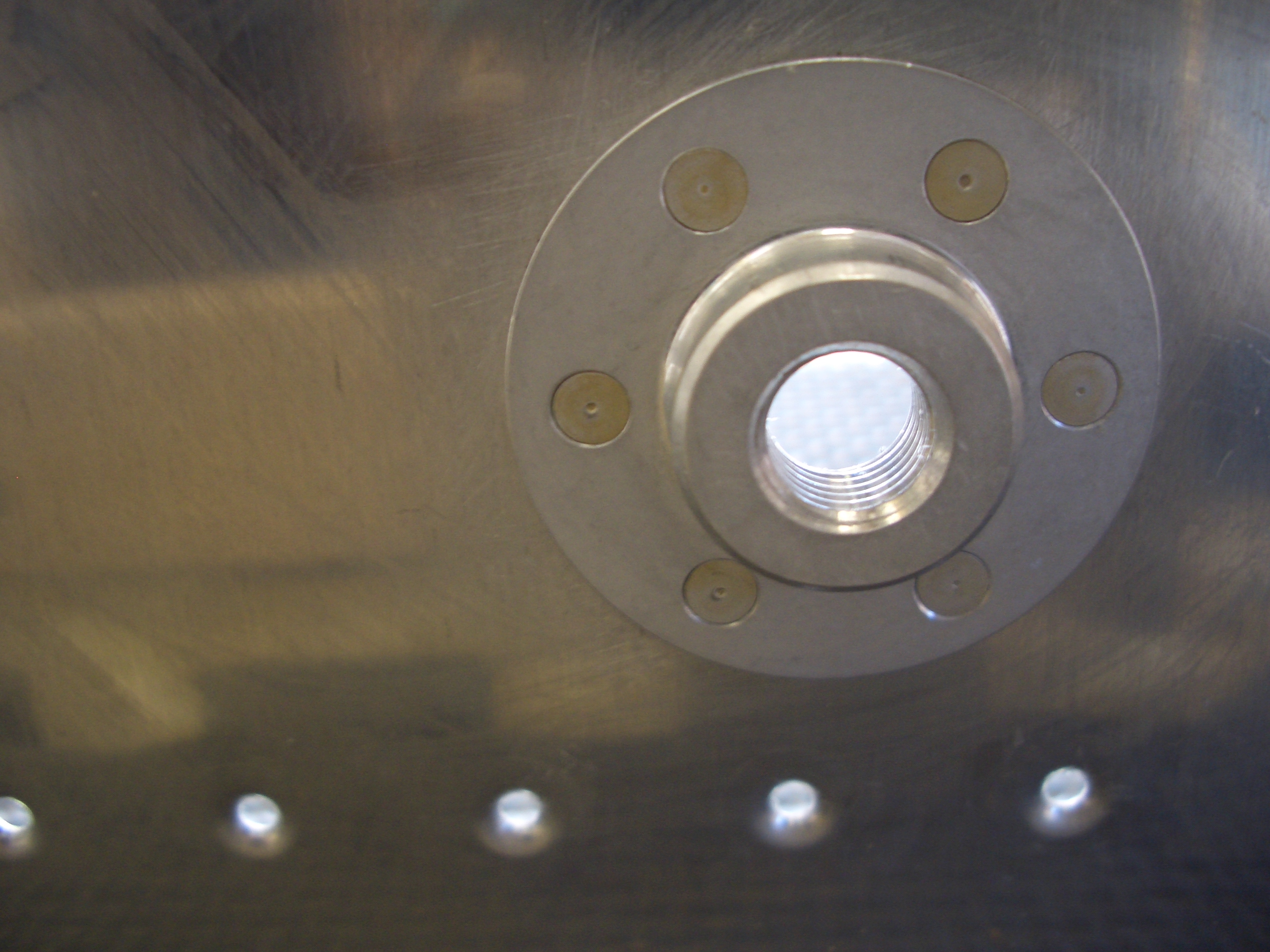
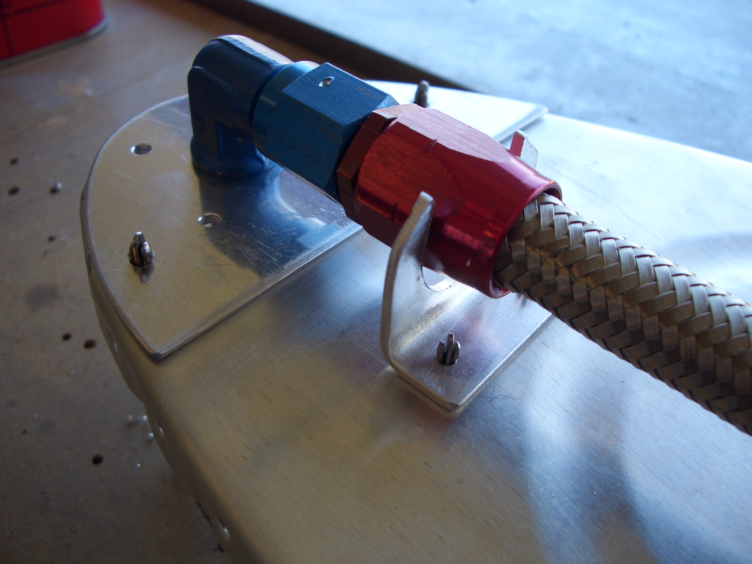
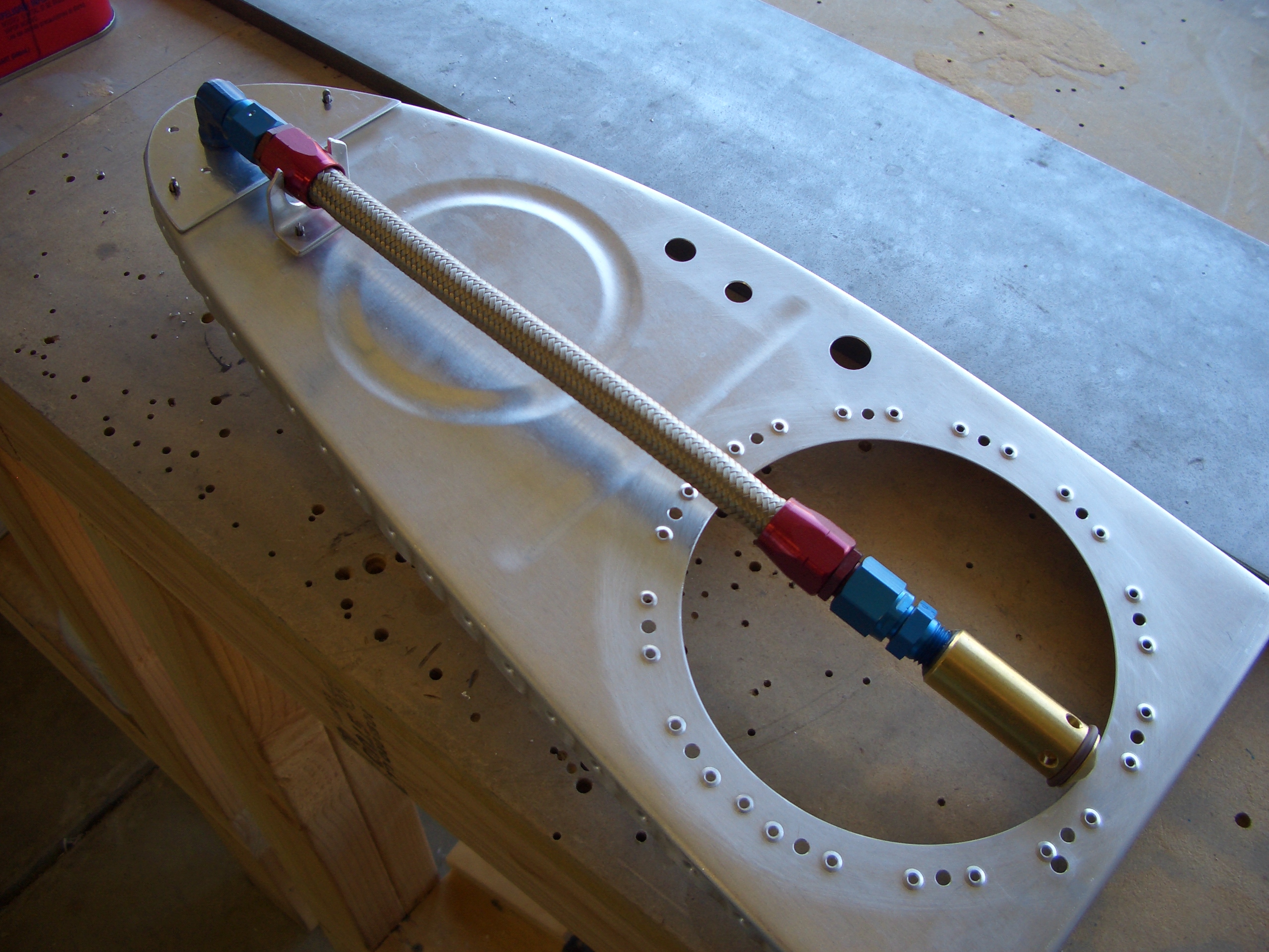
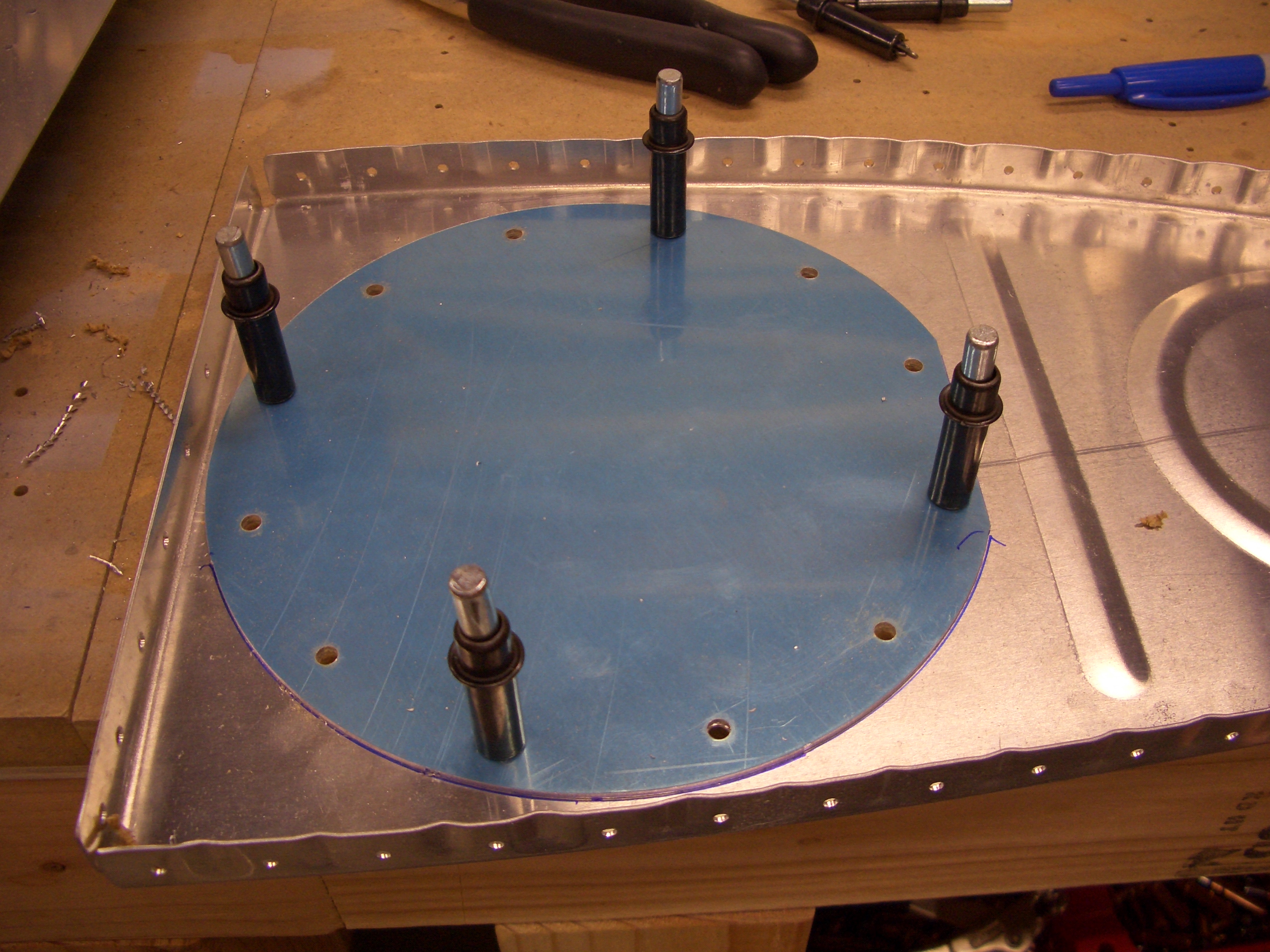
After the hole is cut out and deburred, the access plate is positioned and match drilled to the rib. Since I’m going with the capacitive fuel sender and flop tubes, this plate won’t have any holes through it.
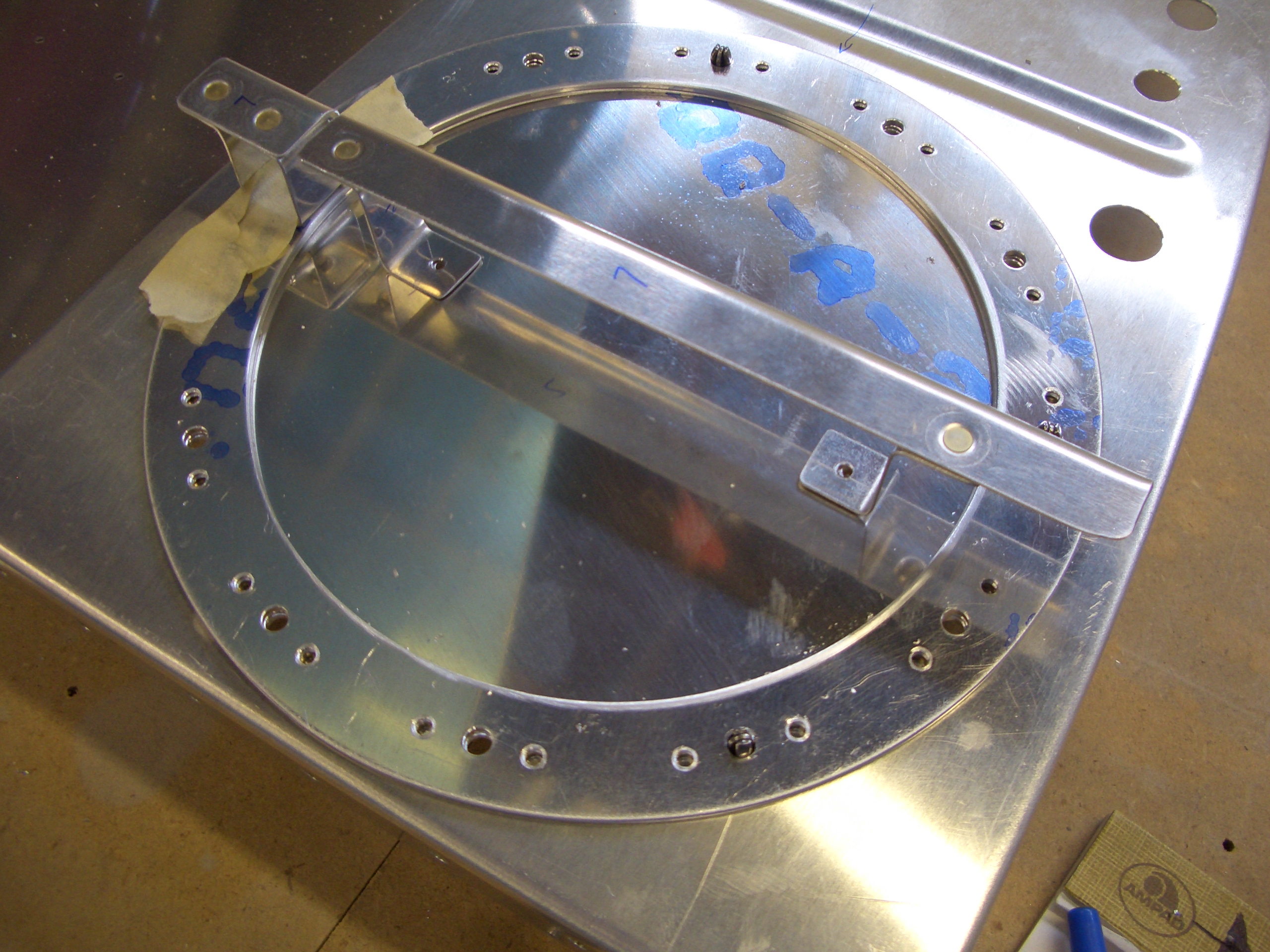
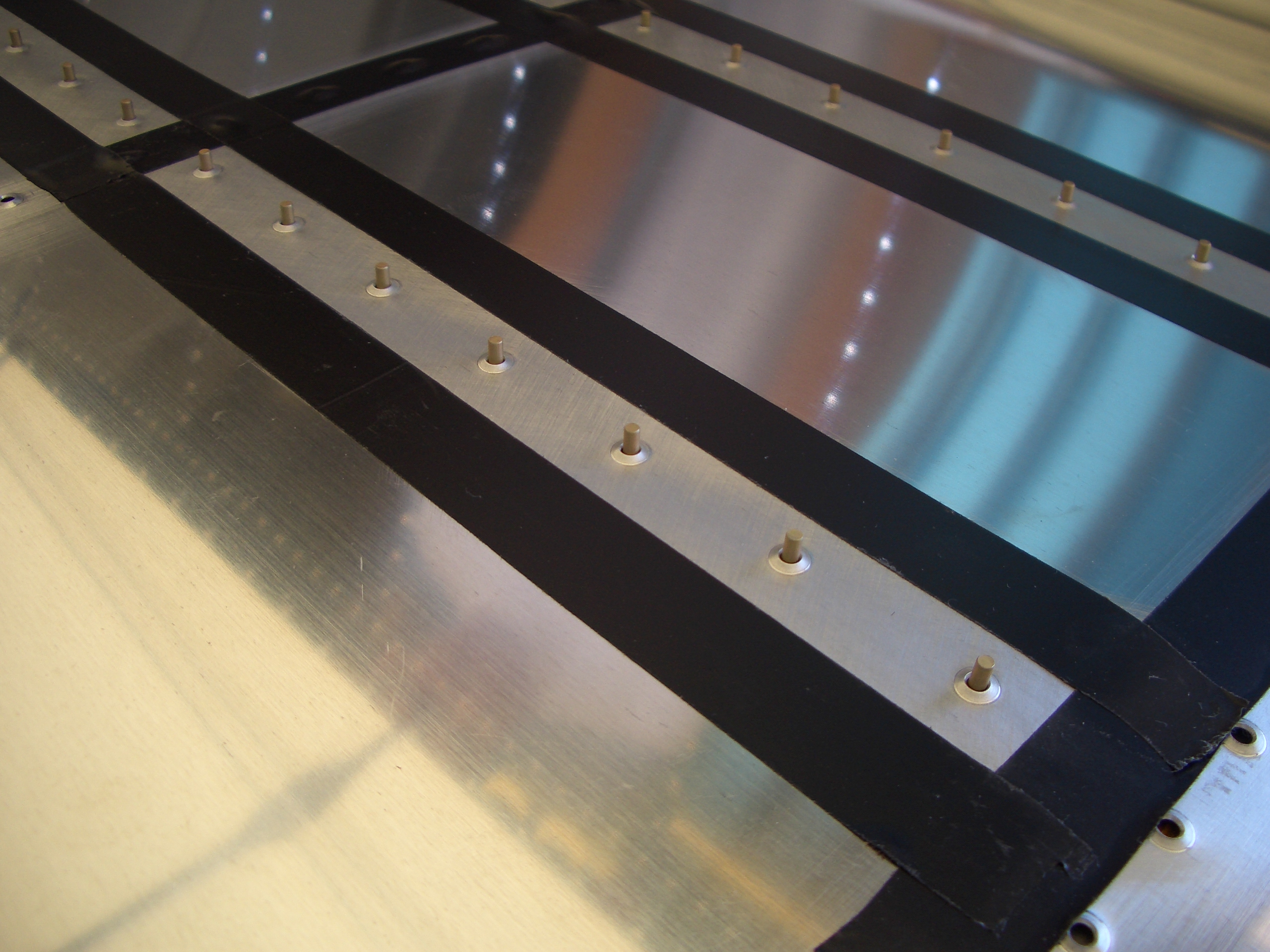
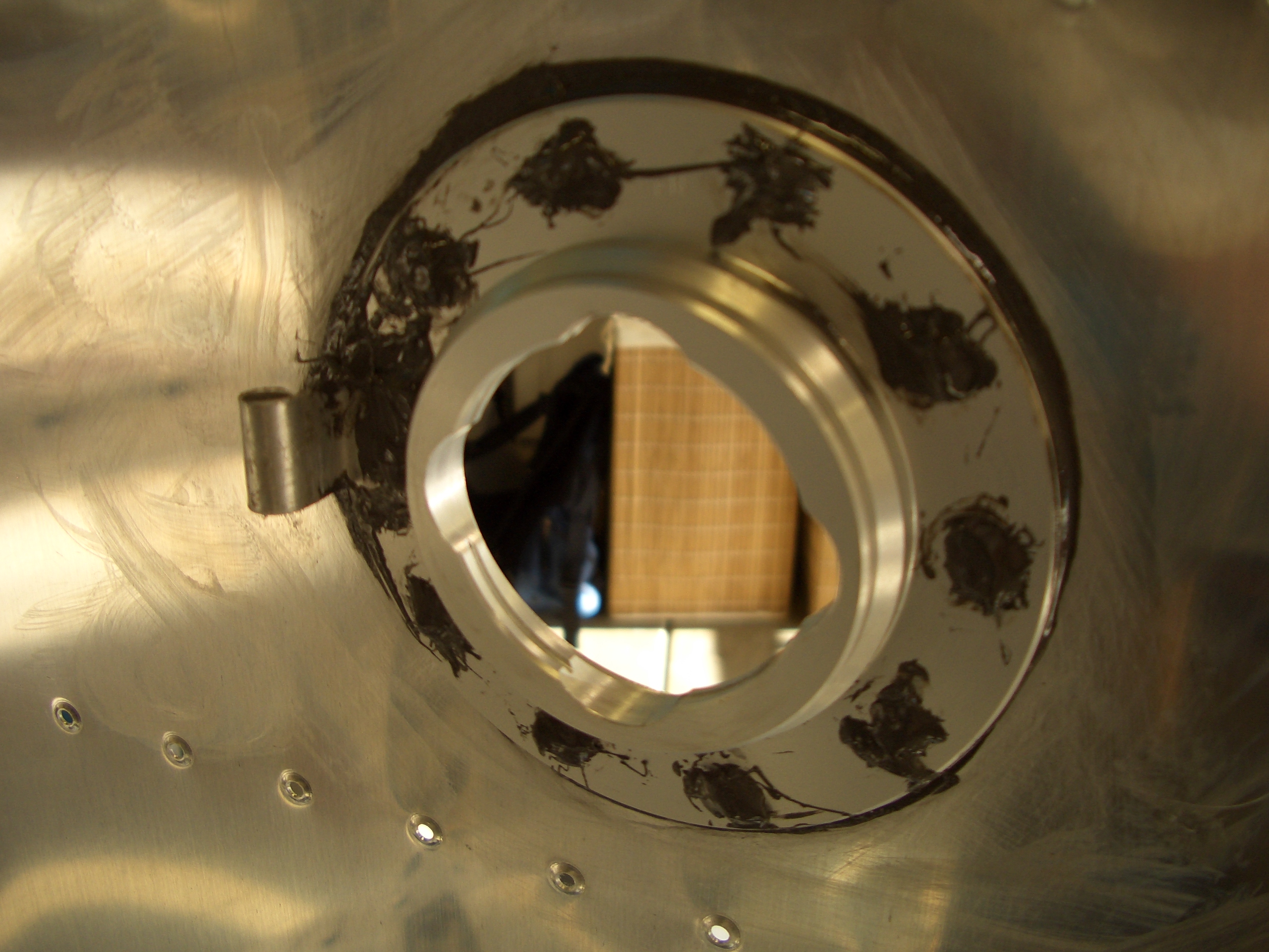
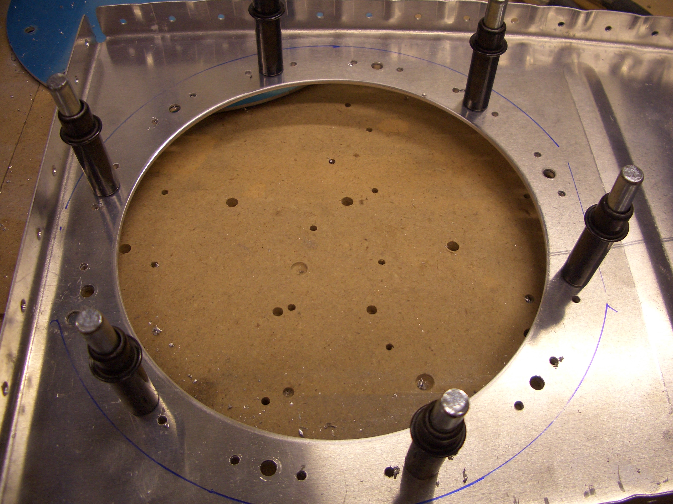
After the holes are drilled in the rib, the stiffener ring is clecoed to the rib…
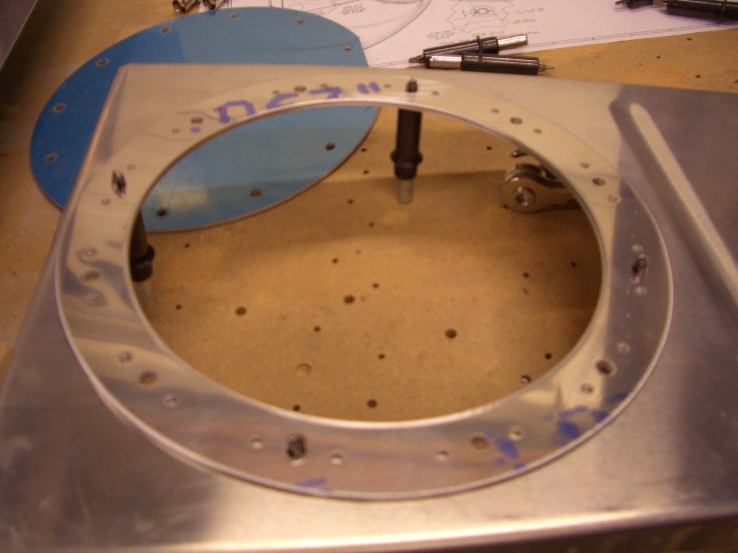
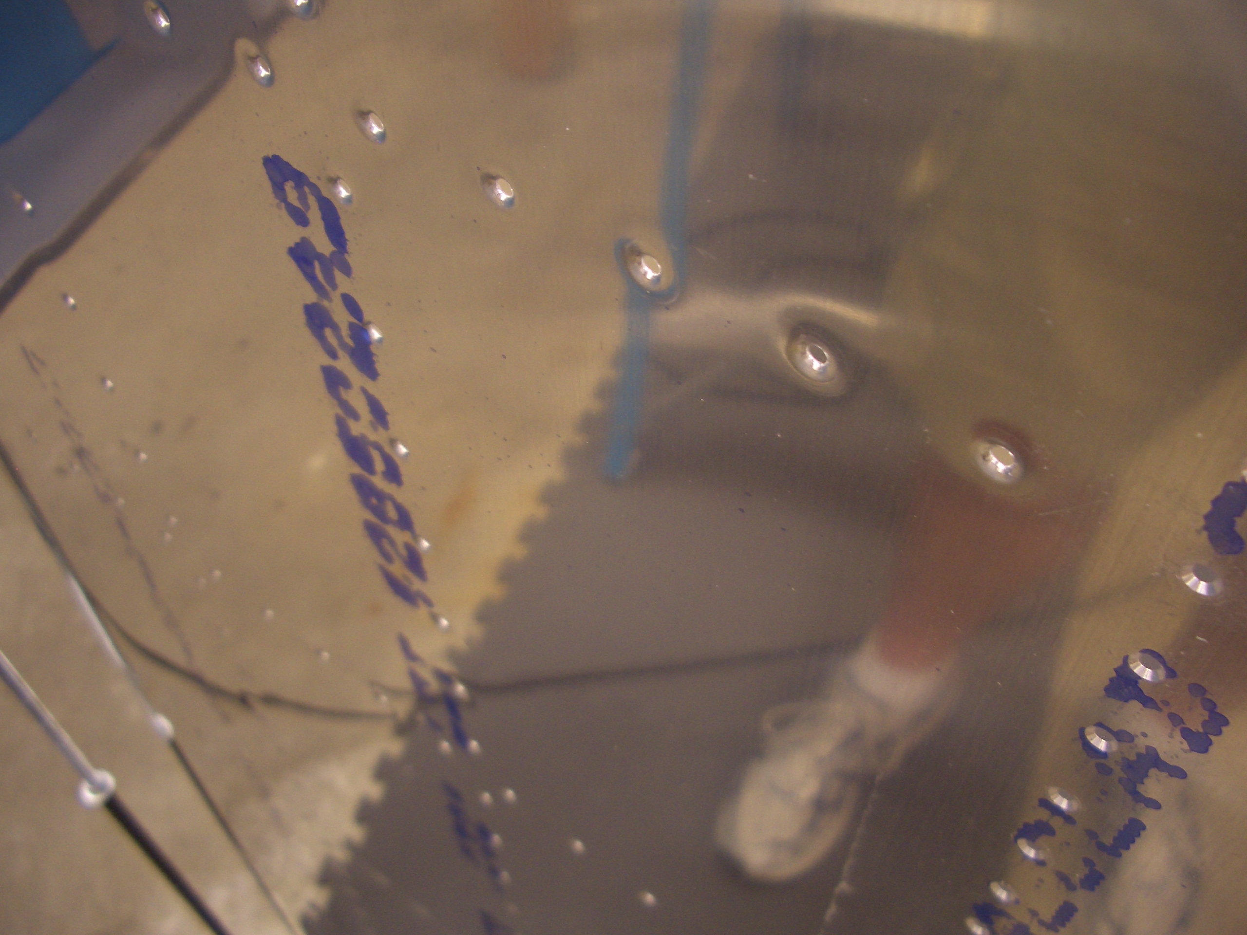
…and the nutplate rivet holes are all match drilled in the rib.
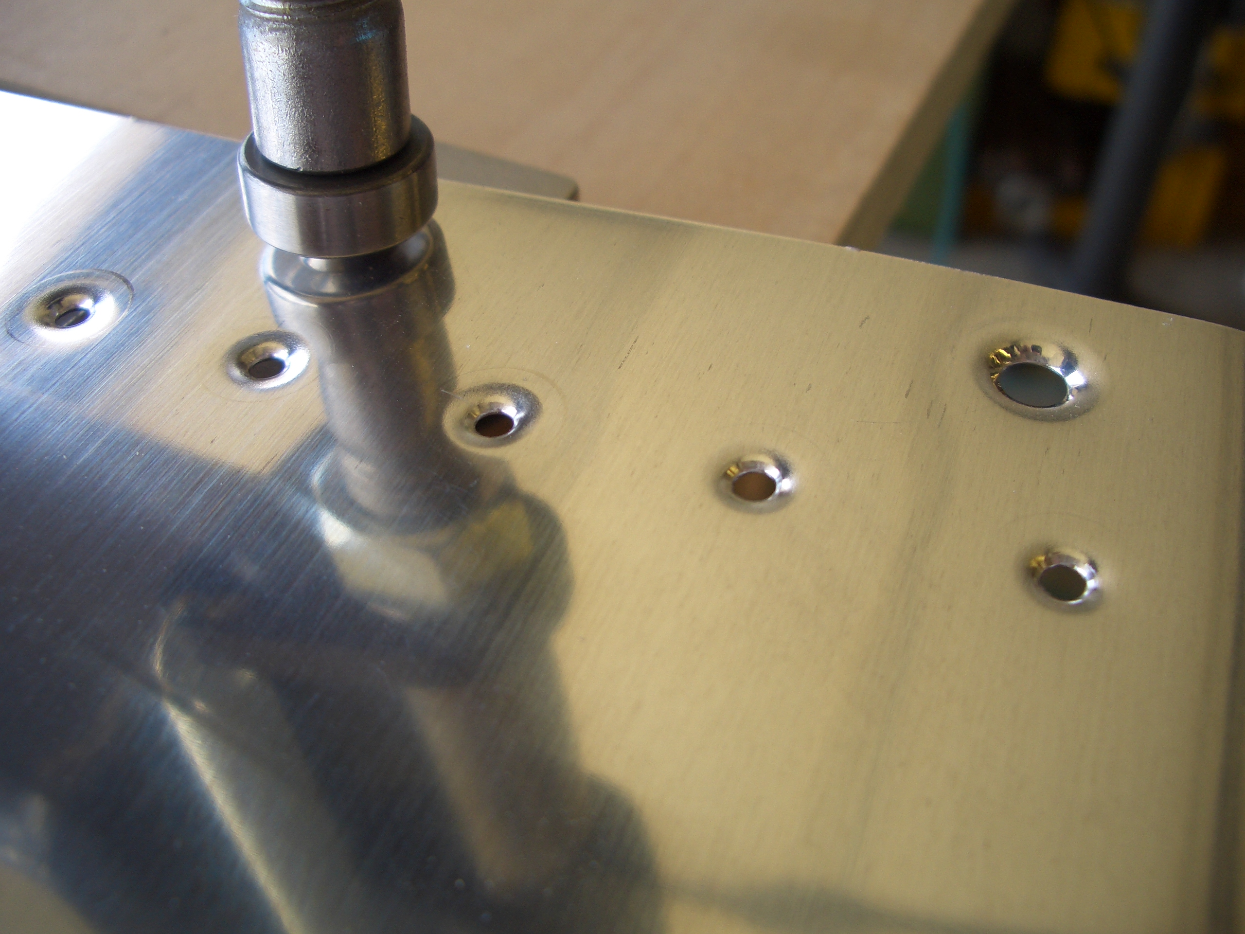
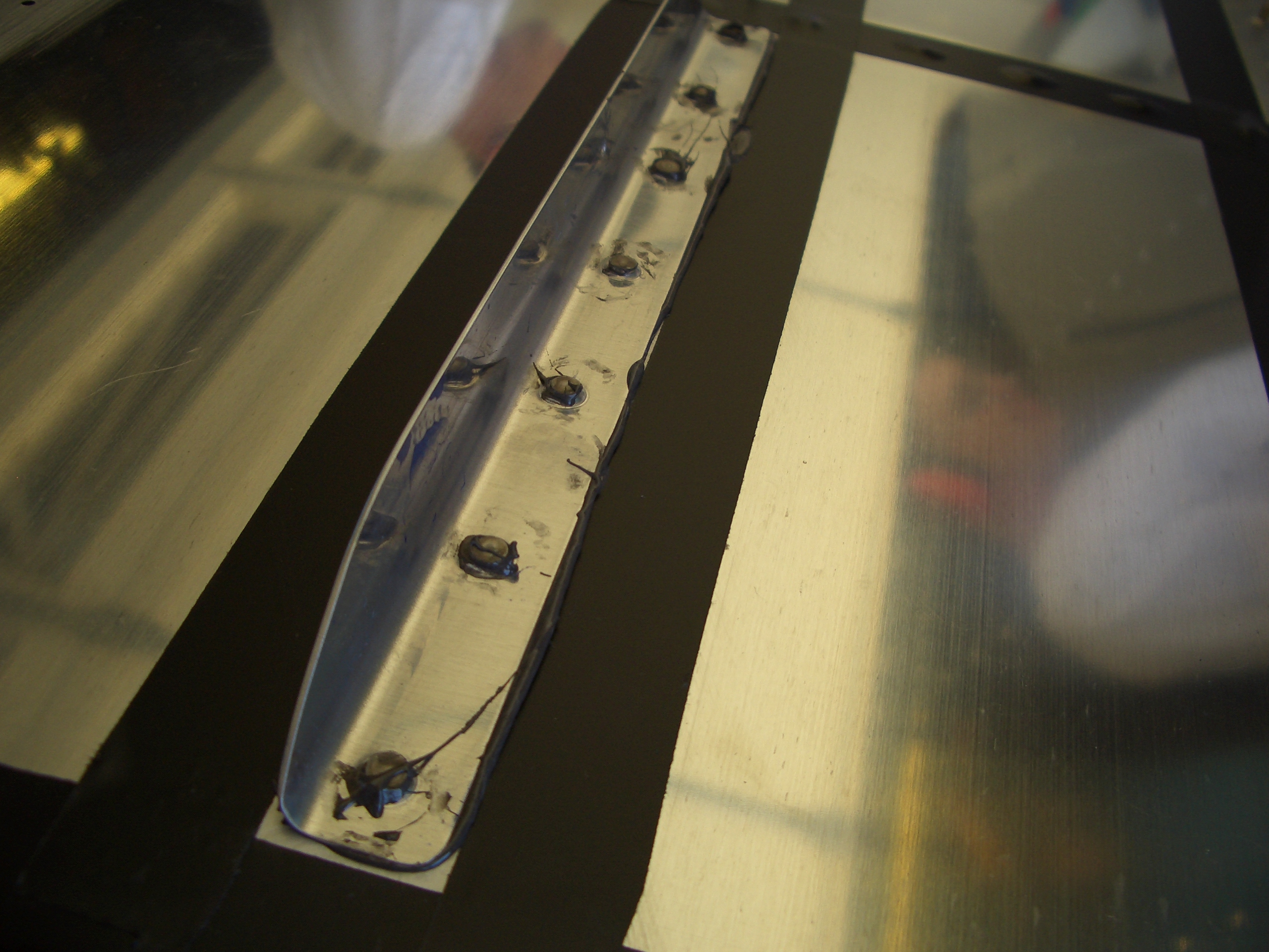
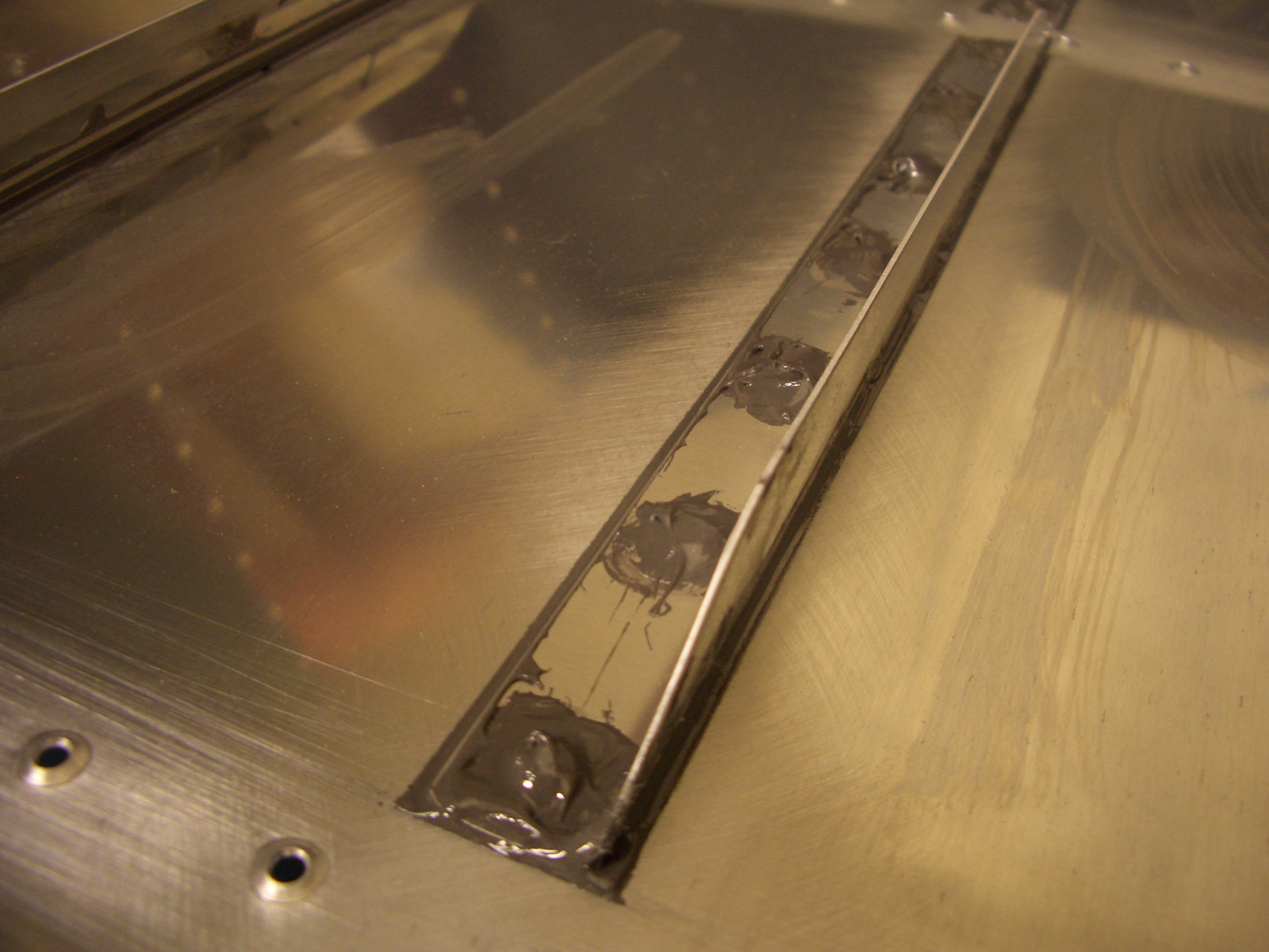
The rib is dimpled using the tank dies for the rivets that will hold the stiffener ring and nutplates in place.
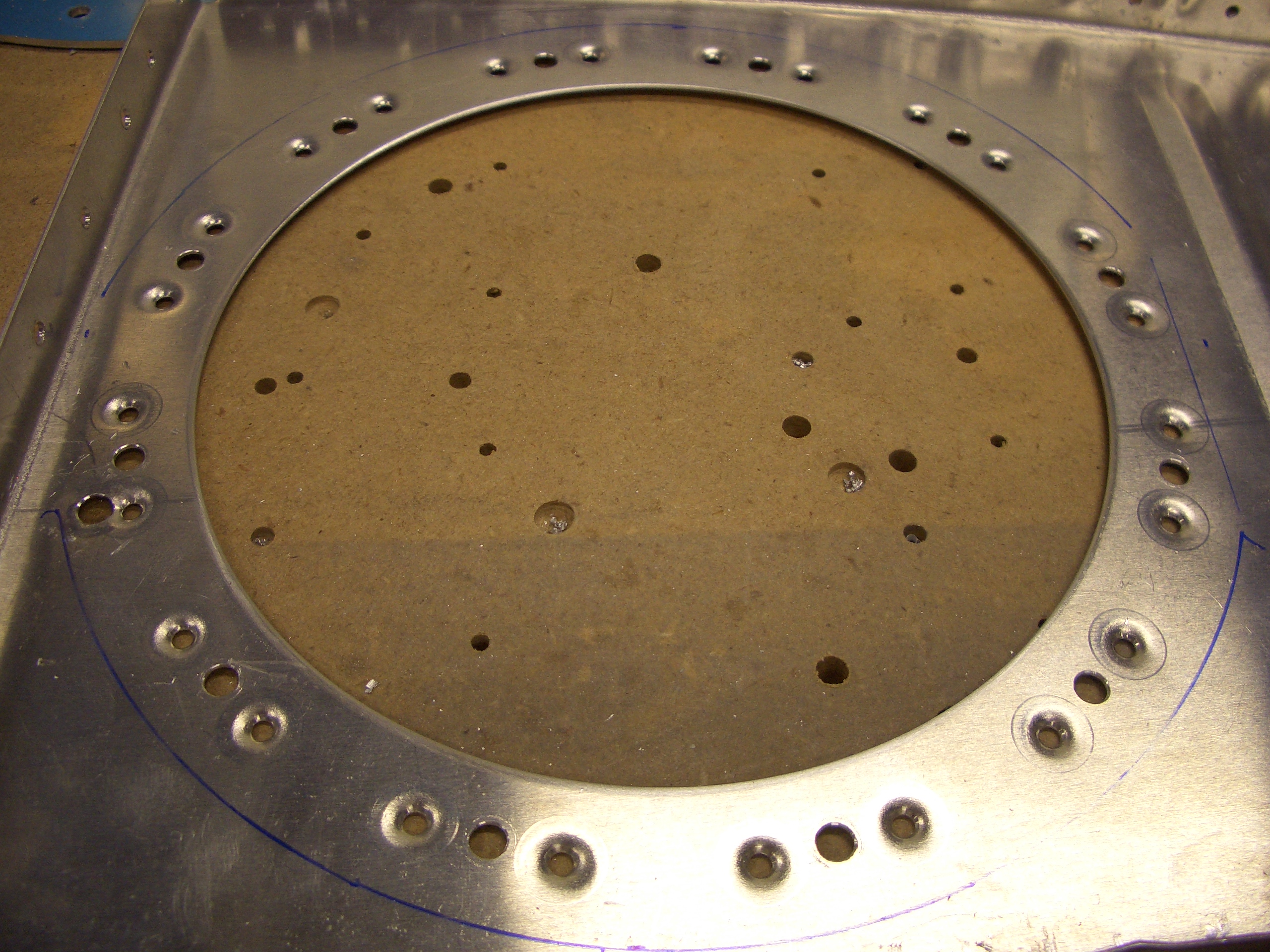
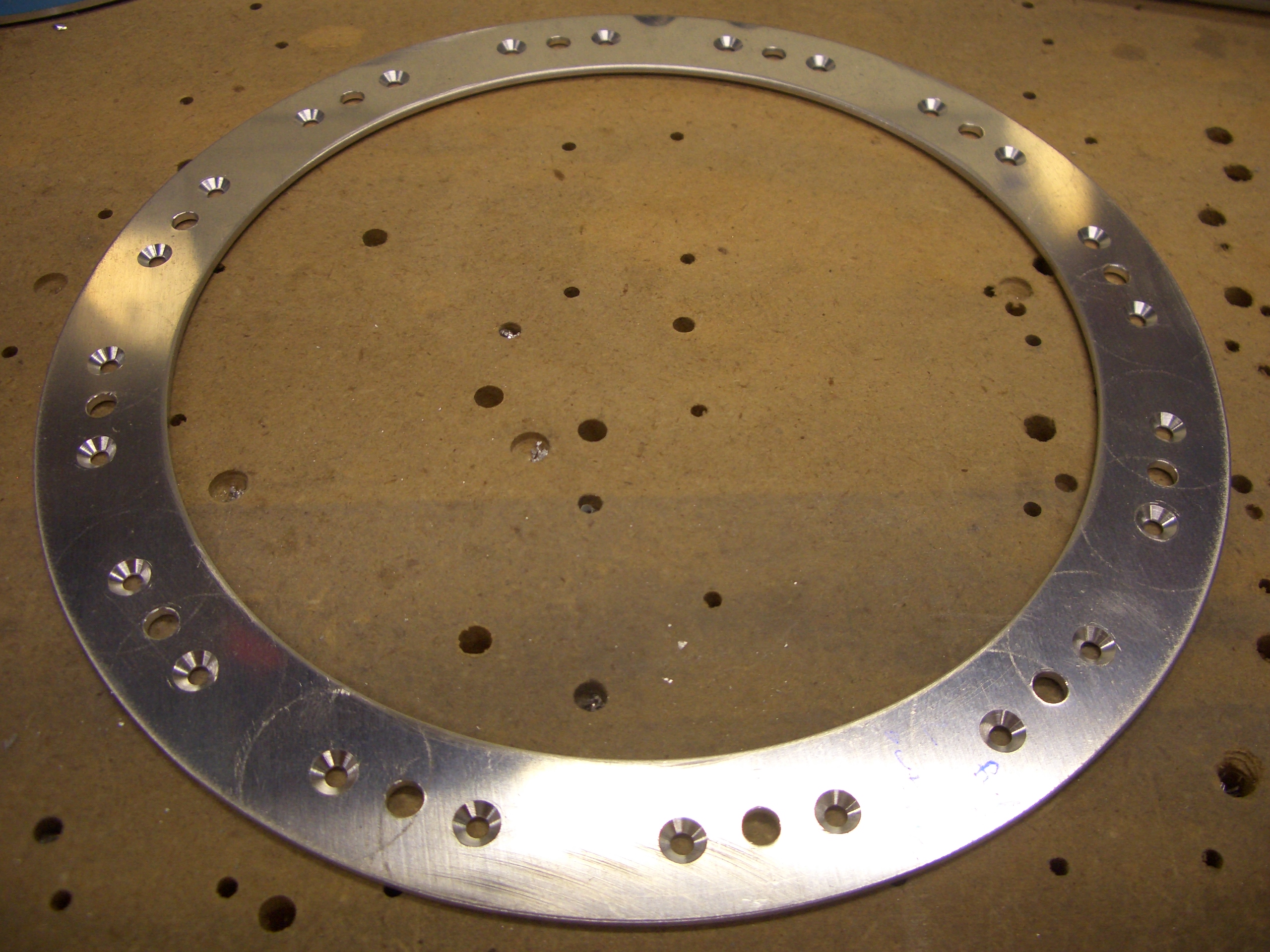
The stiffener ring is countersunk for the dimples in the rib. These will be set aside and riveted later when I start sealing the tank.