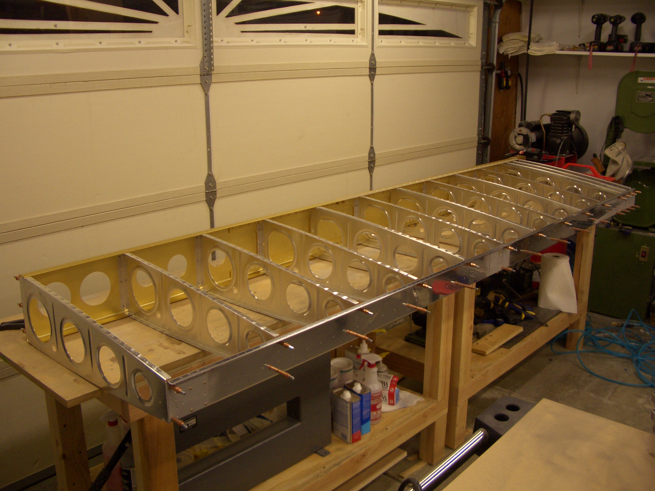
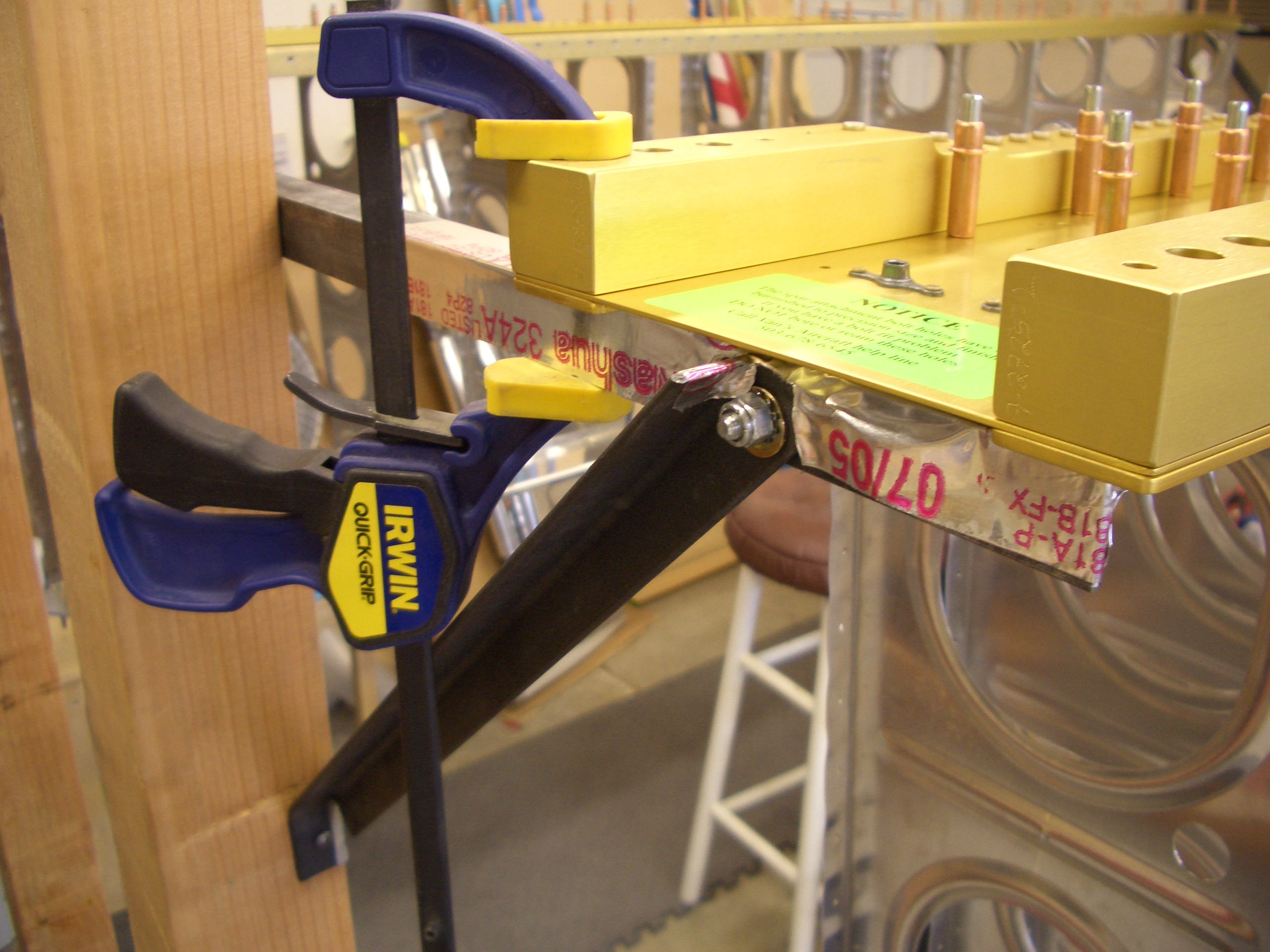
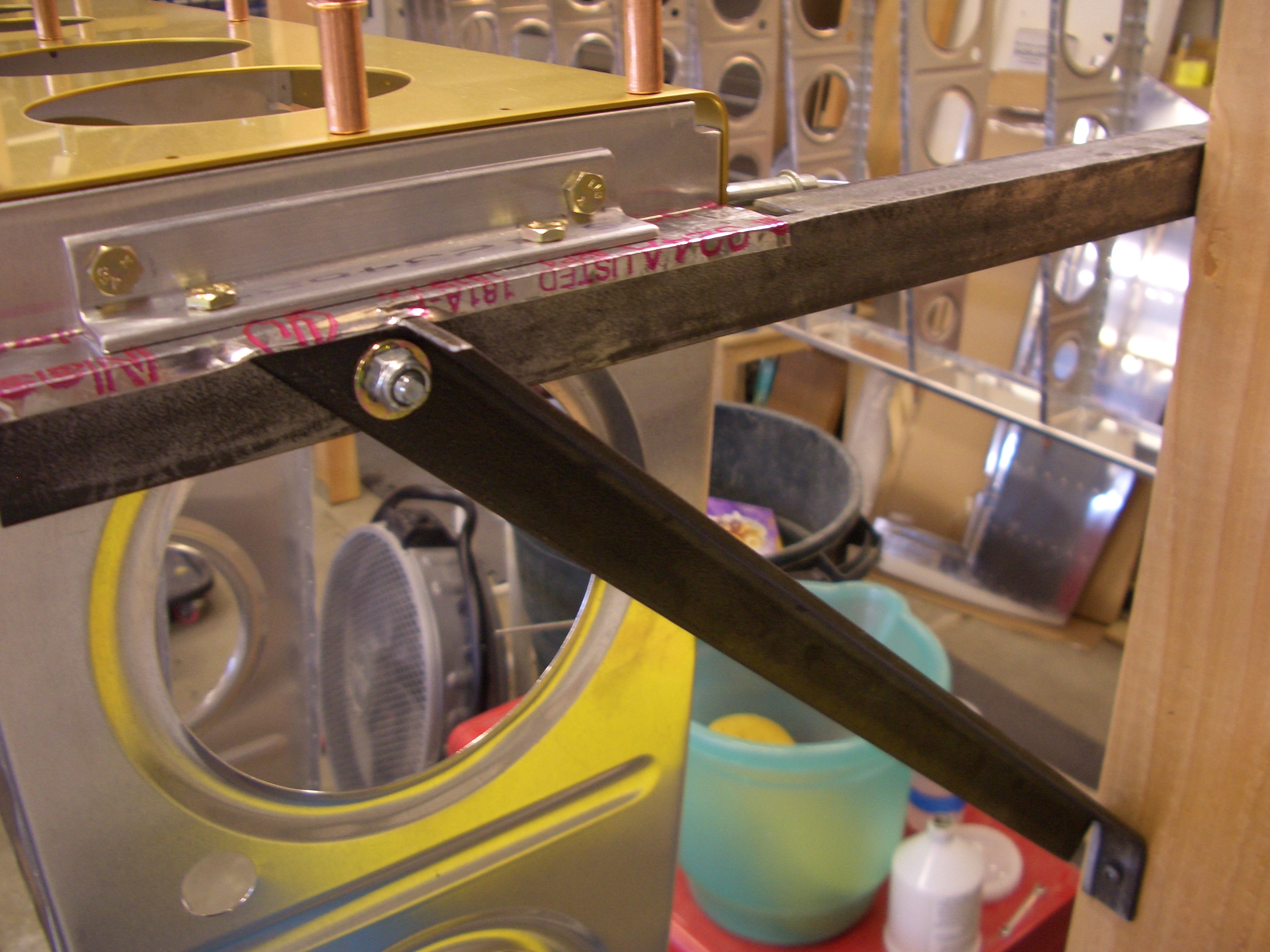
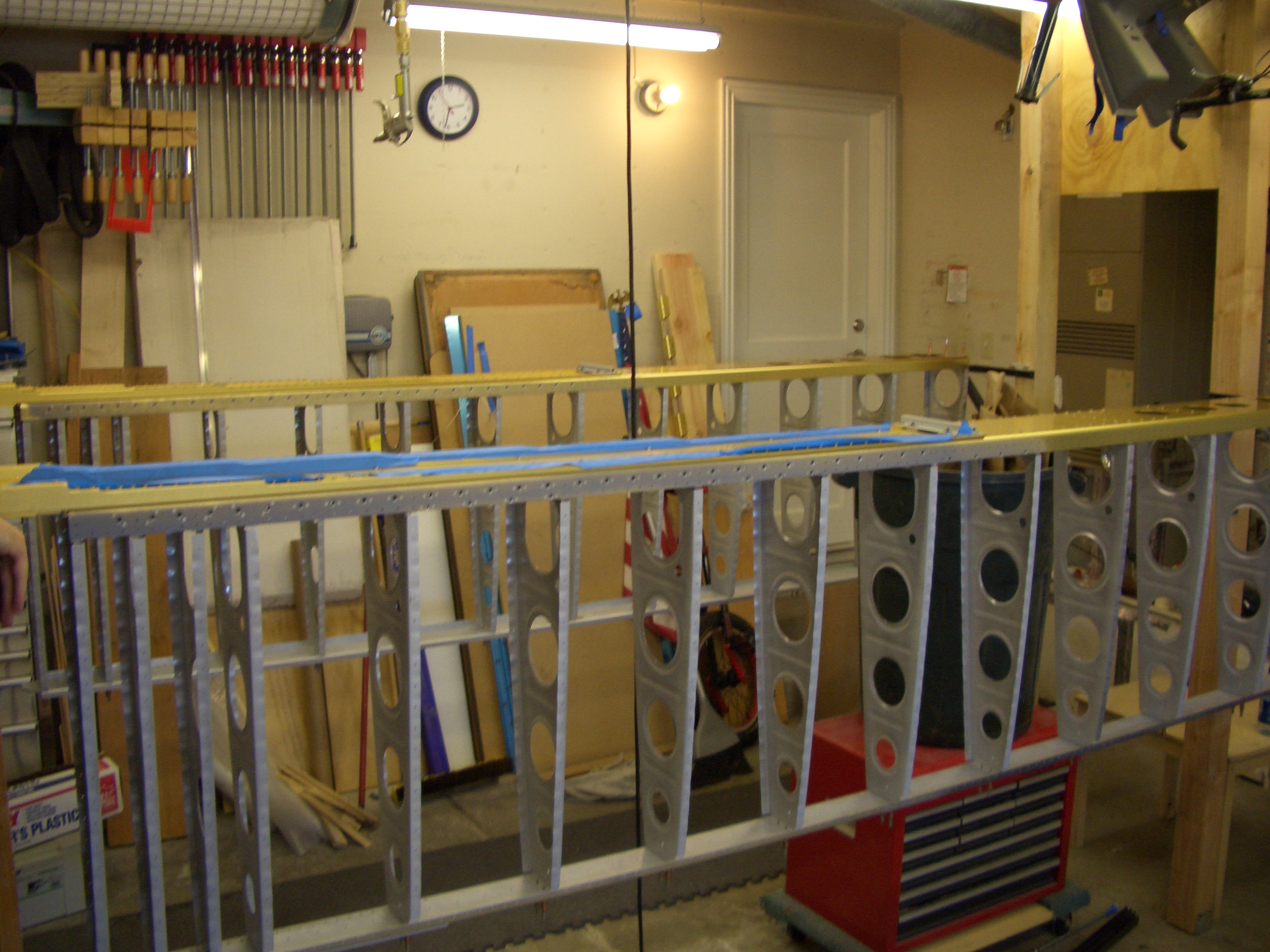
The weight of the wing causes the middle to sag a bit, so I put a support near the middle of the rib. This is basically just a piece of steel tubing and some allthread with a washer and nut. I put a couple of plastic feet on each end to prevent scratching the spar and to prevent it from slipping on the floor.
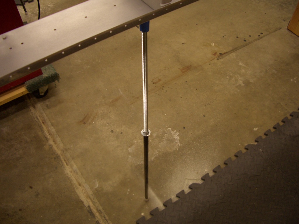
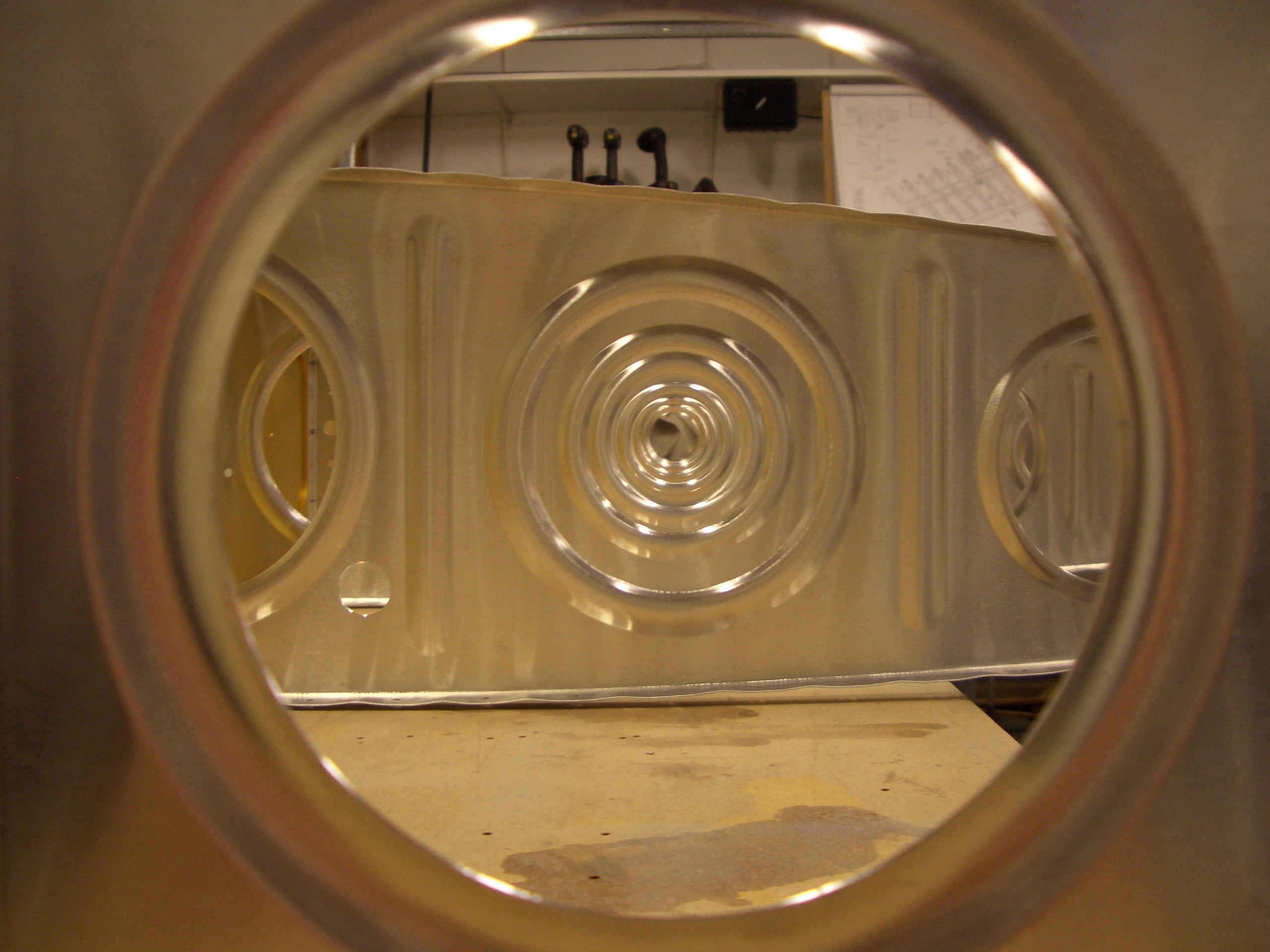
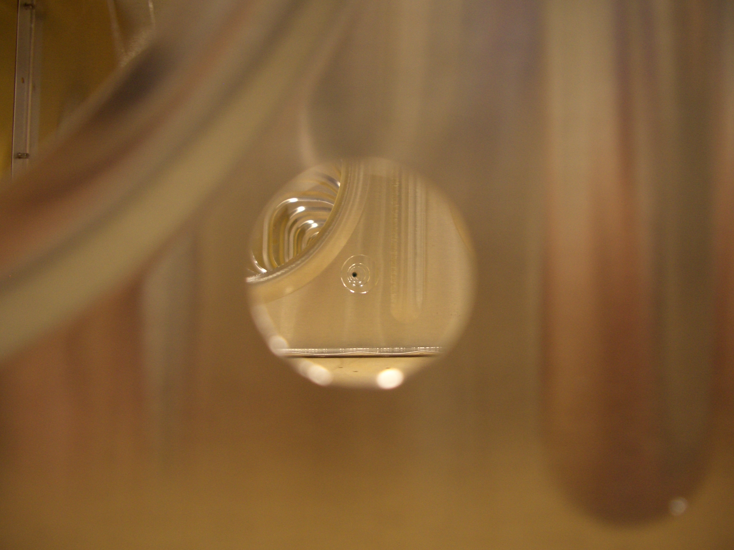
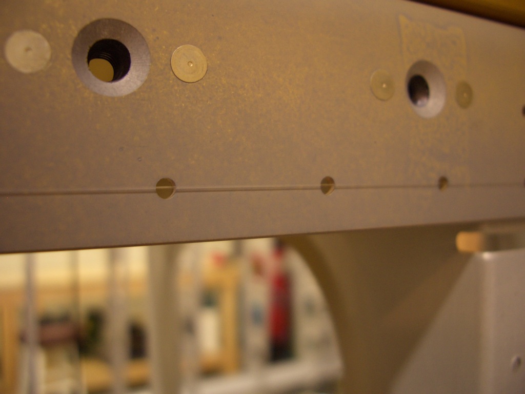
I stretched a piece of fishing line across the lower set of holes in the spar and adjusted the support until the fishing line ran through the center of all of them.
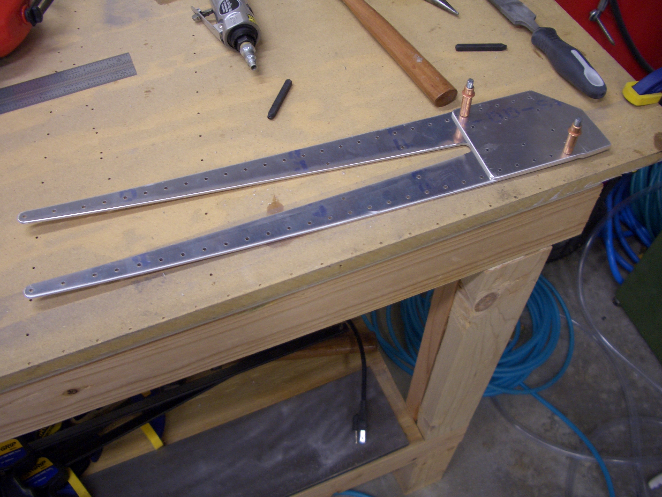
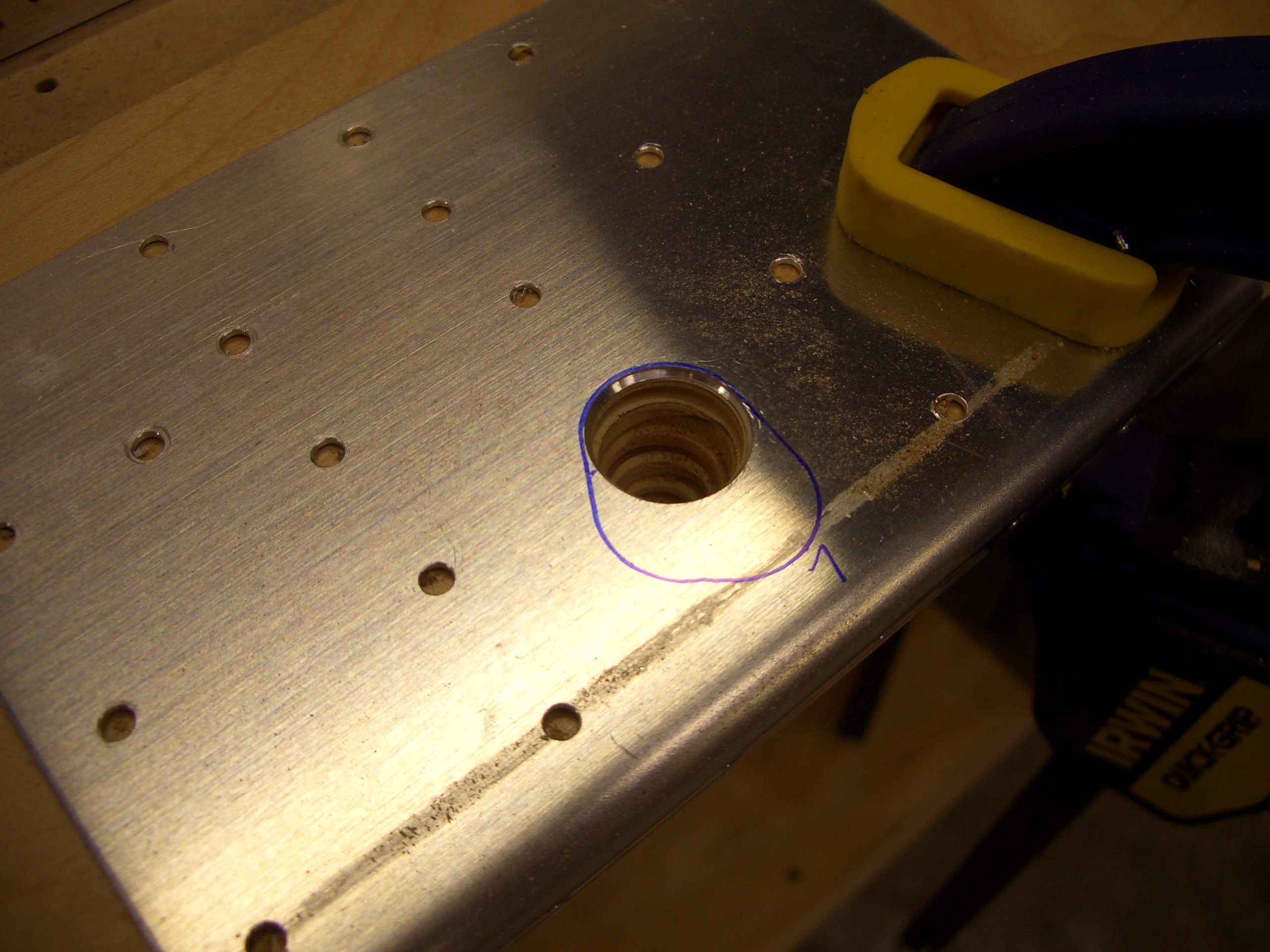
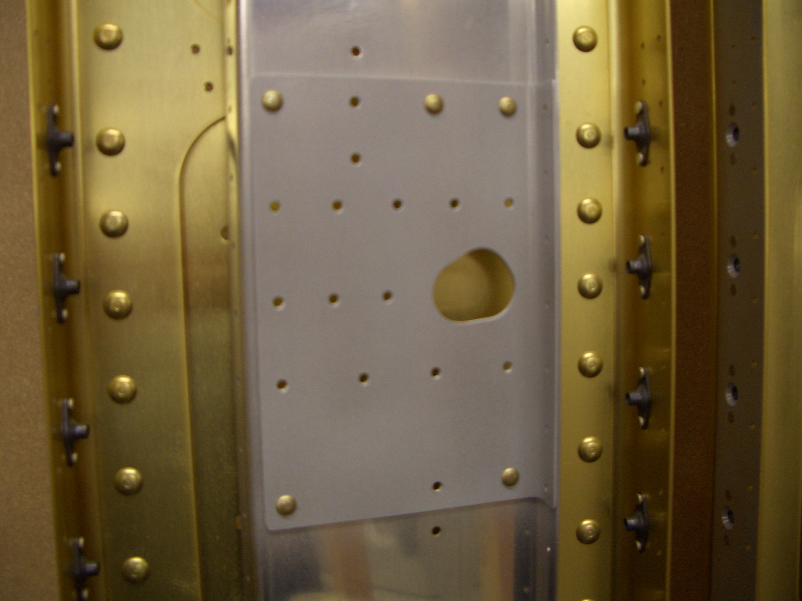
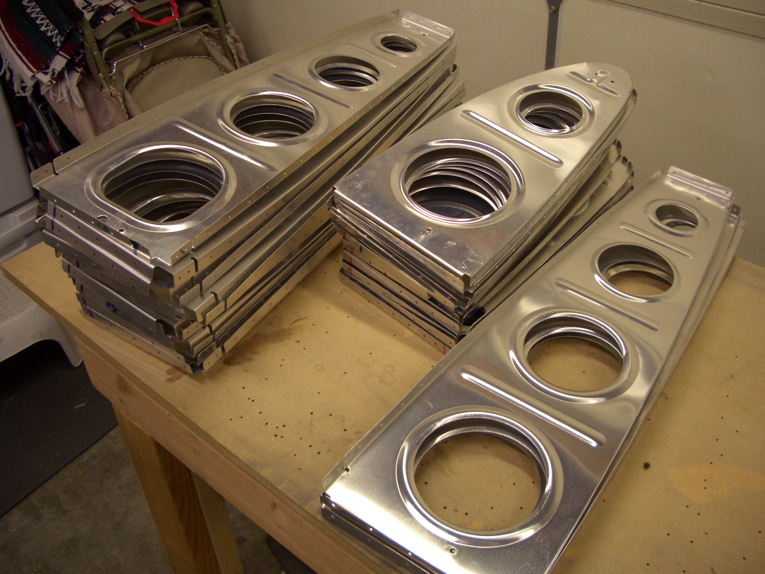
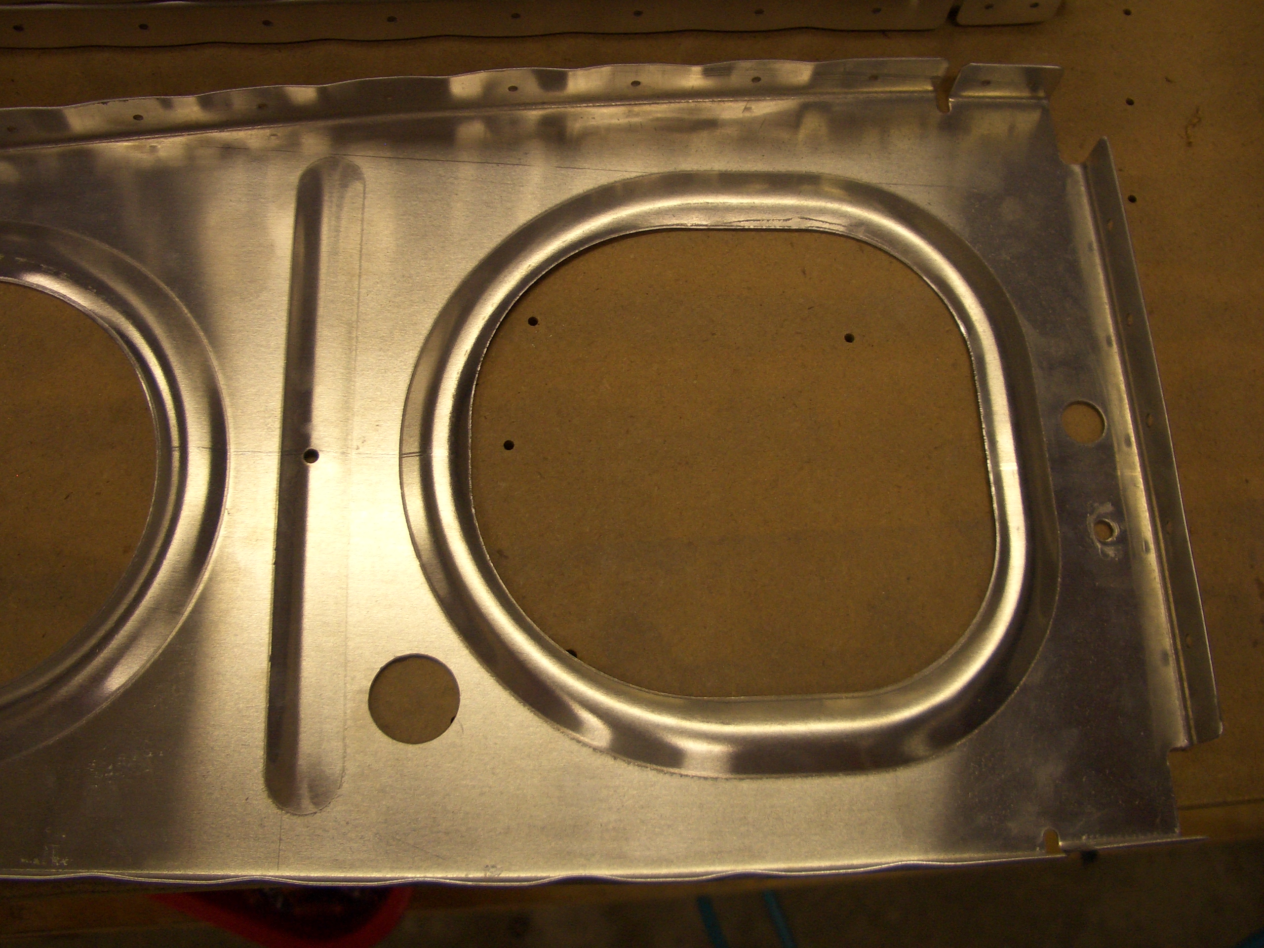
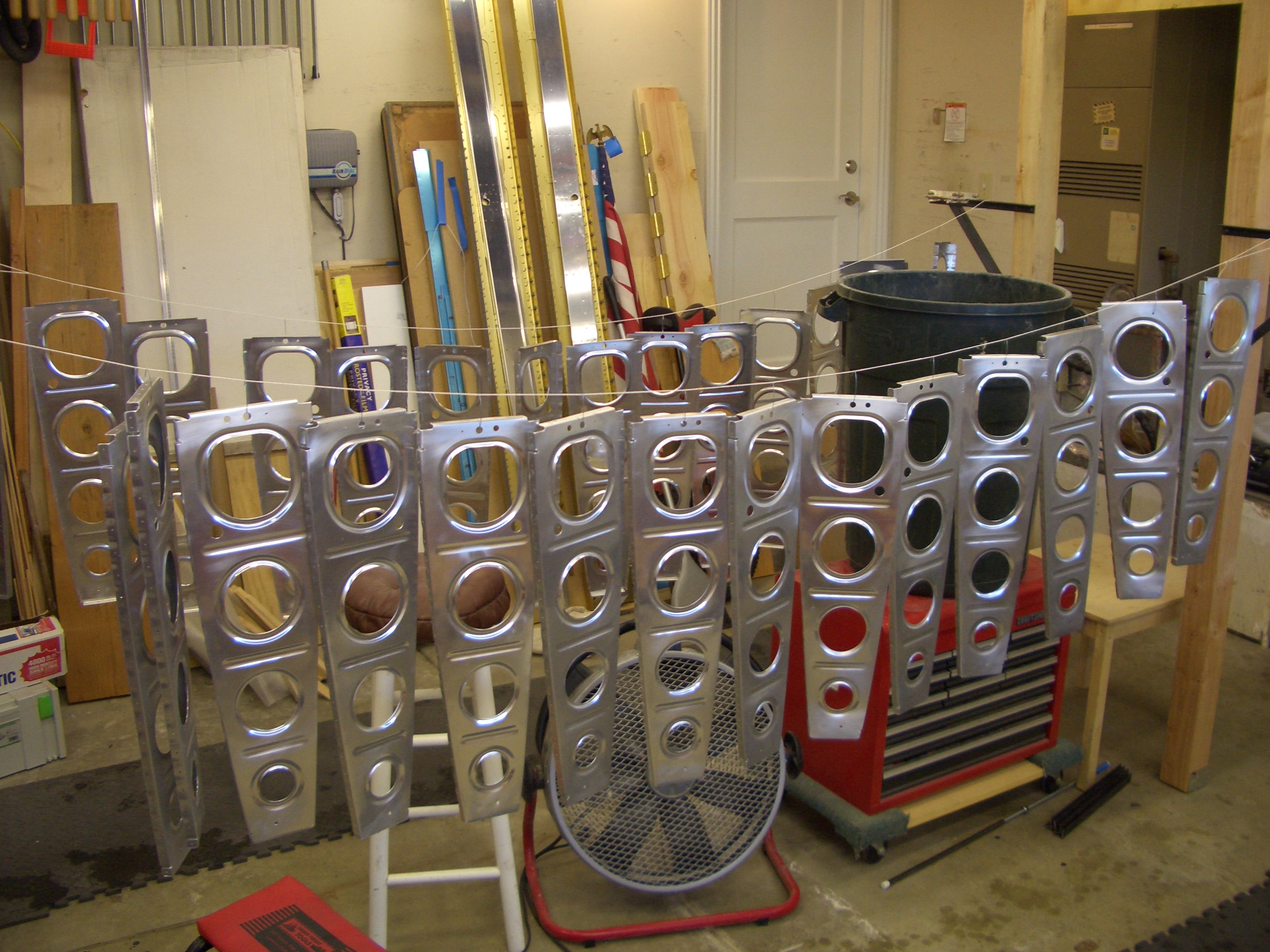
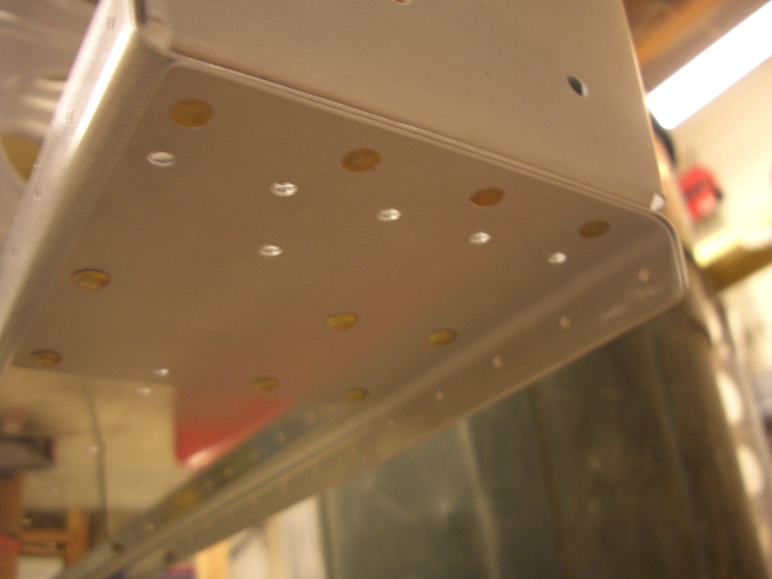
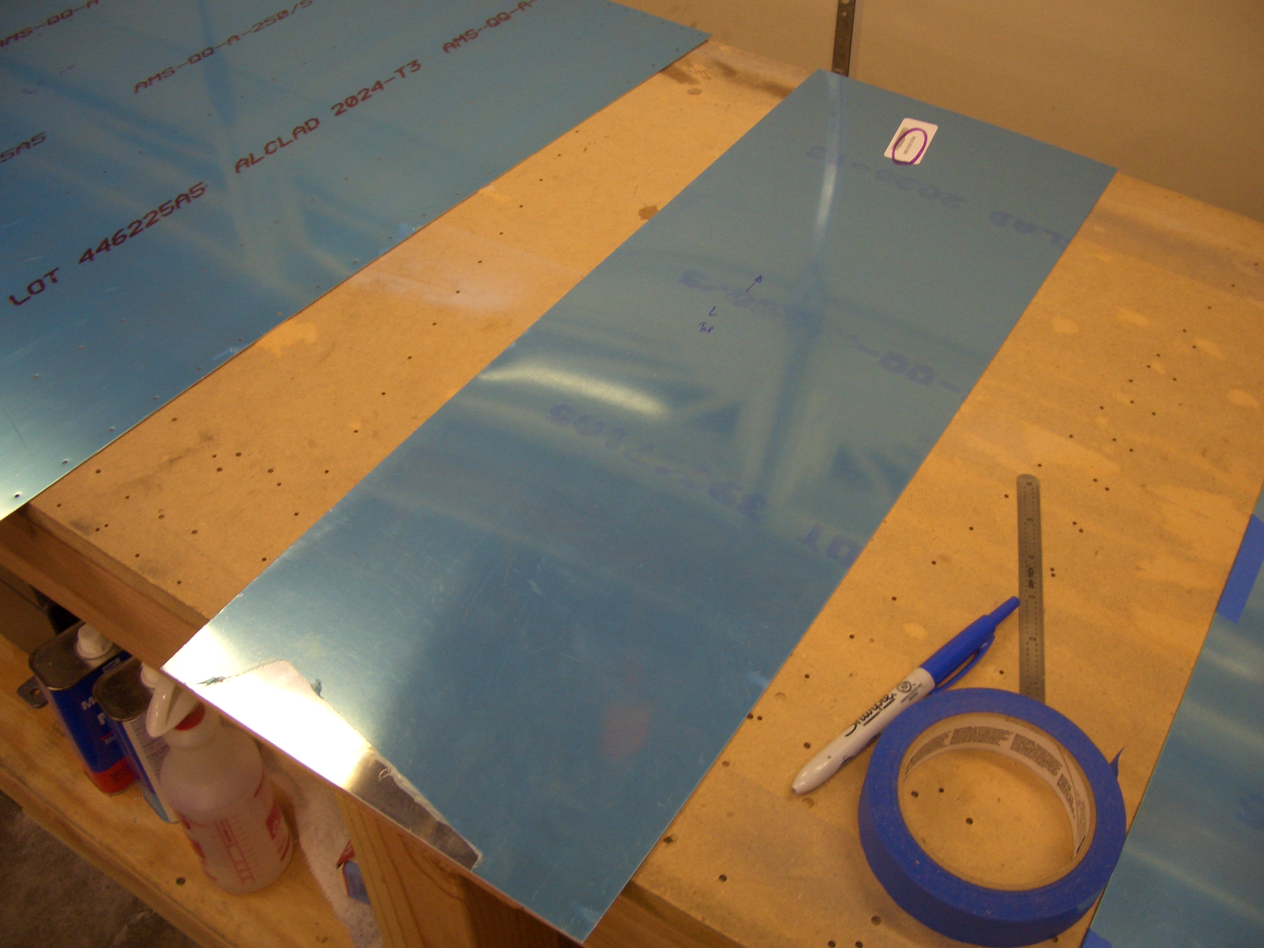
The wing walk doublers have to be cut from a larger piece of aluminum sheet.
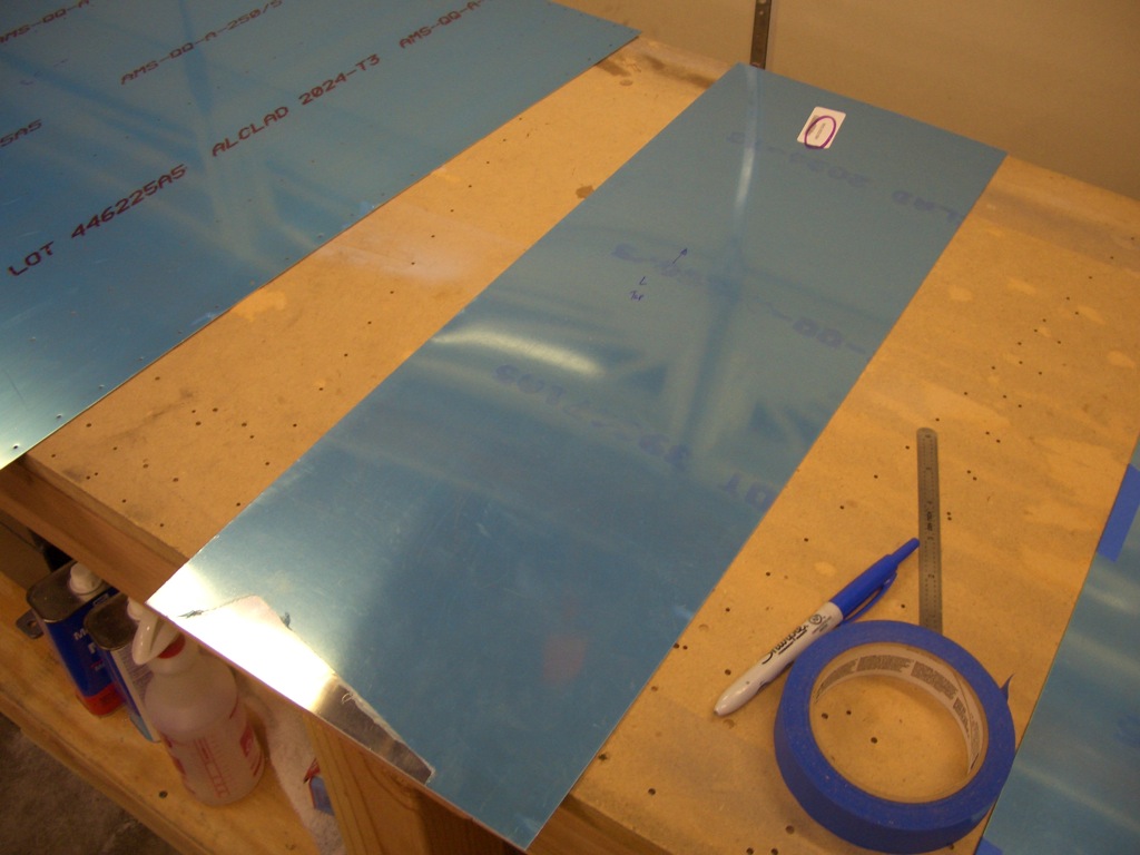
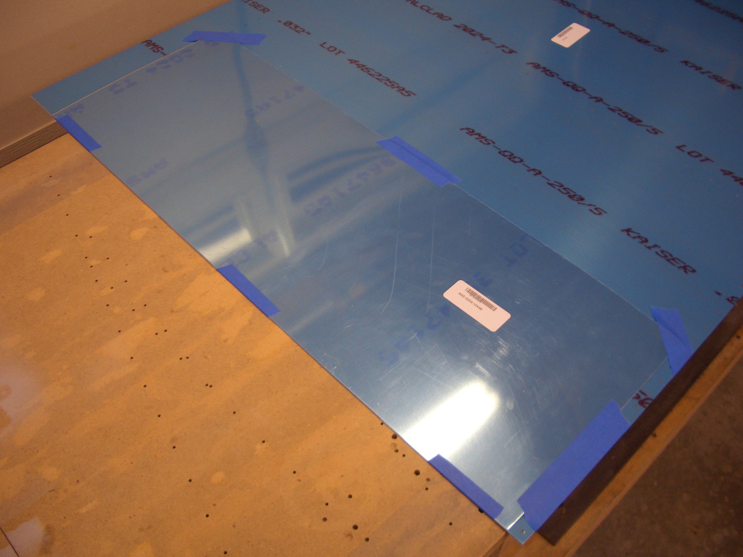
Then positioned under the top wing skin for match drilling.

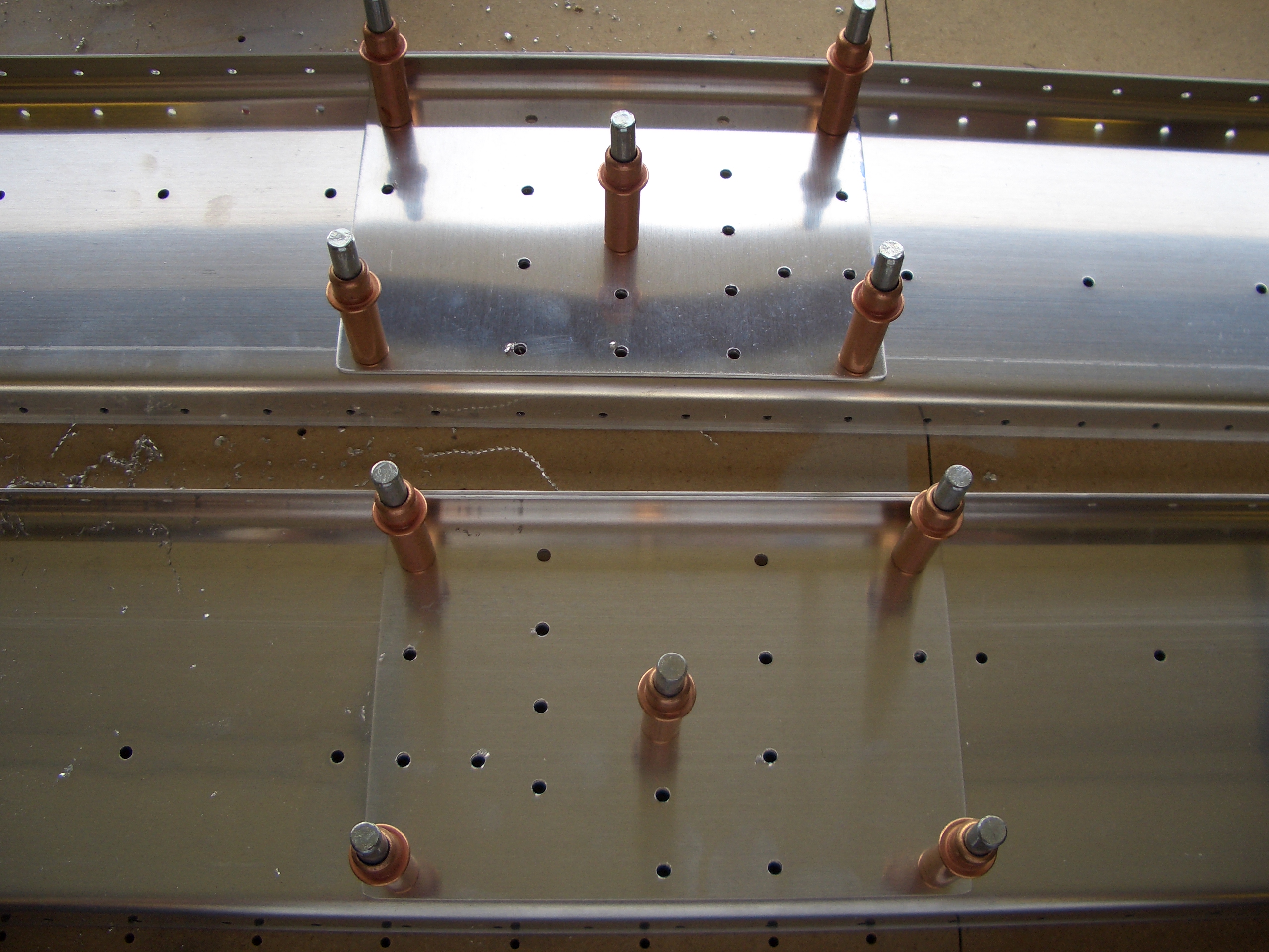
Here are both doublers match drilled to the top skins.
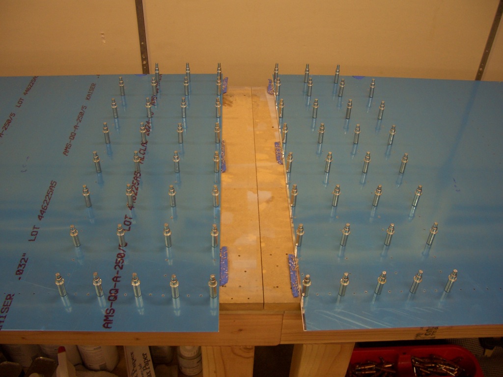
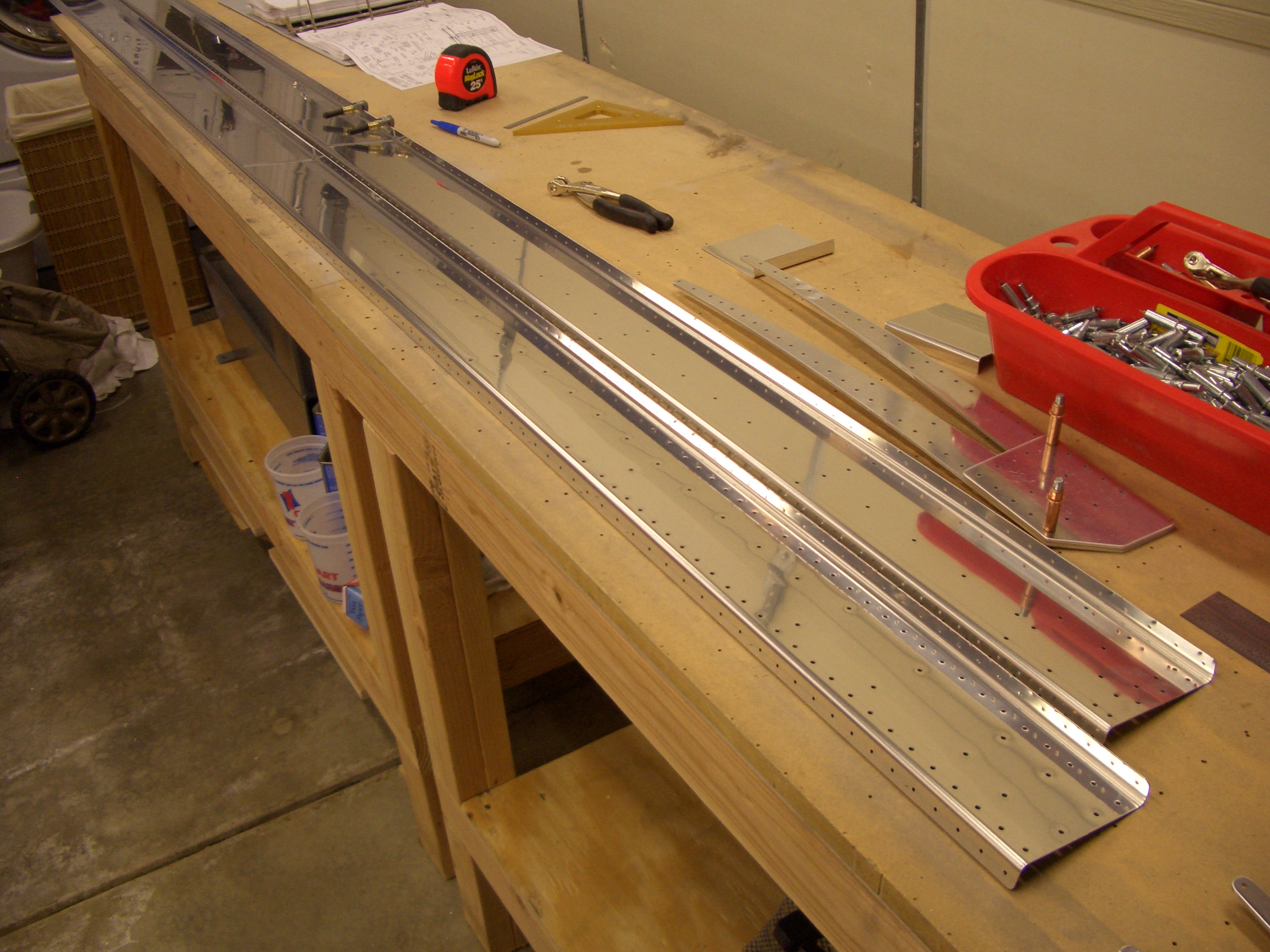
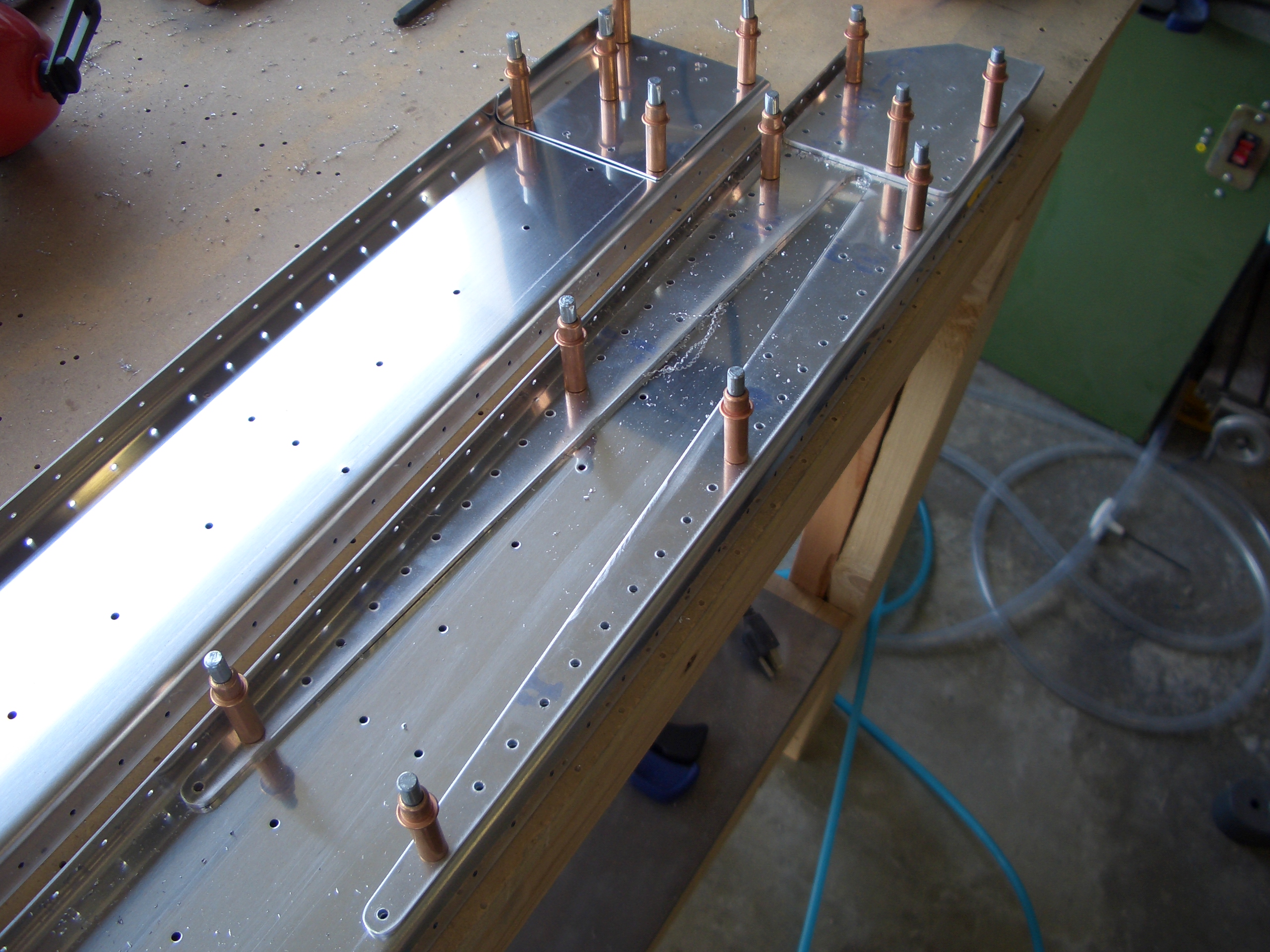
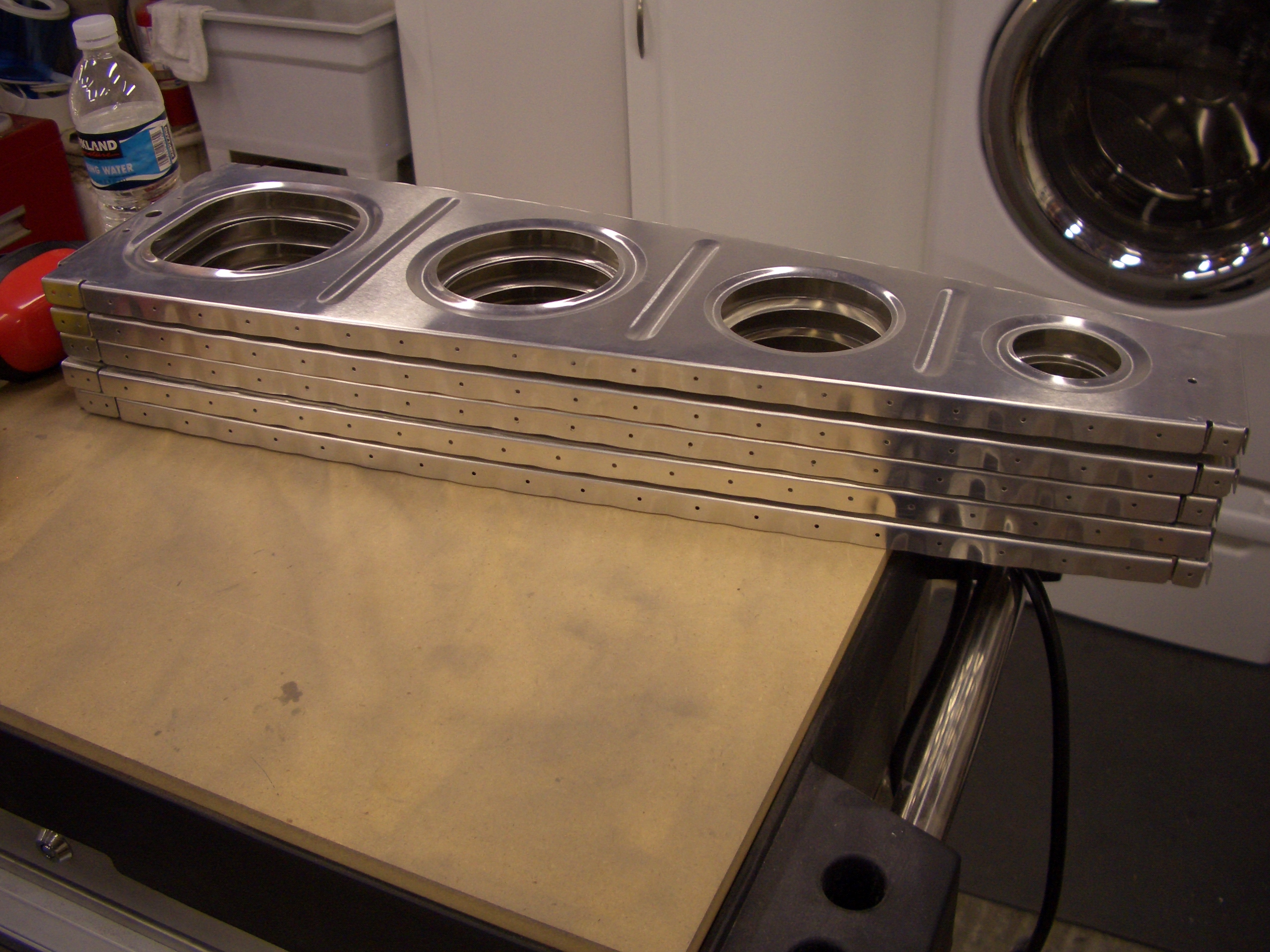
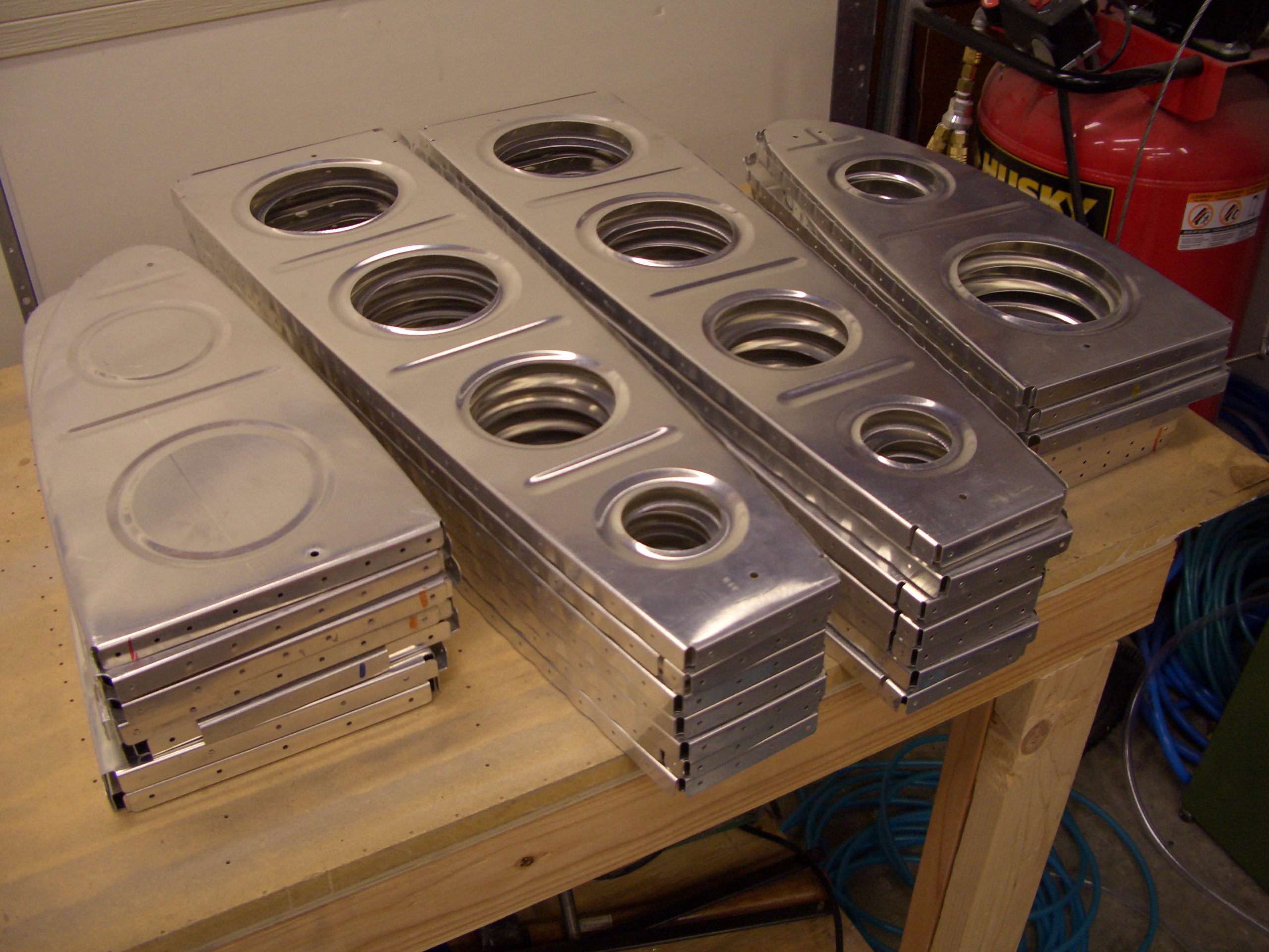
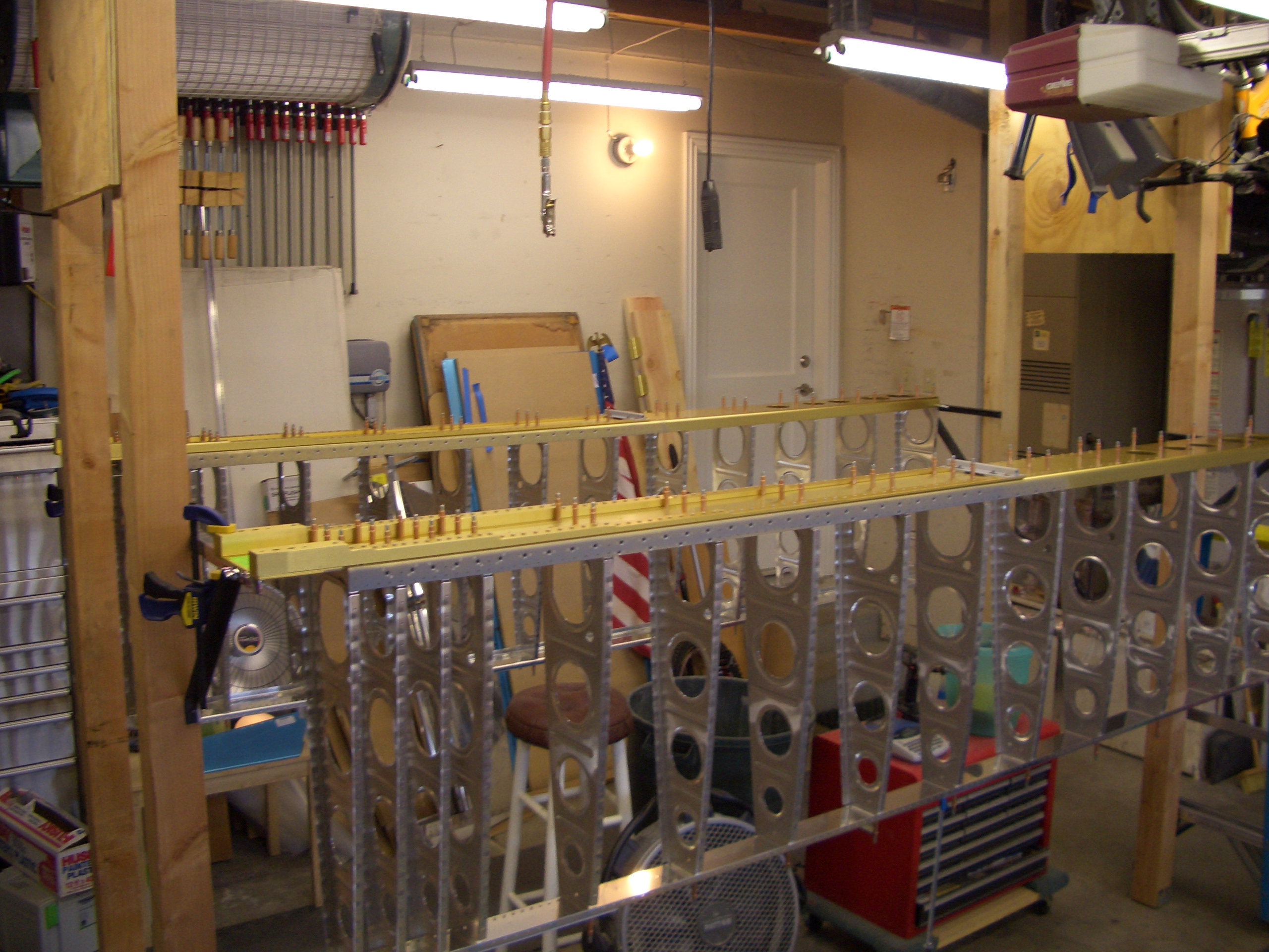
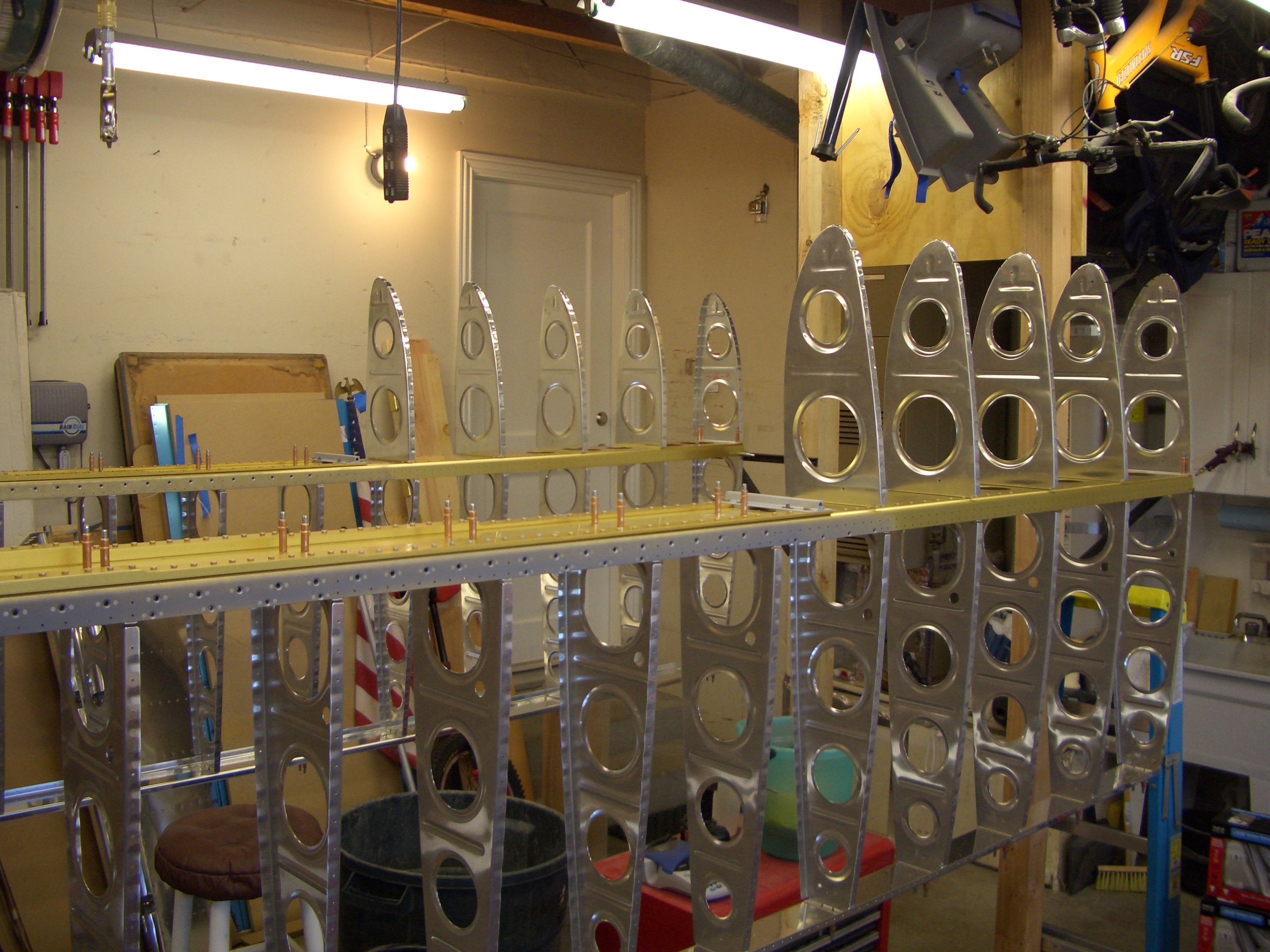
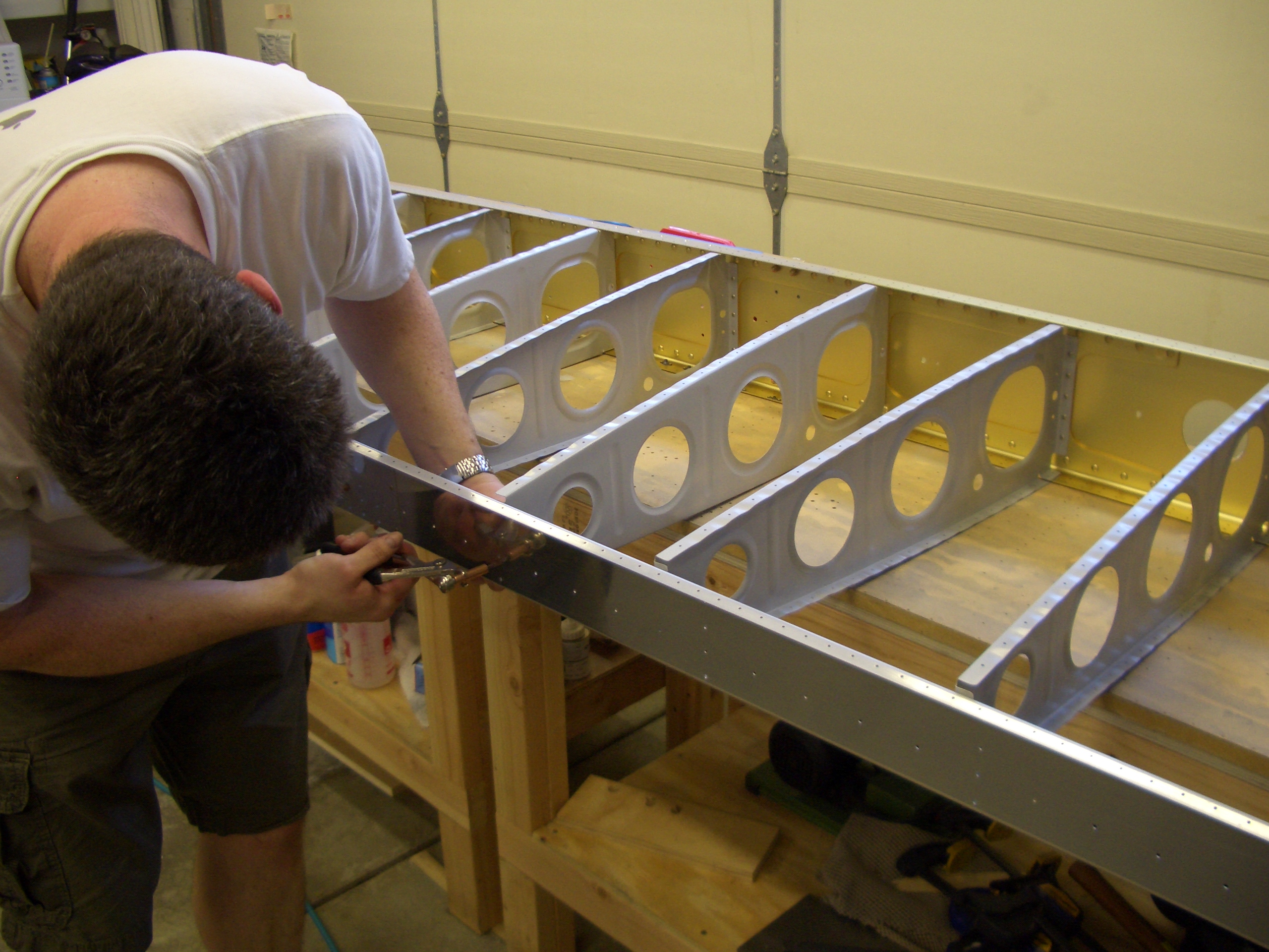
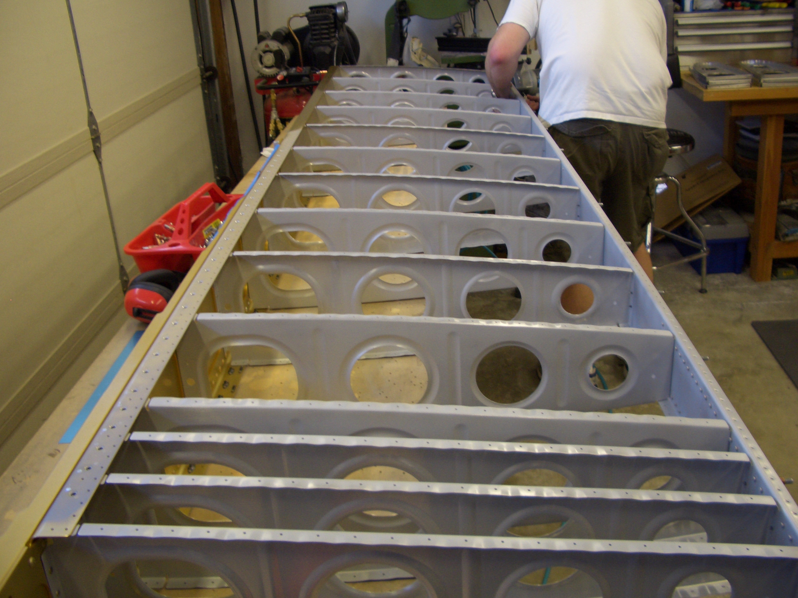
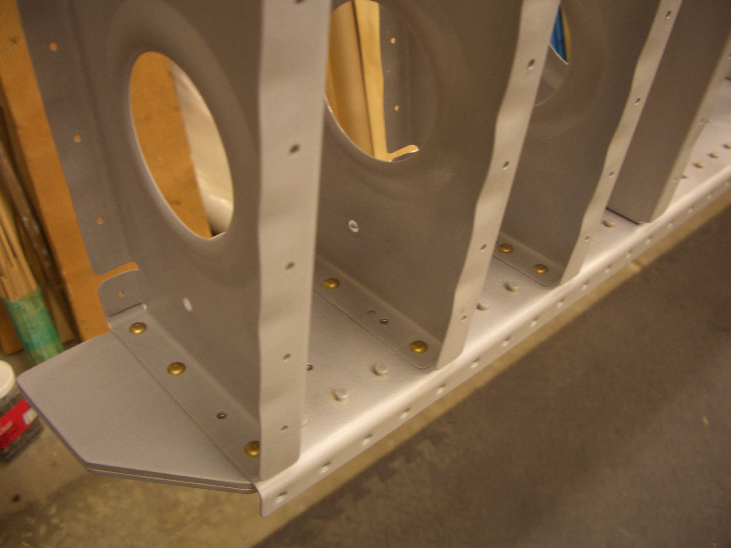
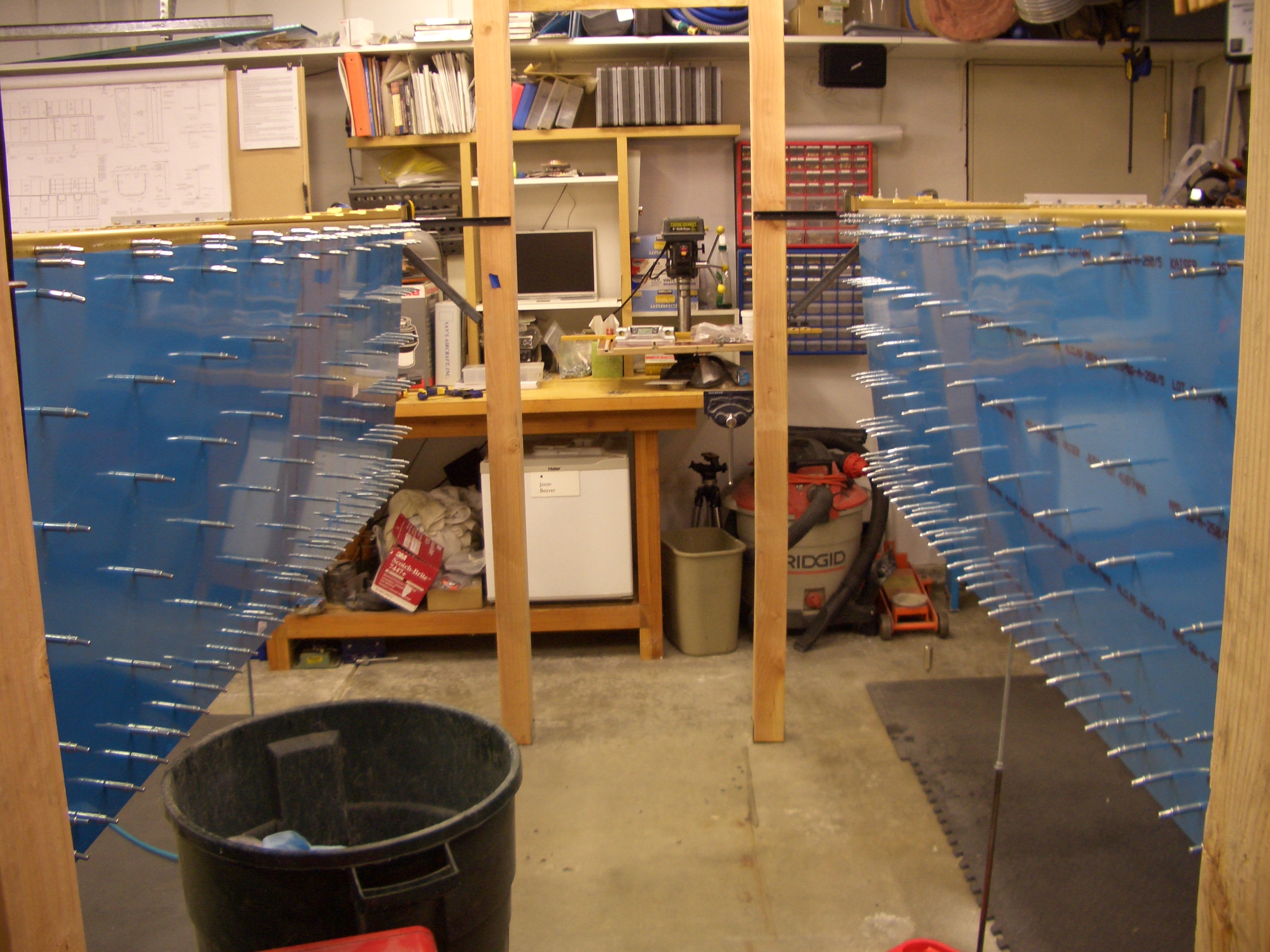
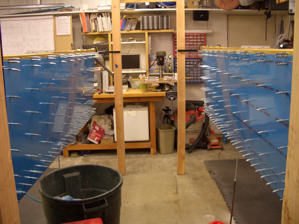
It’s late, but I just had to see what these looked like clecoed to the skeletons. I’m really glad I ordered some extra 3/32″ clecoes and I’m
really glad I have the pneumatic cleco tool. I know my hands would be killing me if I had to do this with regular cleco pliers.
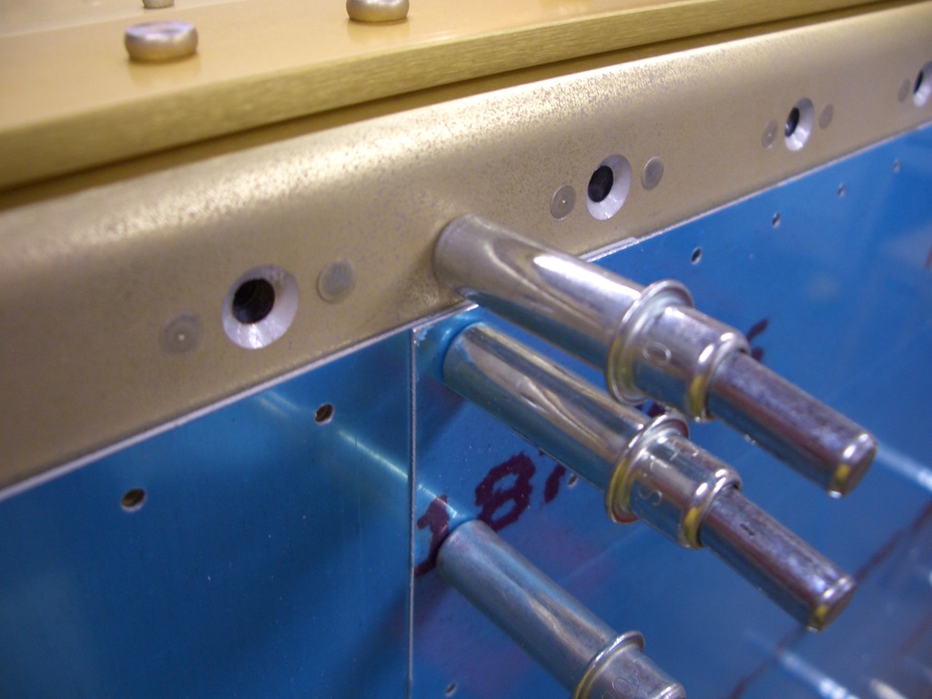
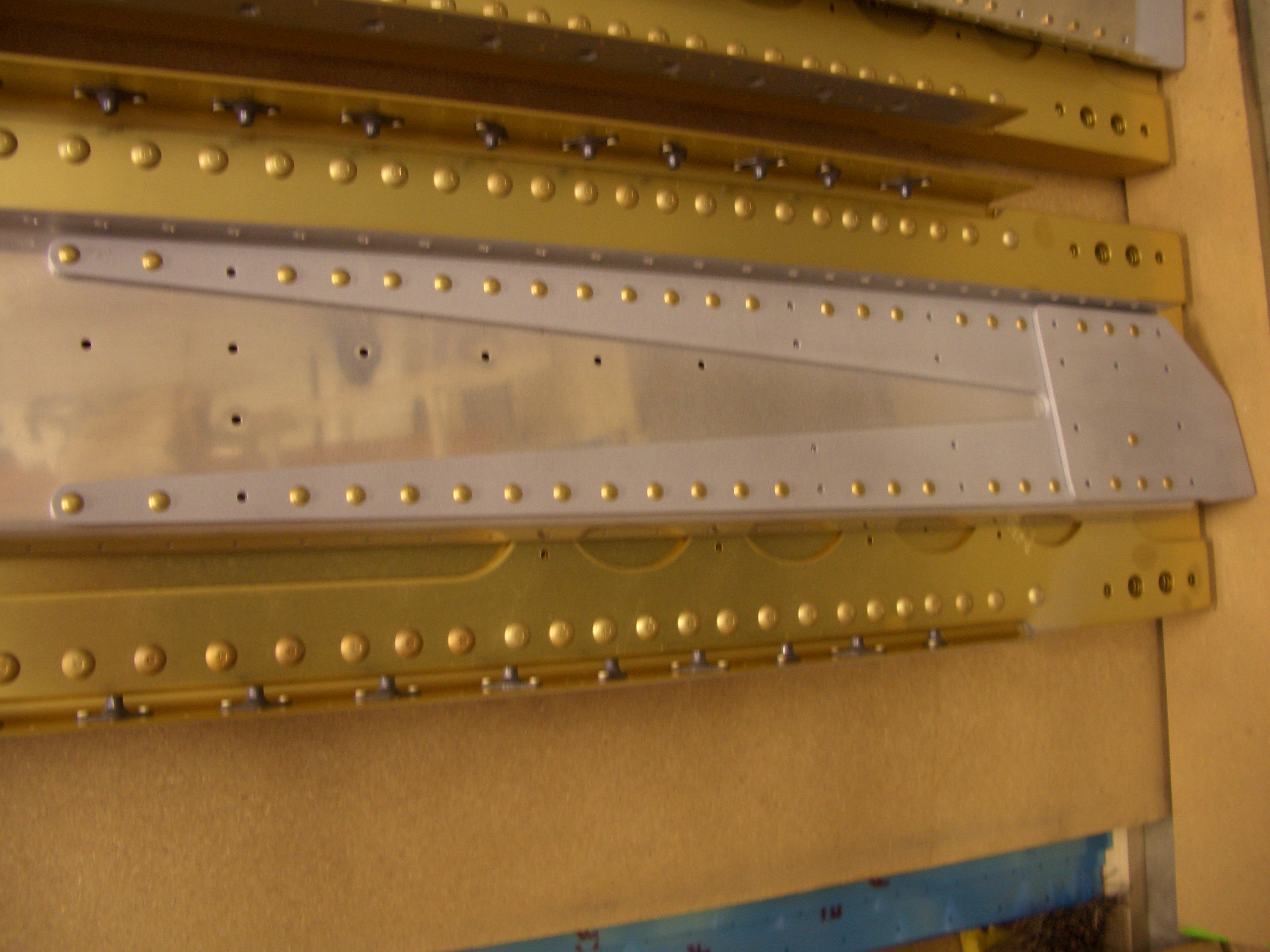
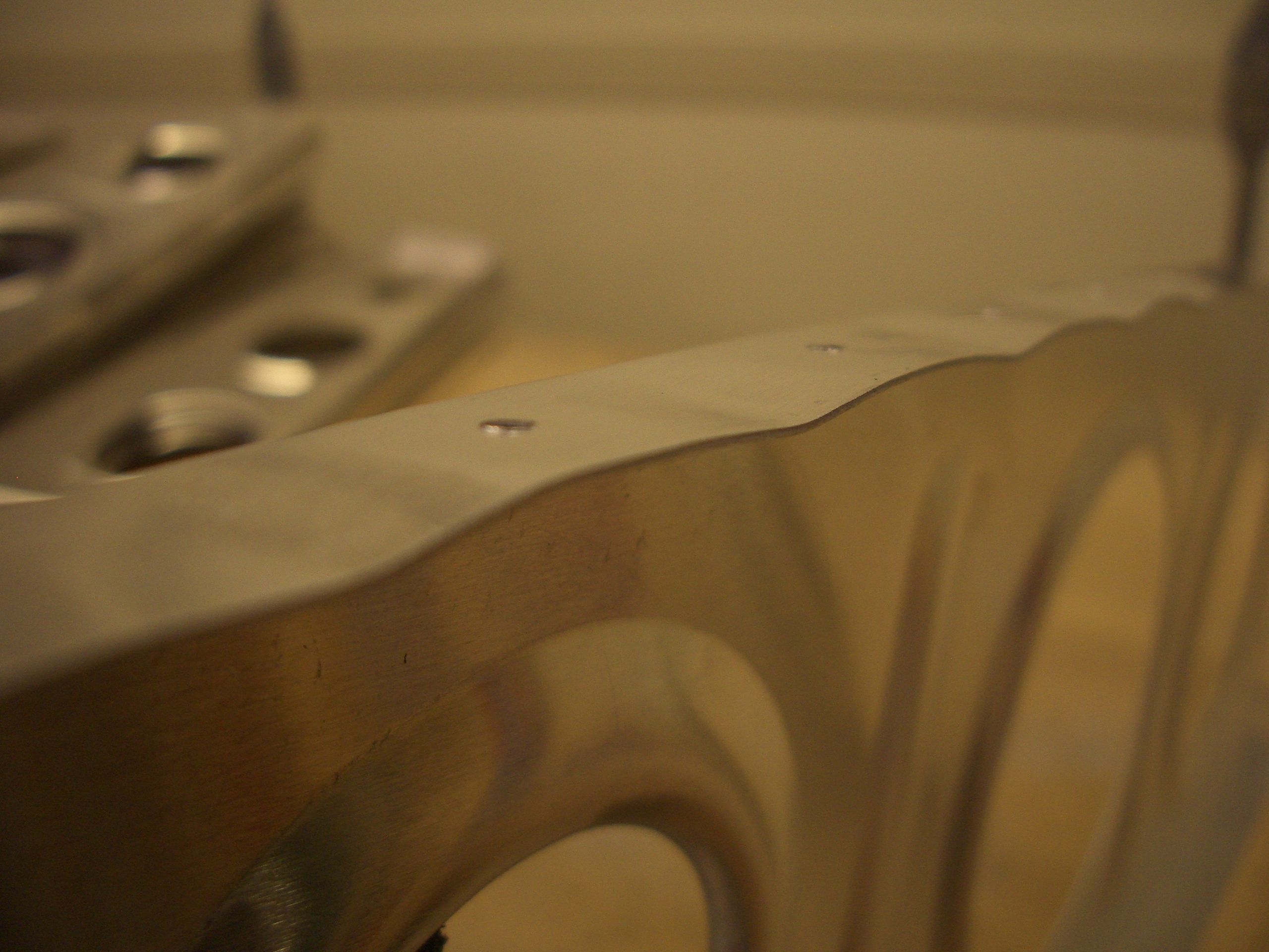
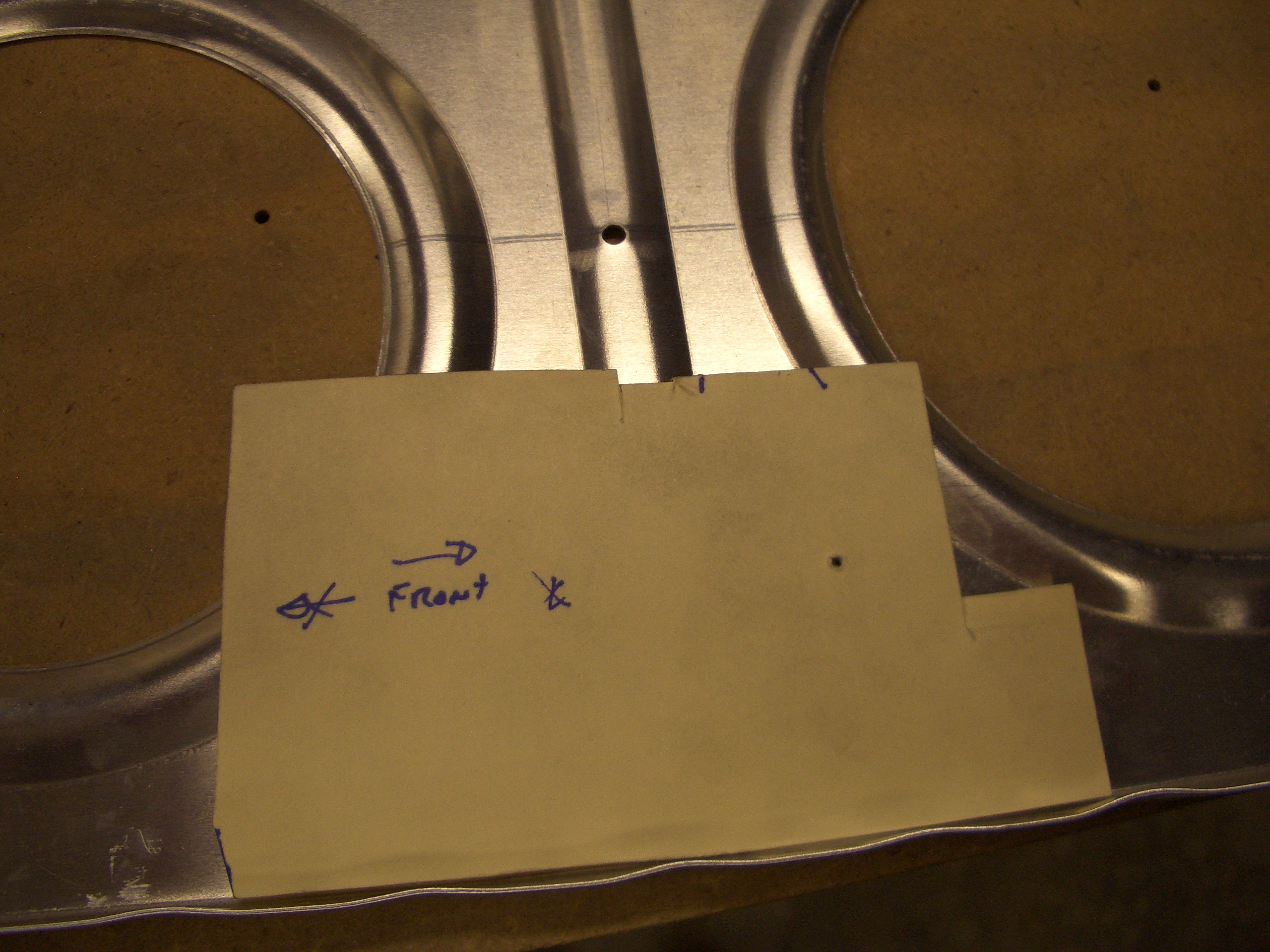
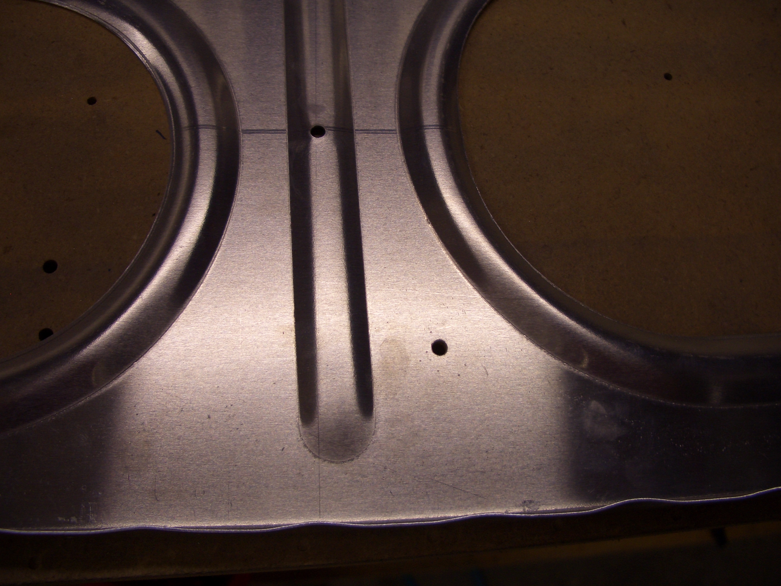
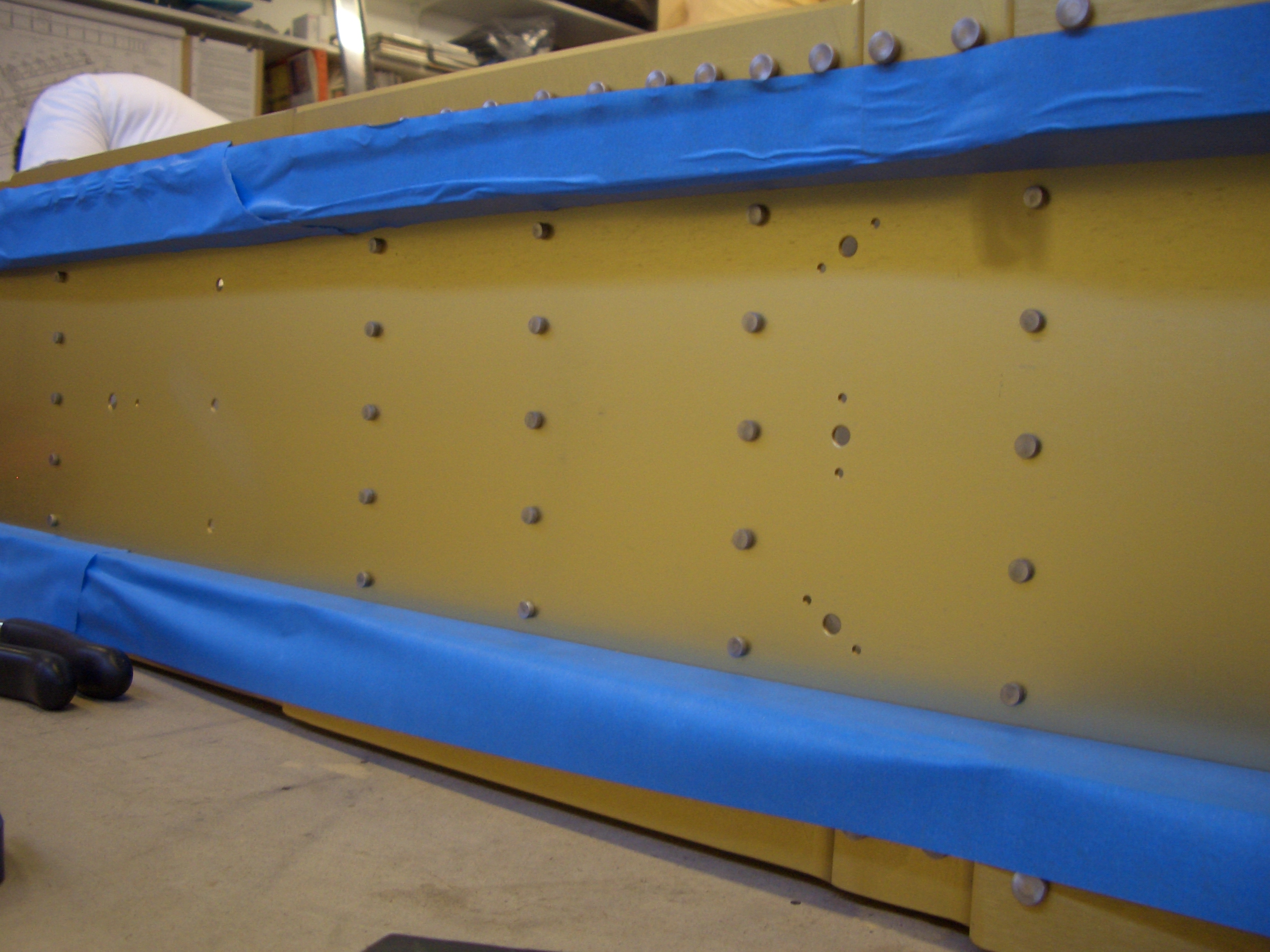
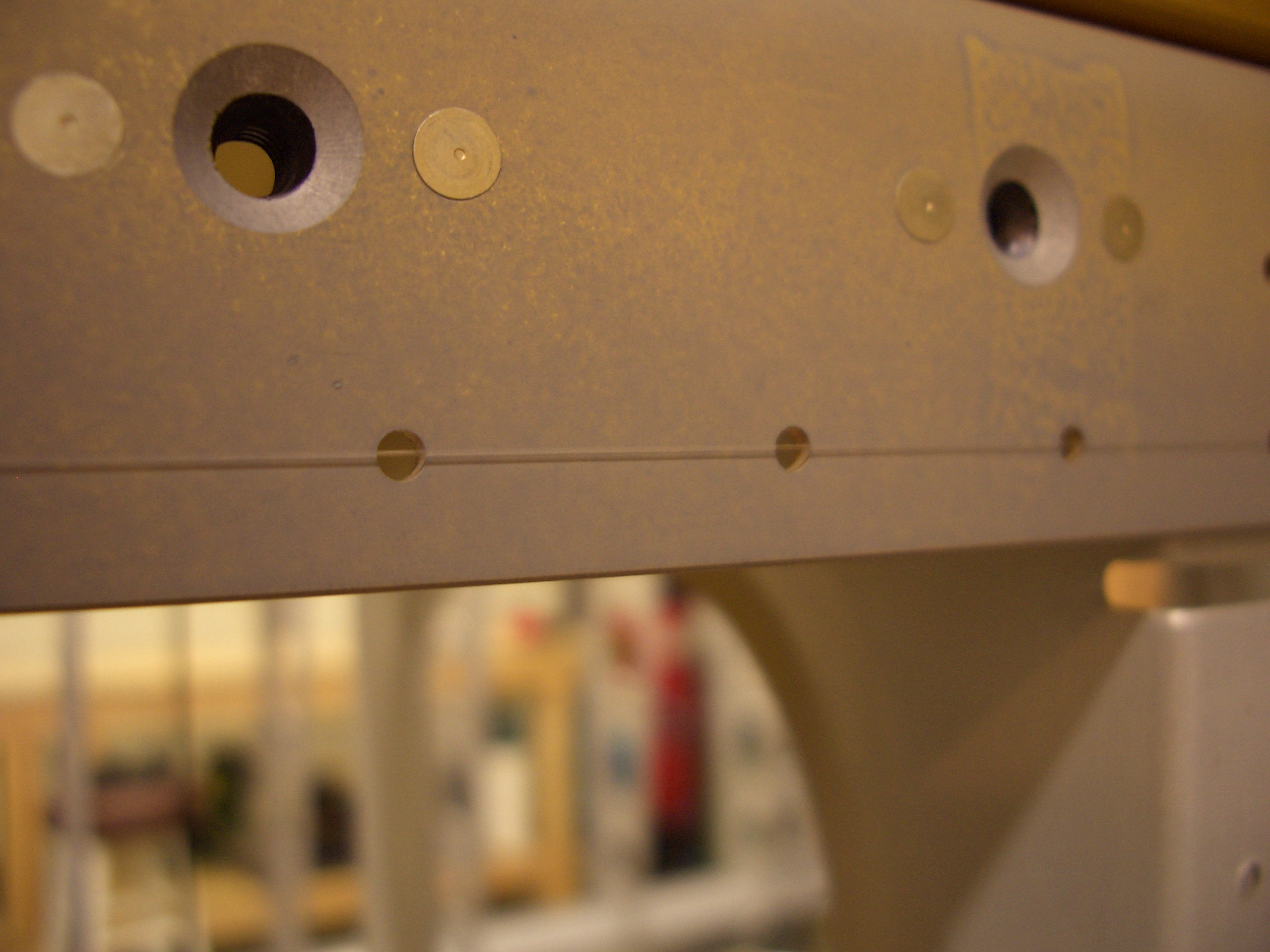
Here is a closeup of the overlap between the inboard and outboard top skins. Before riveting these on for good, I’ll create a slight bevel on these skins to reduce the bulge.