Drilled Control Cable Bracket

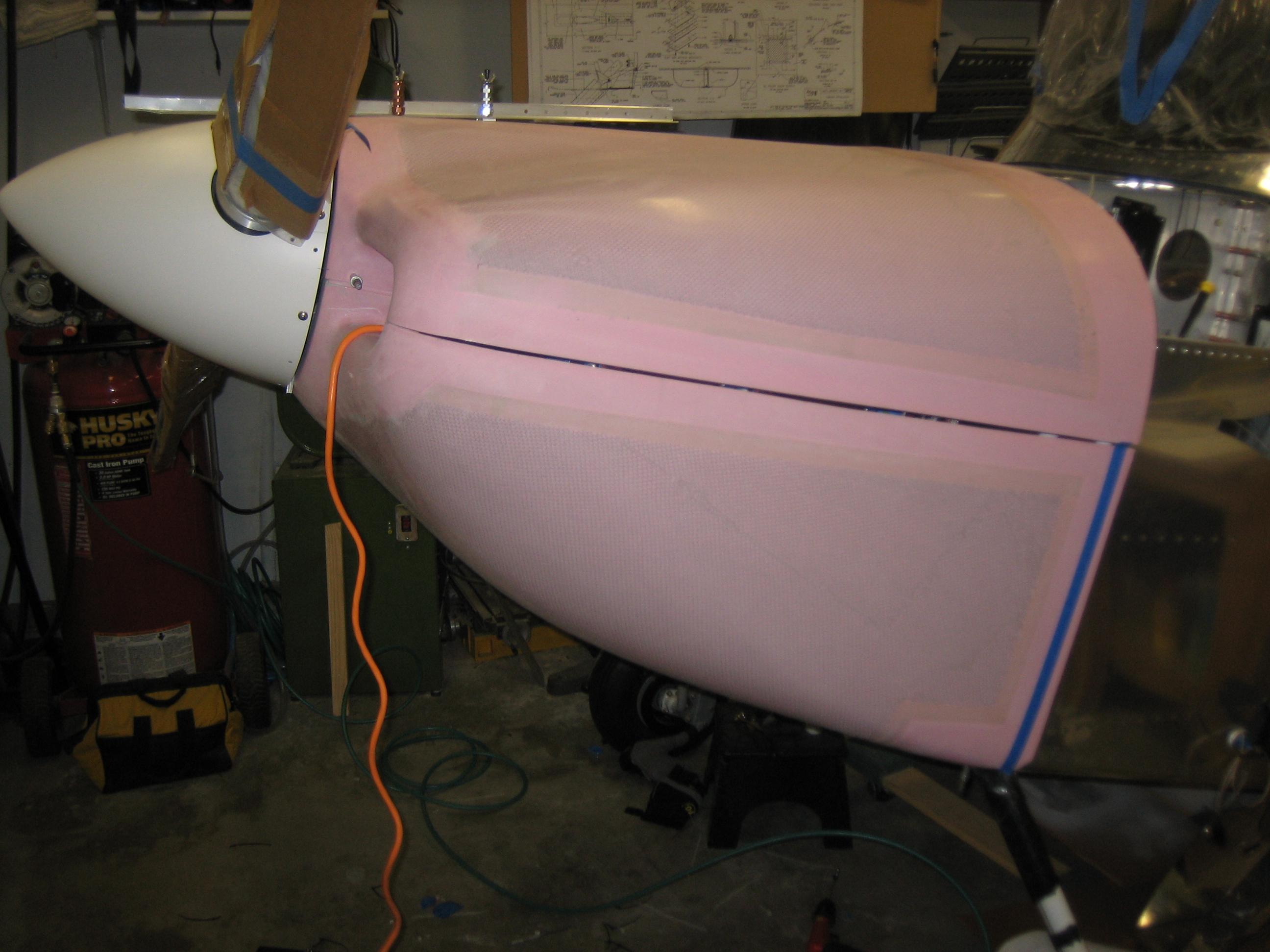
I got an email from Joe Blank at Van’s today.  After reviewing my cowl fitting issue further, they now think my cowl is made correctly and that if I trim the aft edge all the way around, I should have enough overlap on the sides to make a straight joint.

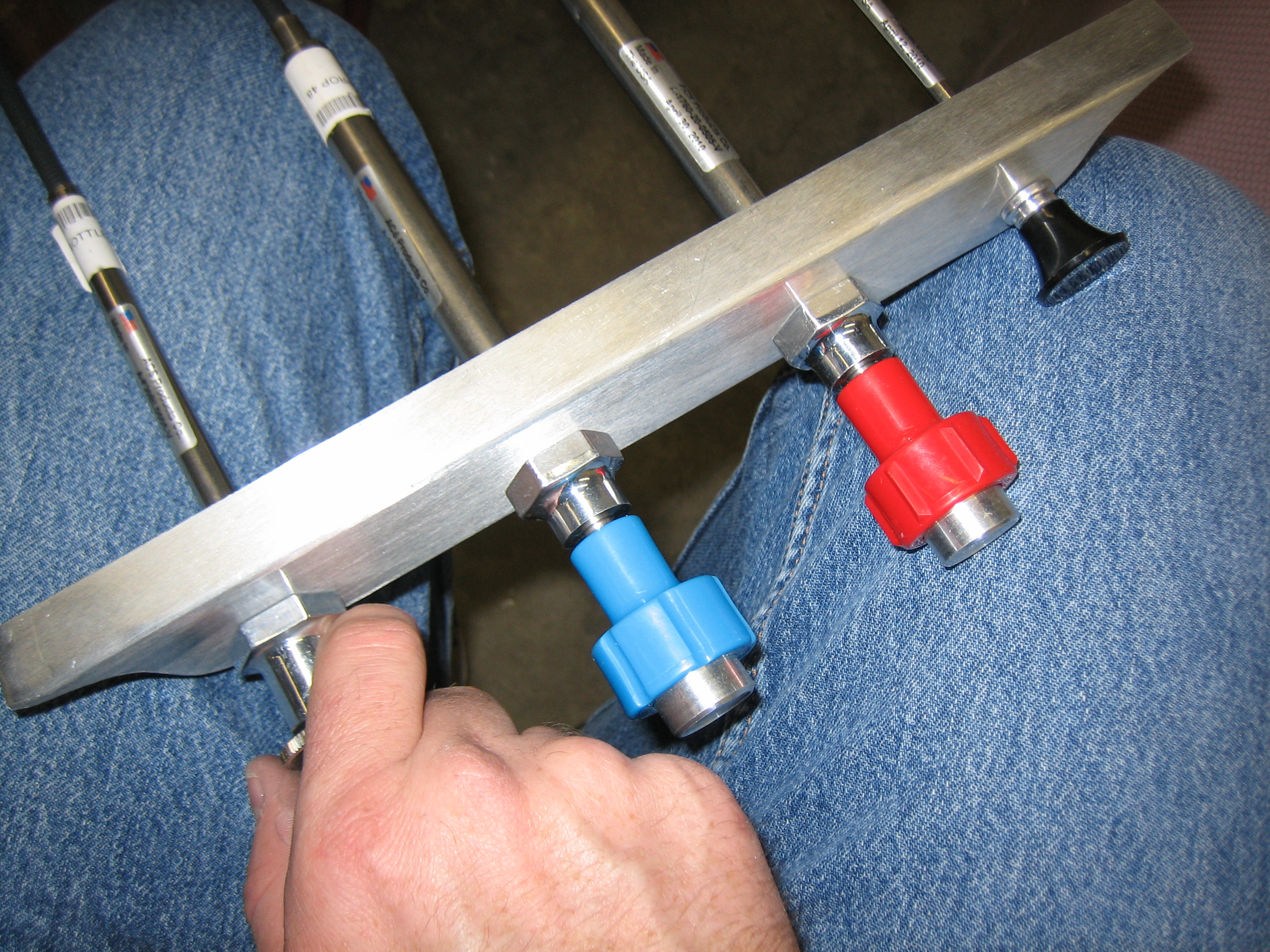
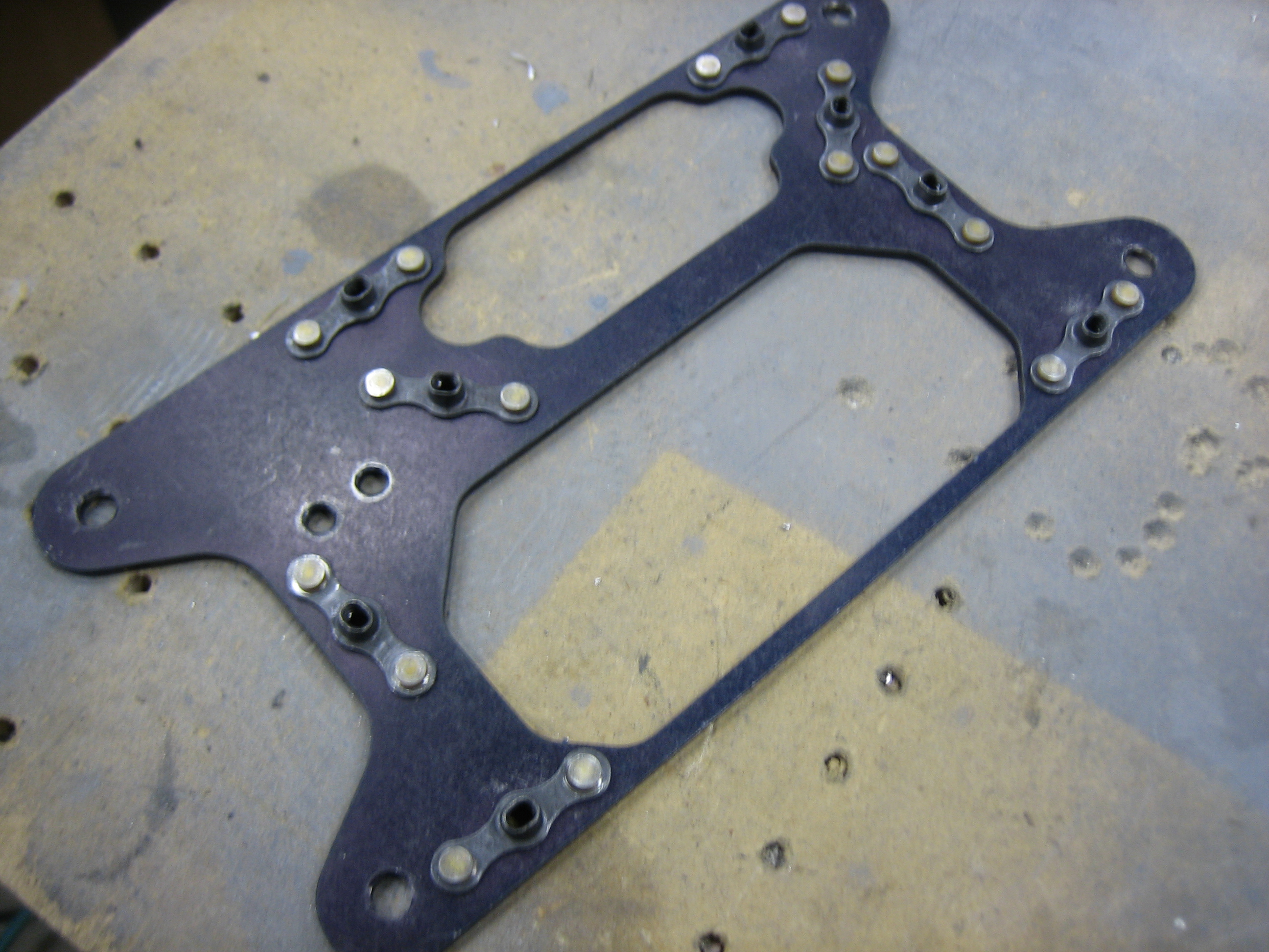
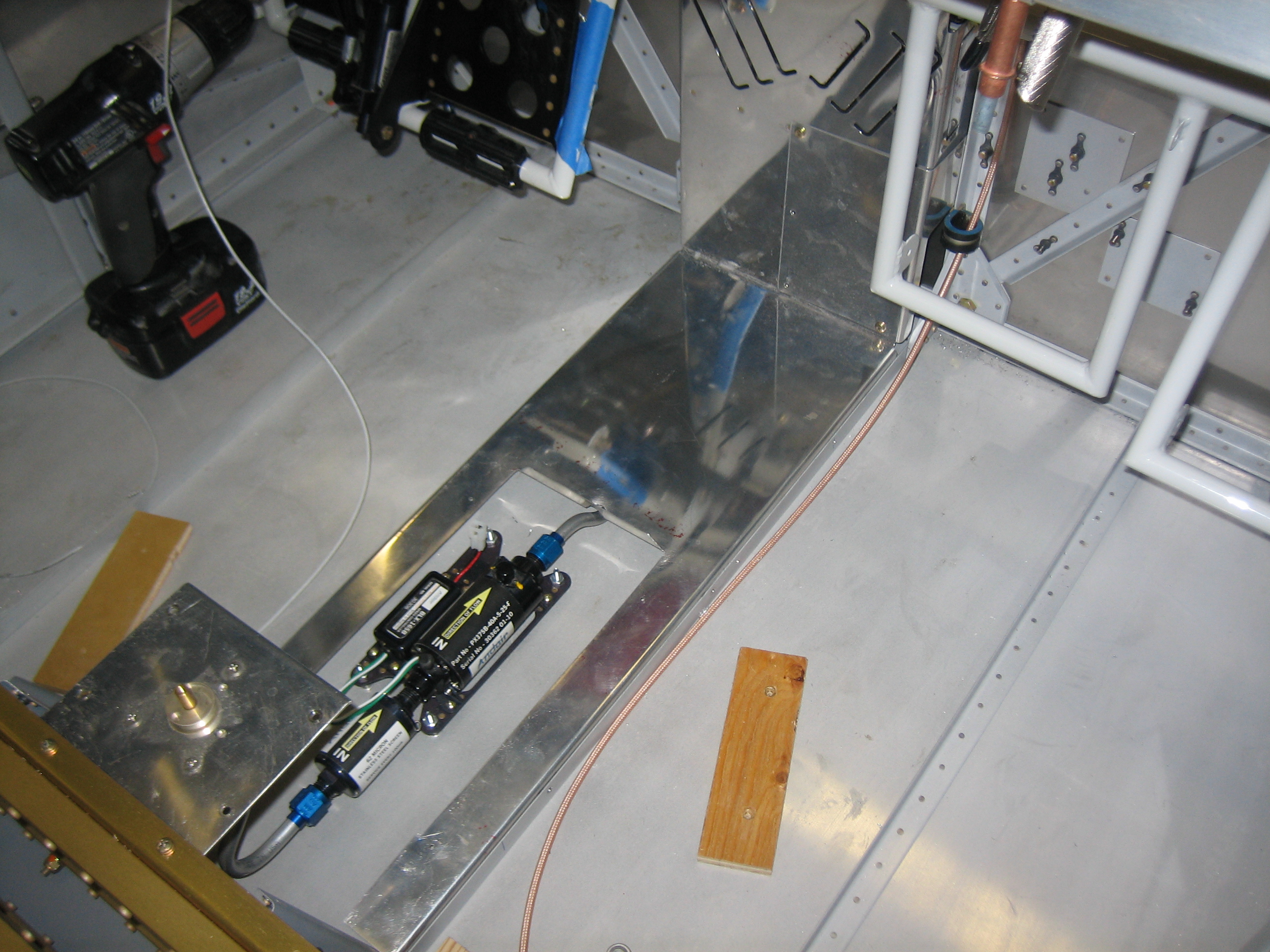
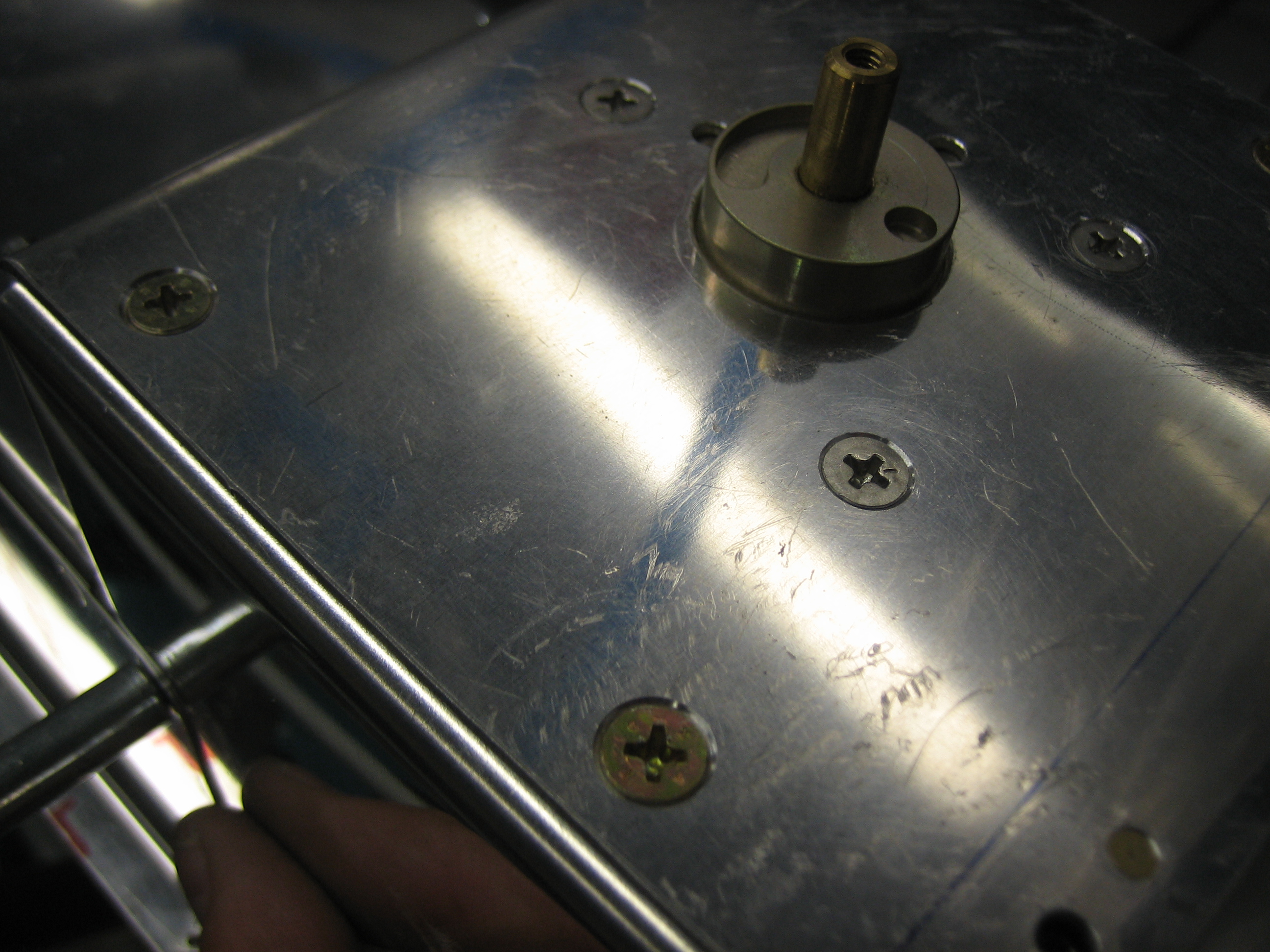
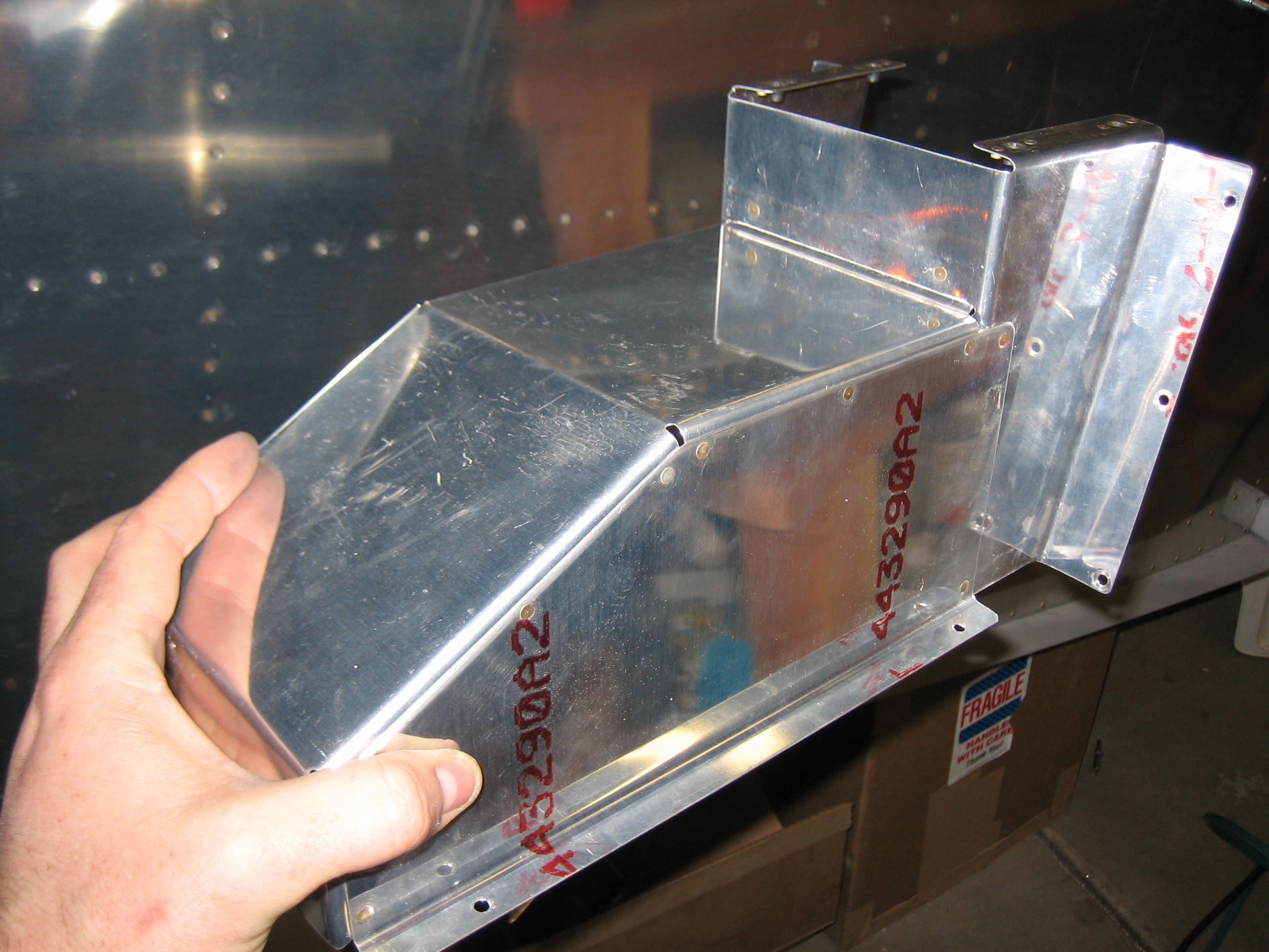
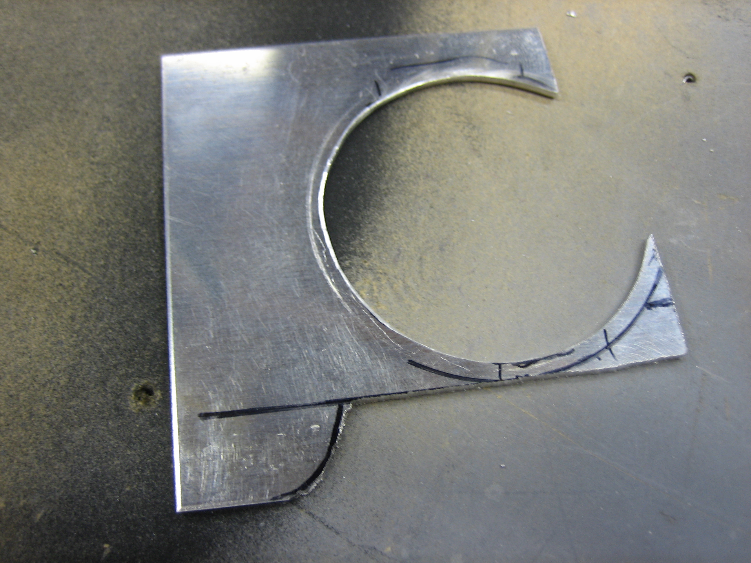
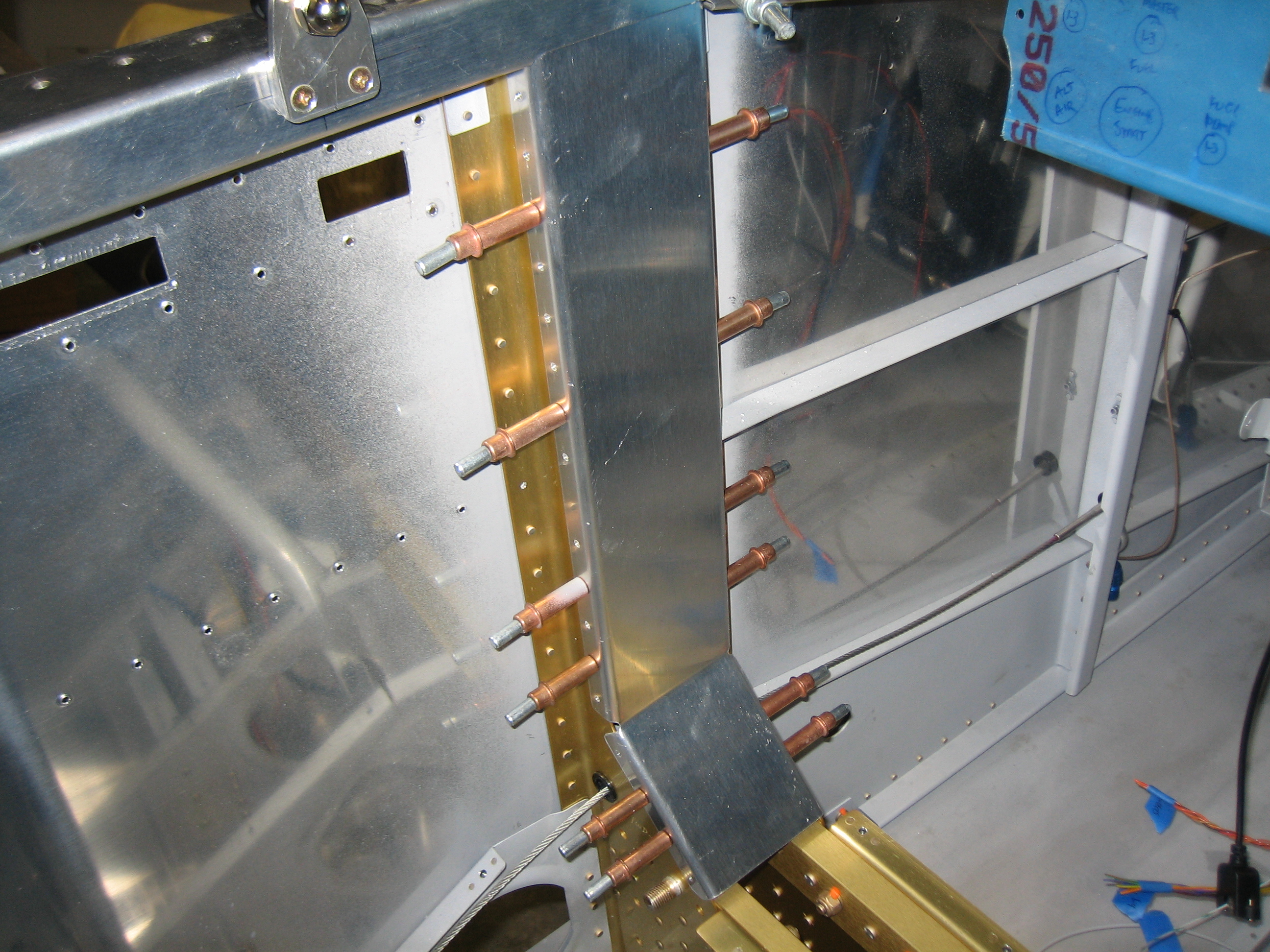
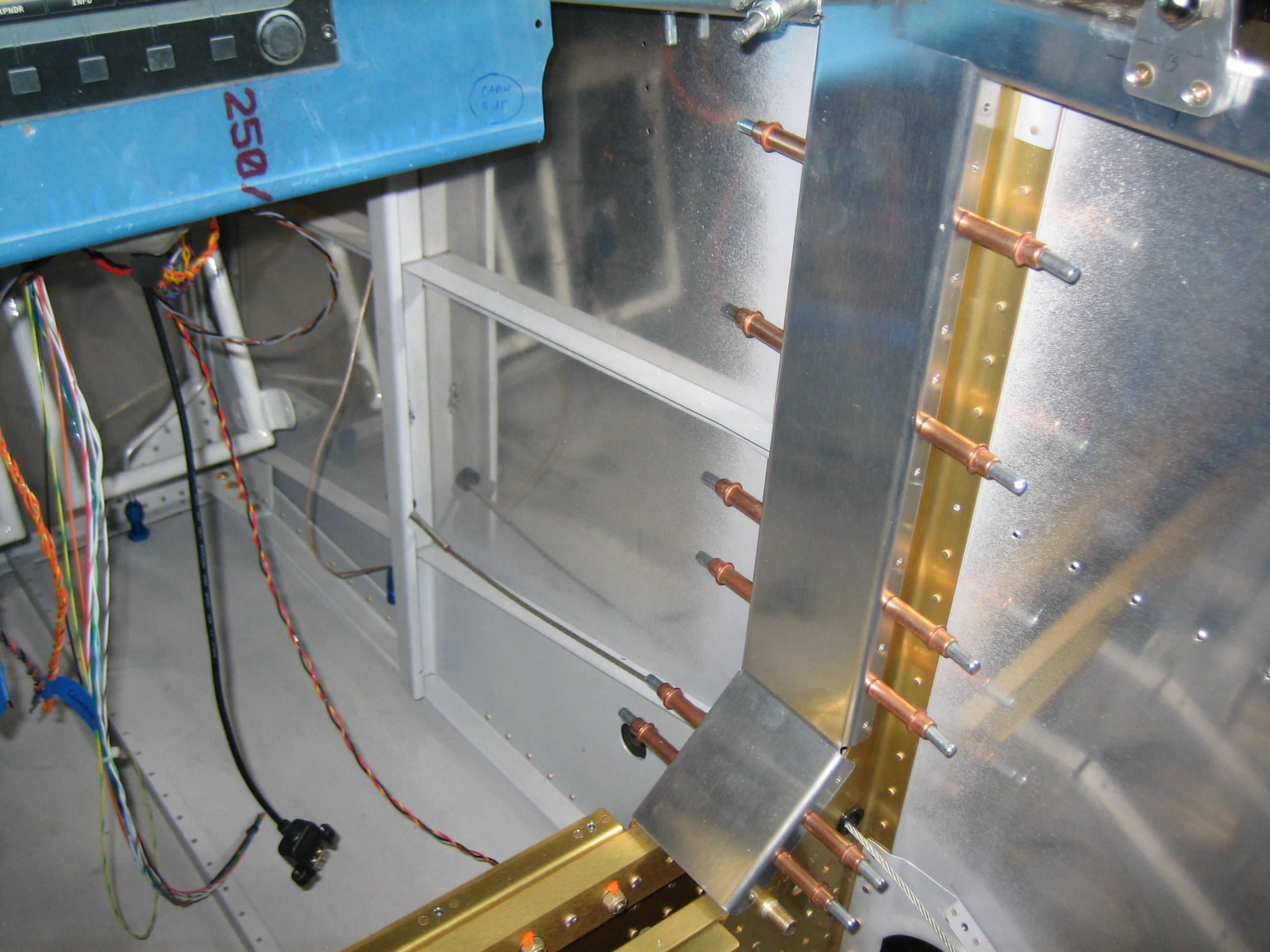
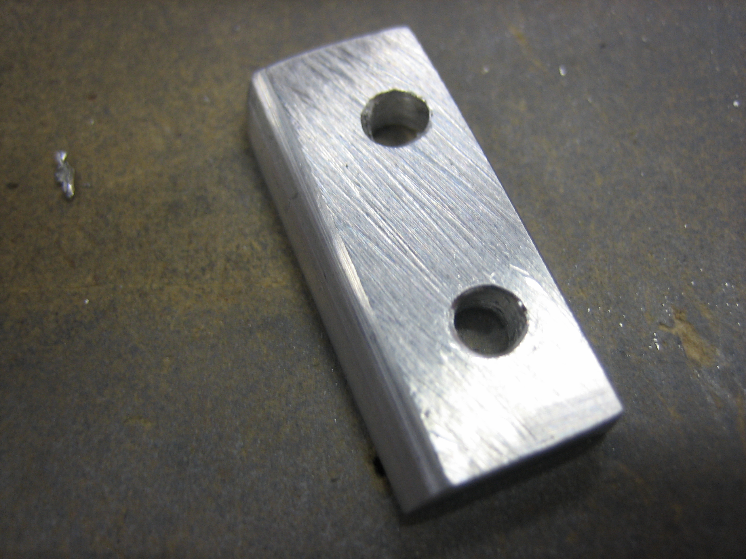
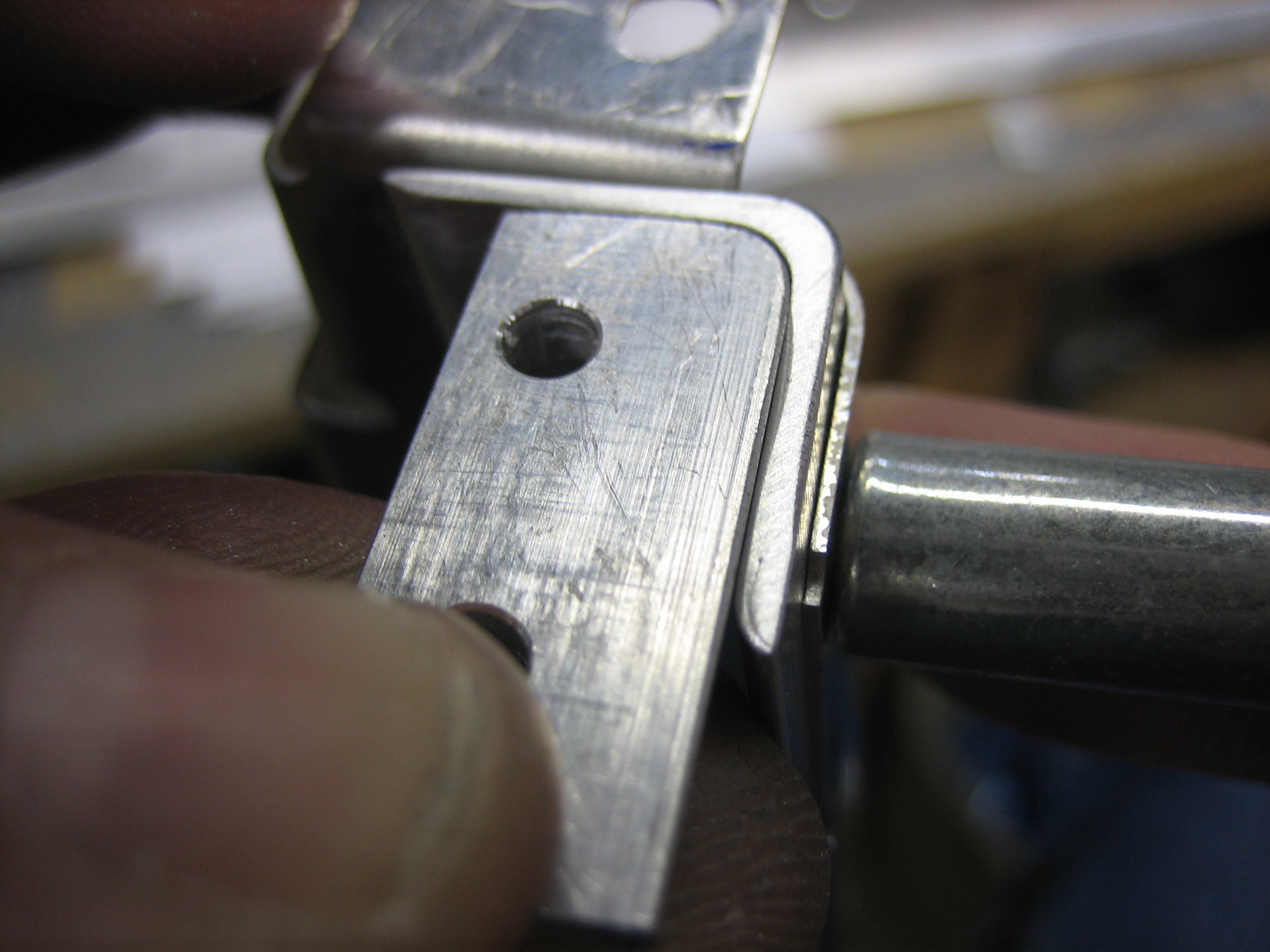
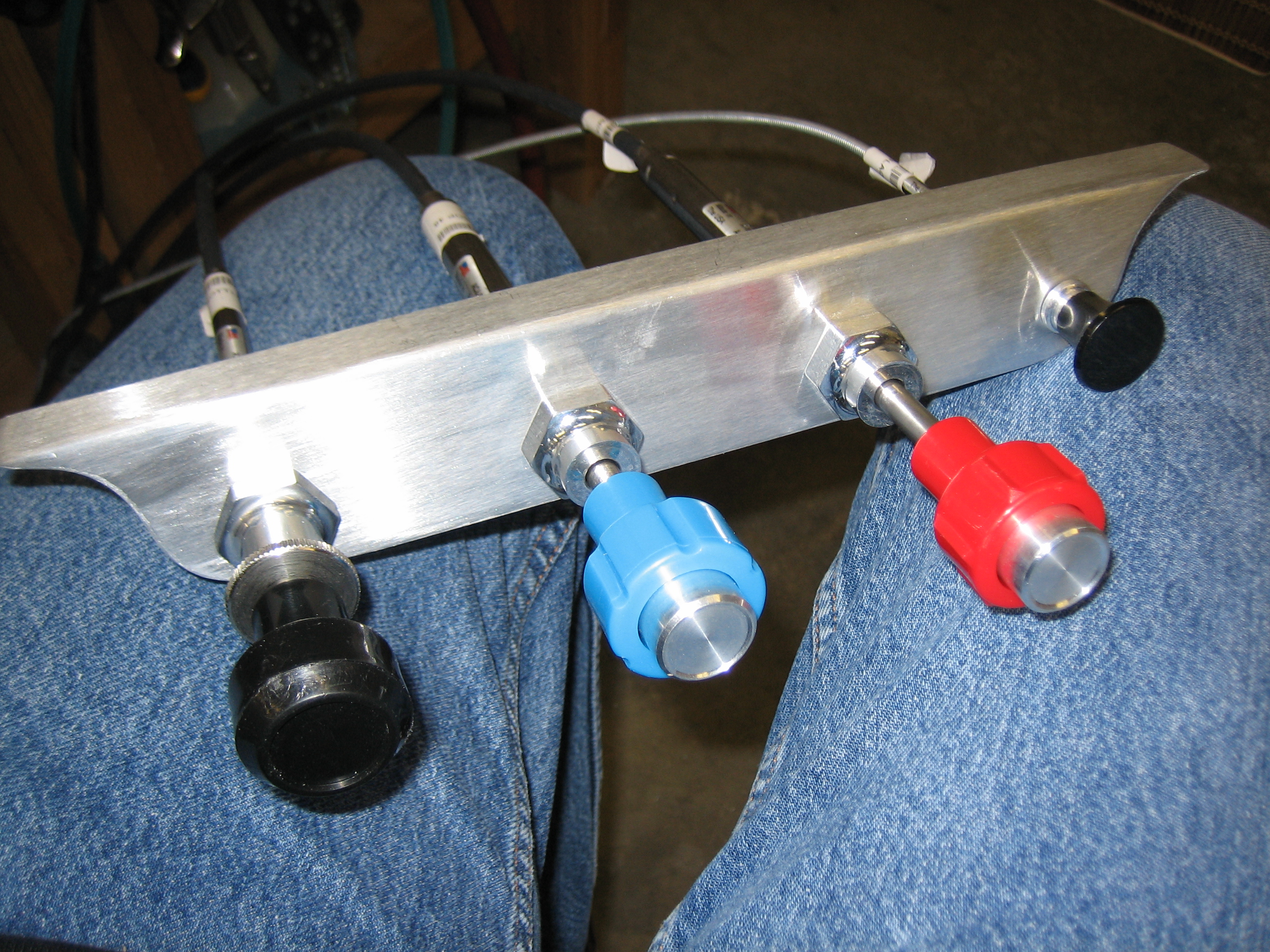
Anyway, tonight’s little project was to determine the mounting position for the control cables.  I used the stock bracket that came with the kit to mock up a potential control spacing to see if there were any conflicts before drilling the actual bracket that I bought from Experimental Air.  My original goal (and what I mocked up here) was to put the three engine controls in the center, the parking brake on the left and the cabin heat on the right.  This resulted in 2″ between the outer knobs and the outboard engine controls and about 2 7/16″ between each of the engine controls.  After playing with it for a few minutes, I decided that this was too tight and that the cabin heat knob should be removed from the bracket.

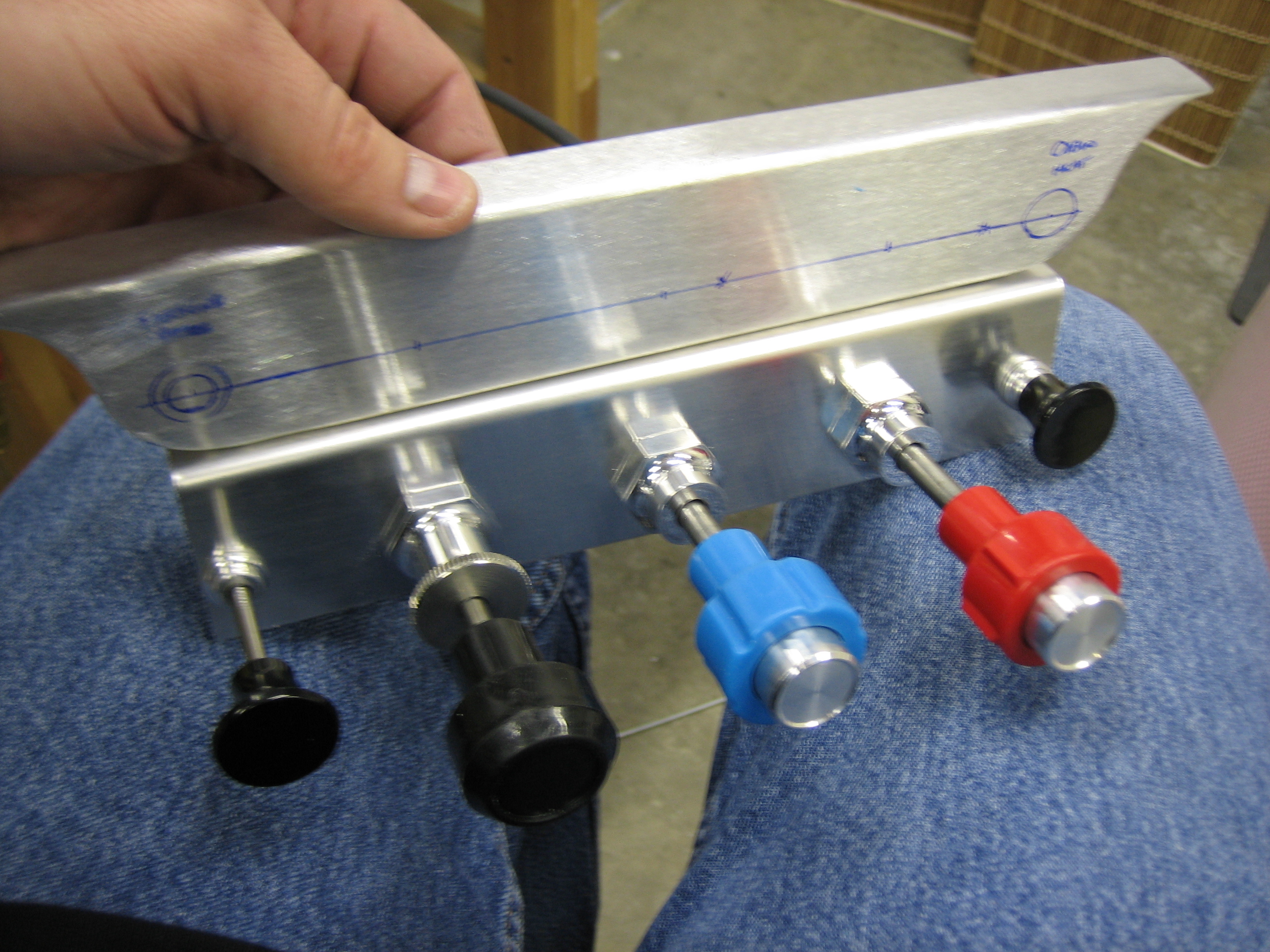
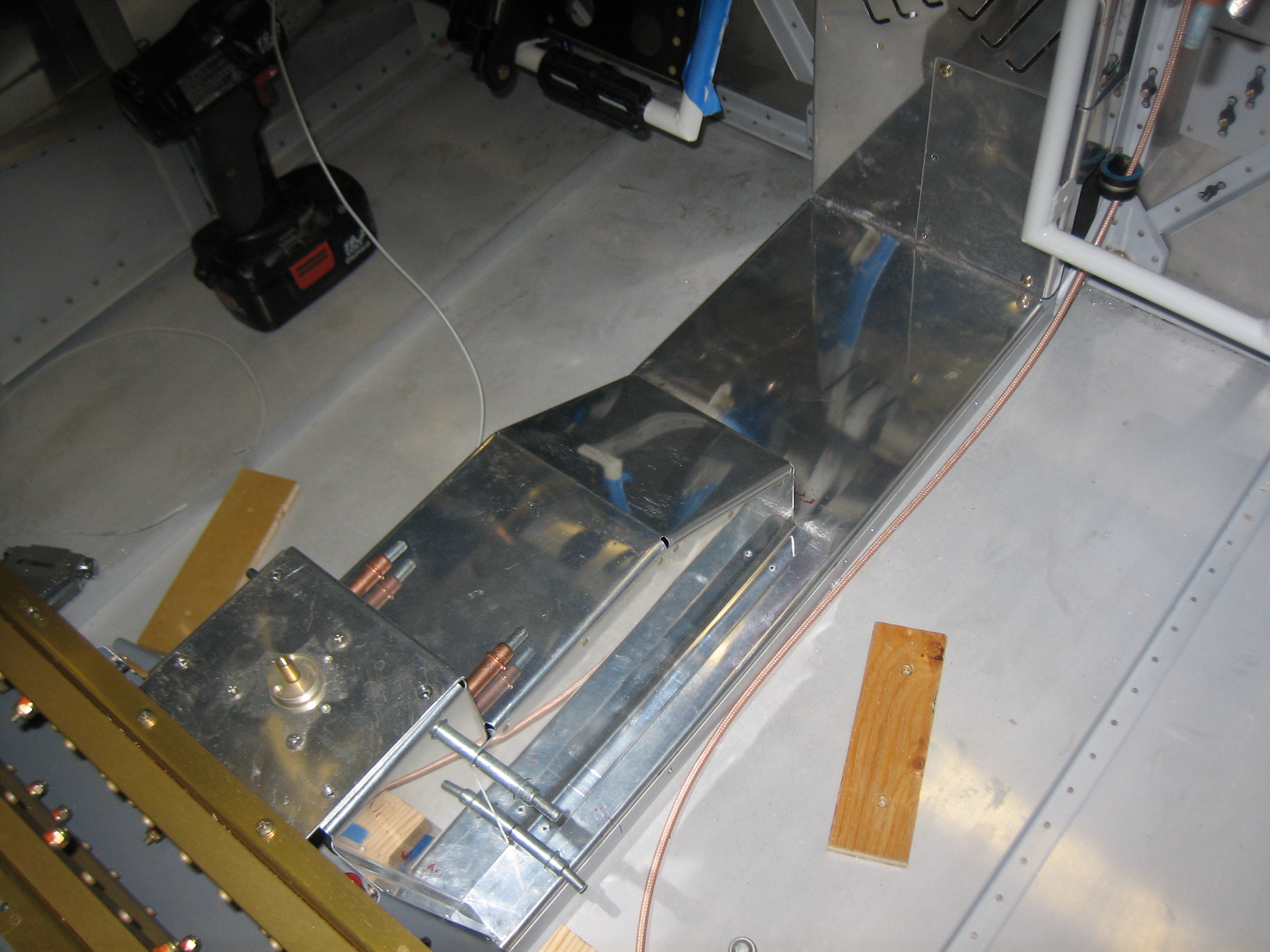
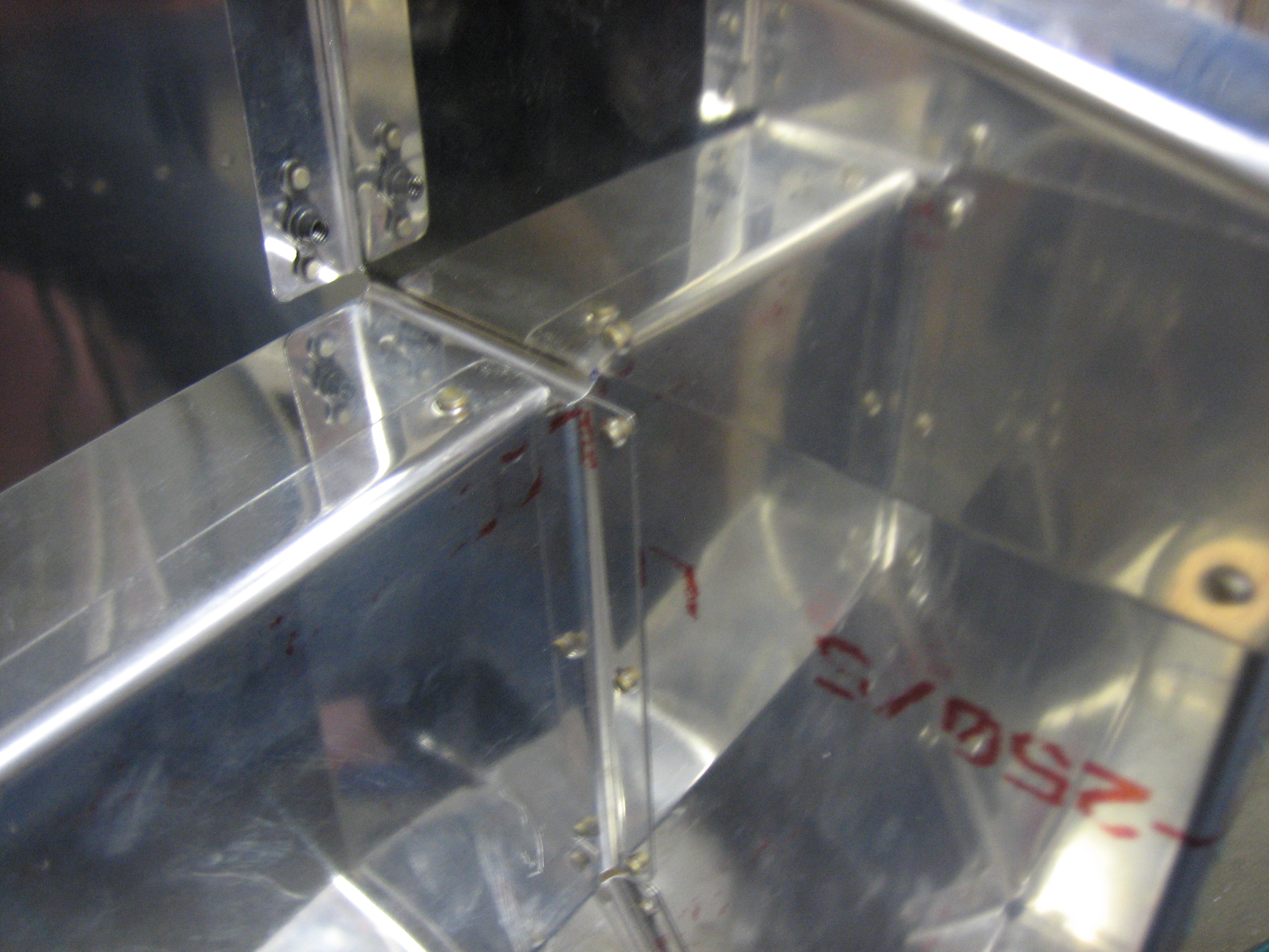
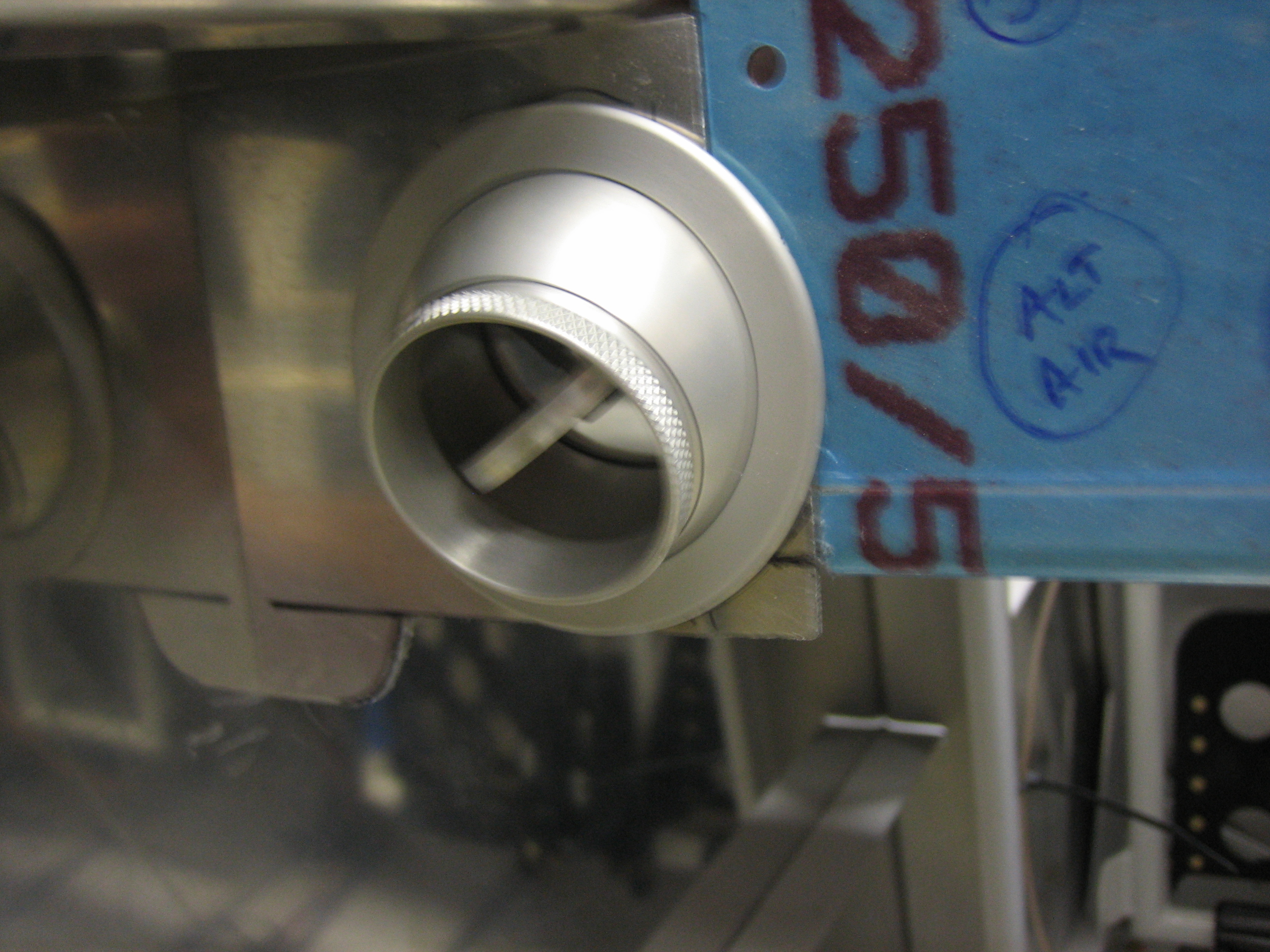
As you can see, I also moved the parking brake knob over to the right side of the bracket so that it’s out of the way.  This also has the advantage of bringing the engine controls closer to me.  The three engine controls are spaced 3″ apart and the parking brake knob is a hair over 2 1/2″ from the mixture knob.  You can also see that I drilled the holes lower than the center of the bracket.  They’re 3/4″ up from the bottom edge which leaves plenty of room to provide labels for each of the controls.

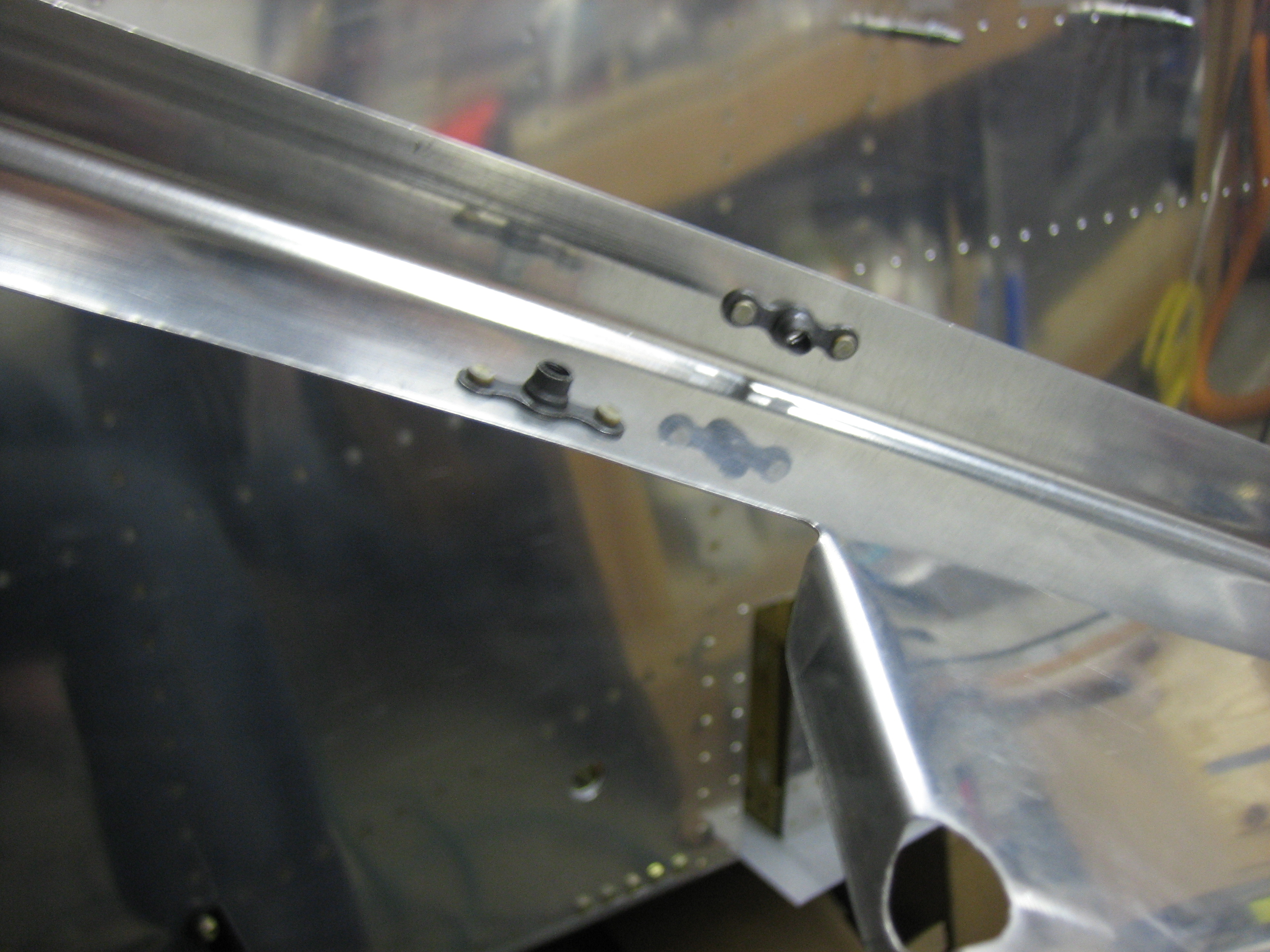
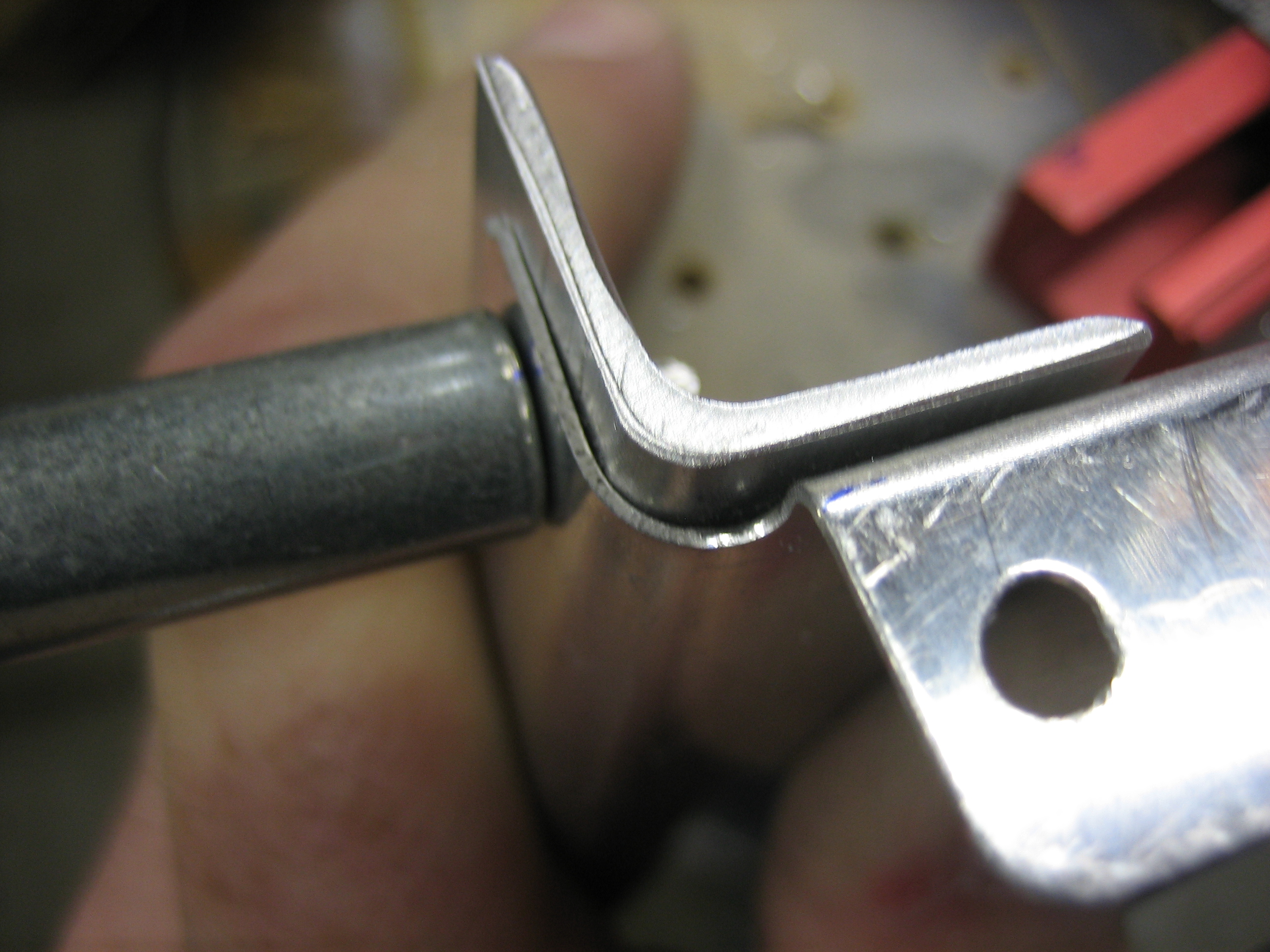
A top view shows that my hand has plenty of room when operating each knob.

Installed New Brake Lines and Bled Brakes

The last time I spoke with Brett at Bonaco, he indicated that they now have black anodized fittings, so I ordered replacement AN822-3D fittings and new hoses from the reservoir to the master cylinder with black fittings on each end.  This looks so much nicer now that everything associated with the brakes and rudder pedals is black anodized aluminum.

I torqued down all of the fittings and decided to fill the brake system tonight.  I’m using Royco 782 fluid.  I was able to find quart sizes of this at SkyGeek.com.

Royco 782 is a MIL-PRF-83282 fluid which is the replacement for MIL-H-5606 and has a much higher flash point.  There have been brake fires with MIL-H-5606, so I didn’t want to use that.

The general consensus seems to be to use a pressure system to fill the brake system from the bottom, but people sometimes still have issues with bubbles in the system.  Getting the bubbles out of the system has nothing to do with the direction you fill the system, it’s all about getting a high flow rate through the system.  If the flow rate is too slow, bubbles will get stuck in high spots in the system since they tend to migrate fairly slowly through the narrow lines.  With a high enough flow rate, the bubbles can’t help but be carried along with the fluid.

Instead, what I did was create a closed system to pump the brake fluid through.  I hooked up a fitting and hose to the brake fluid reservoir and put the other end in the can of brake fluid.  I then hooked up another hose to the fitting on the bottom of the wheel caliper and also put that hose in the can of brake fluid.  Now, as fluid is pumped out of the can and through the system, it’s returned back to the can.  All I had to do after that was operate the brake pedals fully and moderately quickly until nothing but clean fluid was being pumped back into the can.  This only took about 30 seconds on each side.  The brakes are absolutely rock solid and no leaks!

Removed Firewall Conduit and Worked on New Center Cover

I added up all the wires that will need to go through the conduit, and it was pretty clear that they weren’t all going to fit.  I could either run a second conduit down the left side, or simply run the wires through the adel clamps directly and then wrap them with a split conduit which seems like the simpler option.

I decided to order a new center section cover from Van’s.  If you recall, I had to move the electric fuel pump forward a bit because I couldn’t easily fabricate the line from the fuel selector down to the fuel filter according to the dimensions in the plans.  This was going to require fabricating a custom fuel pump cover.  I was recently putting together my interior order, and the custom cover was going to complicate the floor carpet order.  I ended up deciding the easier thing to do was move the fuel pump back so that I could use the standard fuel pump cover (and hence the standard carpet).

I also played around with wire routing under the seats.  Van’s stock location just isn’t going to work.  The RG-400 would be right at the minimum bend radius and the wires have to get routed around the control stick mounts.  I’m going to have to punch additional holes in the ribs in the location I identified yesterday.

Finally, I ordered a couple of custom circuit boards today to control the annunciator lights and for the avionics interconnect.

Installed Fuel Pump

The fuel pump needs to be spaced up off the floor a little bit because of the nutplates and protruding screws on the bottom of the fuel pump mounting plate.  I fabricated four aluminum spacers and countersunk one end of each so that it will fit over the dimples in the floor.  I didn’t get any pictures of it, but I then dimpled the floor and installed the fuel pump with some scrap hardware.  I need to order some AN509-8R12 hardware to mount it for good.

Worked on Fuel Pump Mounting

After fiddling around with where to mount the fuel pump, I decided not to mount the fuel pump to cross bars on the center cover.  I did this for a couple of reasons.  First, It means that the fuel pump has to come out if I ever need to remove the cover fiddle with the wiring.  Second, the cross bars reduce the vertical space available for wiring under the cover.  Instead, I’m going to mount the fuel pump mounting plate directly to the floor.  I do need to be able to remove the fuel pump and controller if they ever need to be serviced, and I don’t want to have to remove the mounting plate since that will require two people (one for the screws on the outside and one for the nuts on the inside).  To do that, I decided to replace all of the small metric nuts and screws with standard #6 AN hardware.  I installed nutplates on the bottom of the mounting plate.

I then used some short AN515 #6 screws to screw the pump and controller down to the mounting plate.  You can also see that I removed the terminal block and replaced it with a two connector molex connector.

Here’s where the fuel pump will be mounted.  I’ll fabricate some short spacers and the screw this to the floor.

Moving the pump down made it a lot easier to bend this fuel line between the fuel selector and the fuel filter.  There is tons of room around the fuel line, and plenty of clearance from the spar penetration holes for wiring.  This also brings the pump pretty far back which keeps it completely inside the pump cover.

Fabricated Fuel Line Between Pump and Firewall and Worked on Covers

I fabricated the fuel line that runs between the fuel pump and the firewall.  I had previously fabricated this line, but that was for the old pump position and that line would no longer work.  Despite the pump being farther back, this line is shorter because it takes a more direct route.

The line steps down immediately after leaving the pump to go under the cover and then bends slightly to the right to head directly to the firewall penetration.

I cut away a good chunk of the cover so that it can drop in over the pump.  This is so much better than old way I was installing this.  That would have required removing the pump to access the wiring bundle.  I bent a flange in the forward end of the cutout to stiffen the cover in this spot.

The line just touched the forward end of the cutout, so I used my Dremel and sanded away a relief.  There is about 1/4″ of clearance around the line now and nothing can flex that far.  I might still add some silicone wrap here though.

Here’s what it looks like with all of the covers in place.  With everything in its final position, I drilled the cover to the holes that were already in the floor stiffeners

I pulled everything apart to install nutplates and prep everything for final assembly.  While I had the fuel selector mounting plate off the plane, I countersunk all of the screw holes.  I didn’t realize until after doing this that the three holes near the fuel selector didn’t need to be countersunk since there is a cover plate that mounts over this.  It won’t matter though since these will be hidden under that plate.

Fuel Pump and Covers

I riveted the pump cover to the fuel selector cover.  Some people use screws to attach these, but I can’t see why you’d ever care to remove one without the other and rivets are simpler and lighter.

It’s a little hard to see what this is, but it’s a picture of the inside of the two pieces above.  I cut away most of the front of the fuel selector cover since the extra metal inside here served no purpose.

I also installed nutplates on the forward cover.  These allow the forward cover to be attached to the floor stiffeners as well as allowing the pump cover to be attached to the forward cover.

I cleaned the floor well and attached some adhesive tie-wrap mounts.

This is a closeup of the tie-wrap mounts.

I added loose tie-wraps to all of the mounts and then ran wires for the fuel pump.

The ground wire attaches to the firewall ground block and the power wire connects to the VP-X.  I’m really liking wiring with the VP-X since it allows you to do all of the wiring without having to have the panel design done or in the plane.  Once the panel is cut, I just need to run a sense line from the VP-X up to the switch and then the fuel pump wiring is done.

Started Fabricating Vent Brackets and Worked on Cowl

I started fabricating one of the brackets that will be used to mount the air vents.  These are fabricated out of 0.063″ stock which is the same as the instrument panel.

Here’s how it fits in the plane.  You can see how it nestles nicely up against the instrument panel and the flange of the vent overlaps both.  I’ll cut off the lower right of the bracket at the small horizontal black line and let the bracket follow the curve of the vent around to the bottom.  I left the bracket a little tall on the left side for now since I had Classic Aero Designs fabricate the side panels to the original height of the vent brackets.  I don’t know if they’ve cut these parts yet, so I’ll see if they can still change them.  If so, I’ll cut this off straight.

I reinstalled the cowl so that I can continue the fitting.  I had previously put this on hold while Van’s evaluated whether the flanges on the cowl sides were cut too short but haven’t gotten back to it until now.

I had previously cut the aft edge of the bottom cowl to length, so I carefully lined up the cowl all around and drilled a couple of holes on each side to the stainless steel hinge to lock the bottom in position.

I put a work light inside the cowl and marked the approximate cut line on the sides.  It’s too late to run the cutoff wheel tonight, so this is a good place to stop.

Worked on Armrests

The armrests are pretty flimsy as designed.  I’m using some 0.063″ angle to reinforce them.  I used a router to radius the outside corner so that it can tuck into the angle on the armrest.  I drilled them to the flange and will eventually also drill them to the top surface of the armrests.

I also fabricated four of these little supports that will rivet into the bulkheads at each end of the armrests to transfer the load directly into the bulkheads instead of through the wimpy flanges on the armrests.

Here’s how these will mount.  Any load on the armrests will be transferred into the 0.063″ angle.  The angles will sit directly on top of the supports to transfer the load into the bulkhead.  Without these, that little flange just above the angle would have to carry the load.