Reverse Trim Control Resolved

Vertical Power released version 1.3 of their VP-X firmware today.  I installed it and it resolved the issue with the reversed trim buttons on the SkyView.  Now, whether I press the coolie hat on the stick to the right or press the “Right” button on the SkyView, the stick goes right.

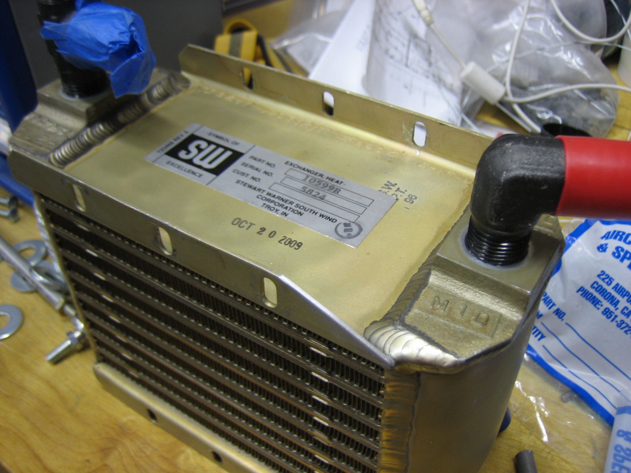
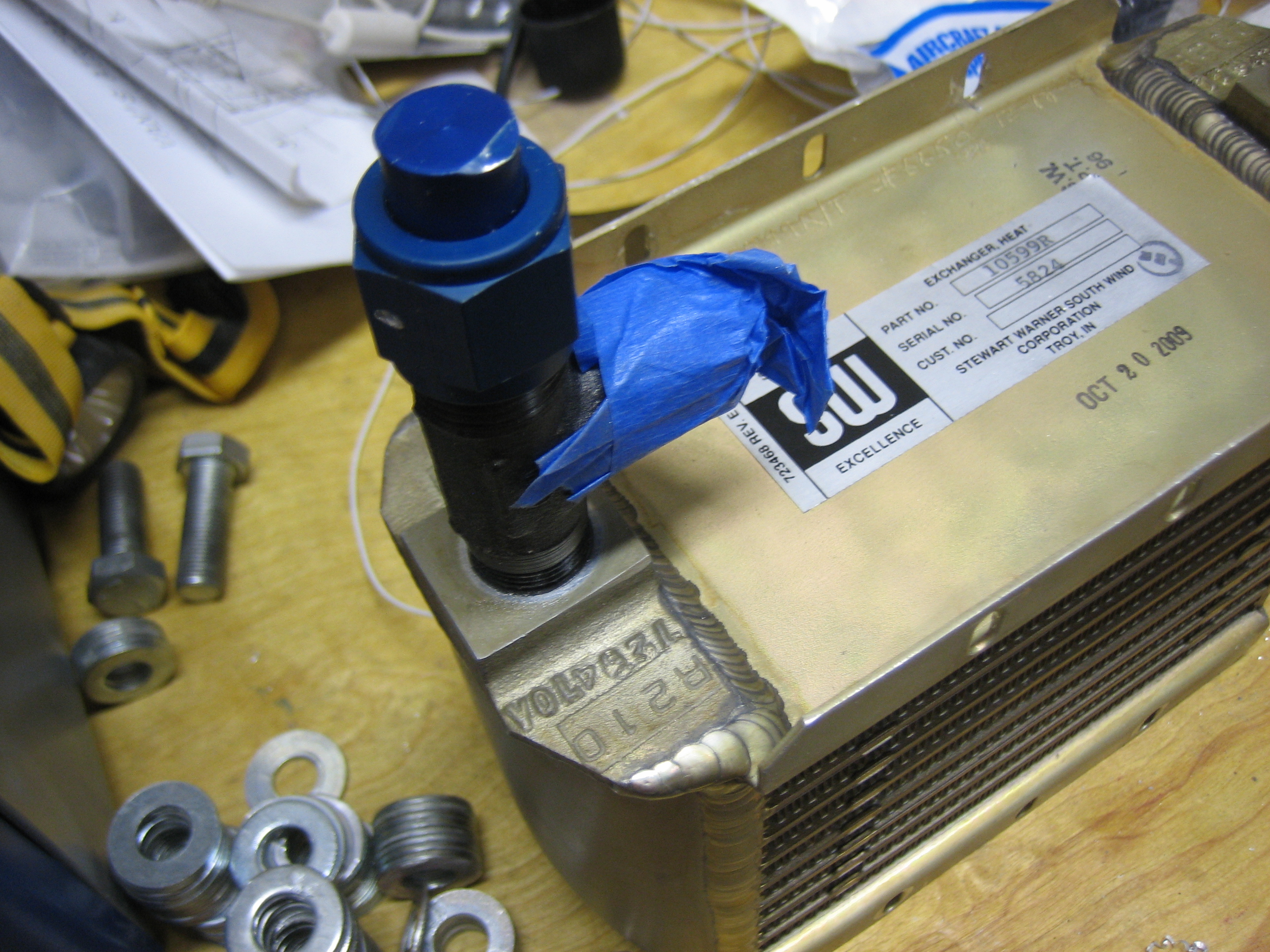
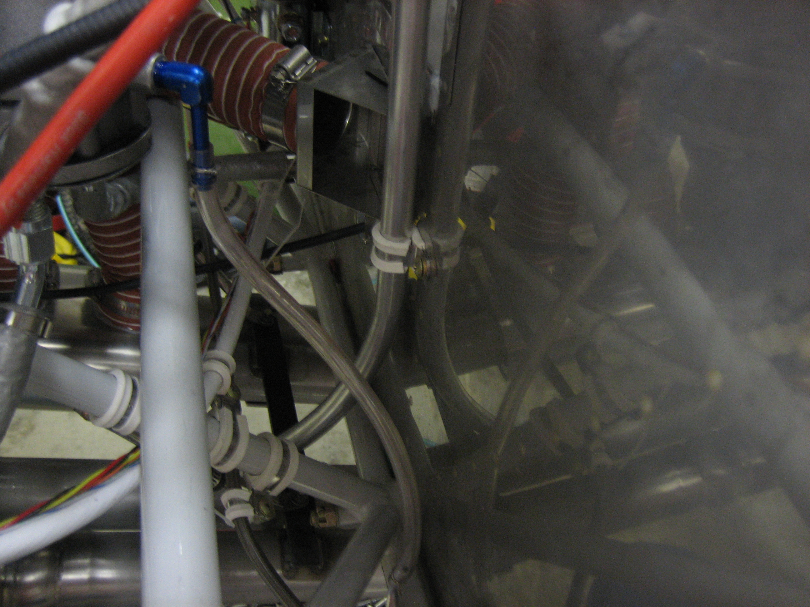
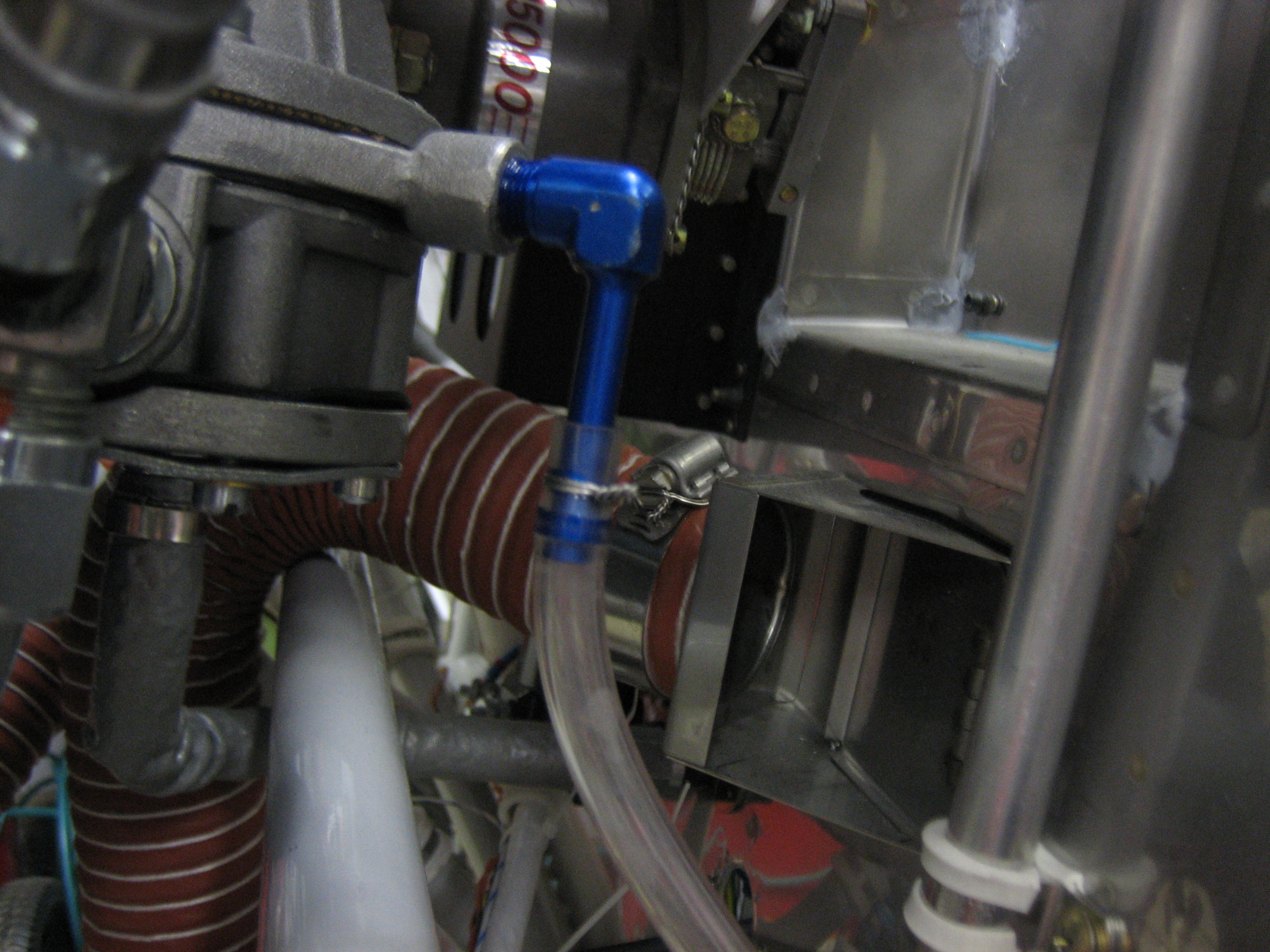
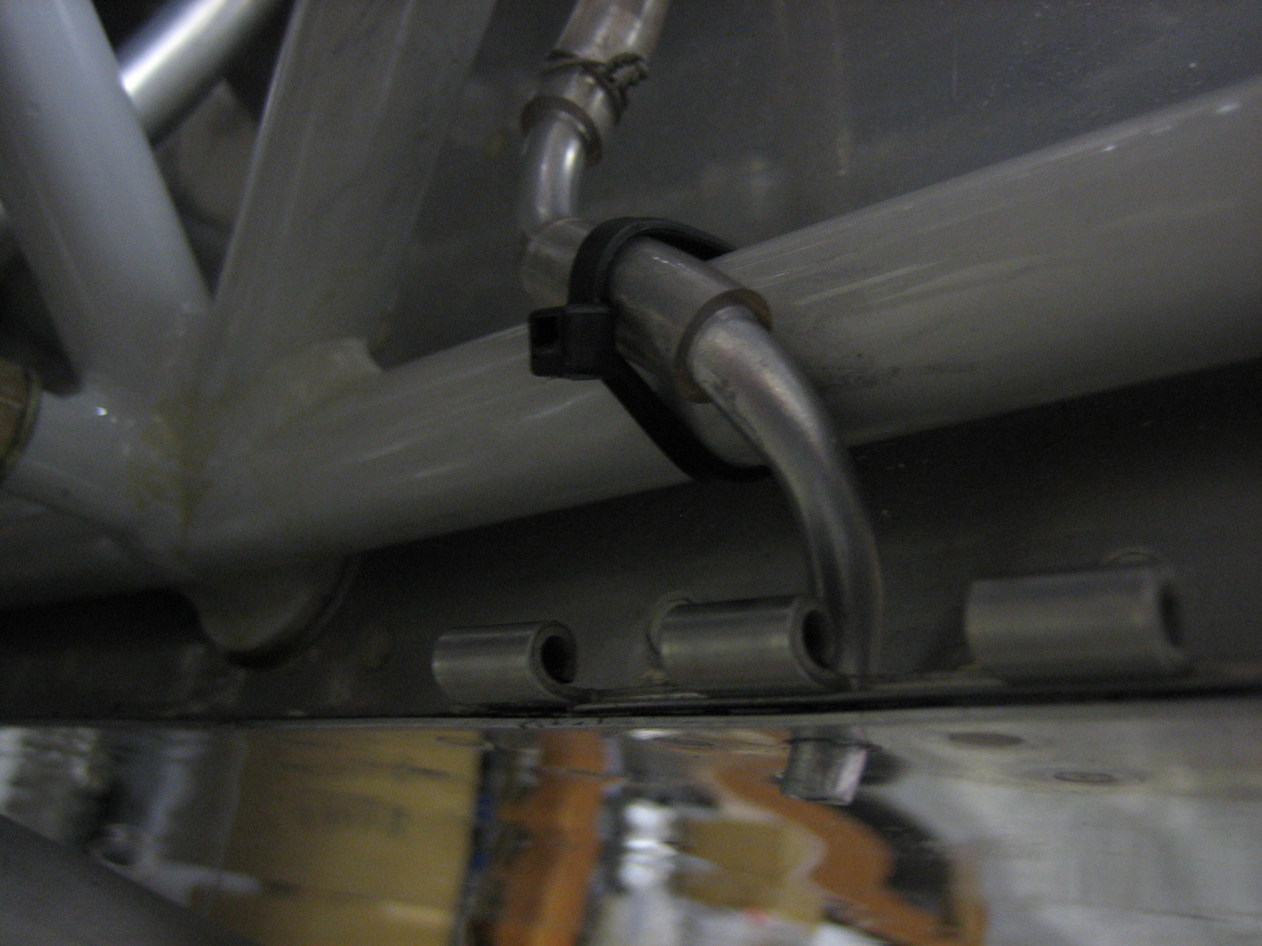
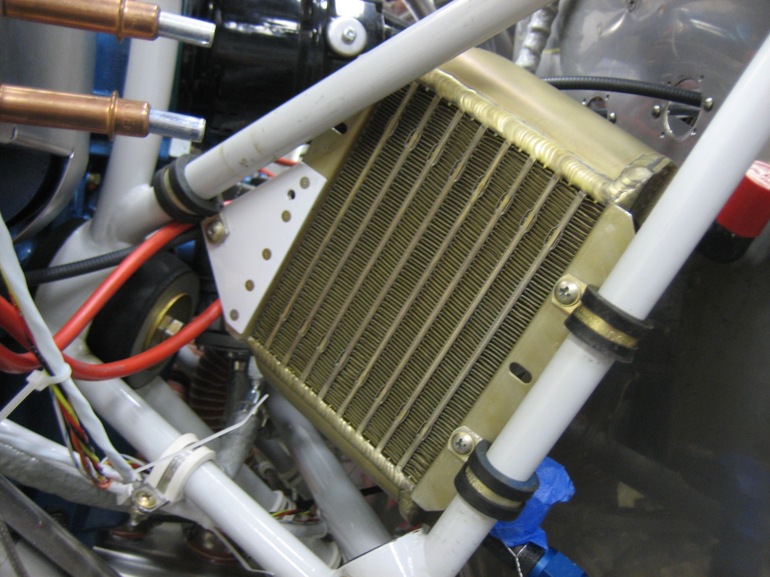
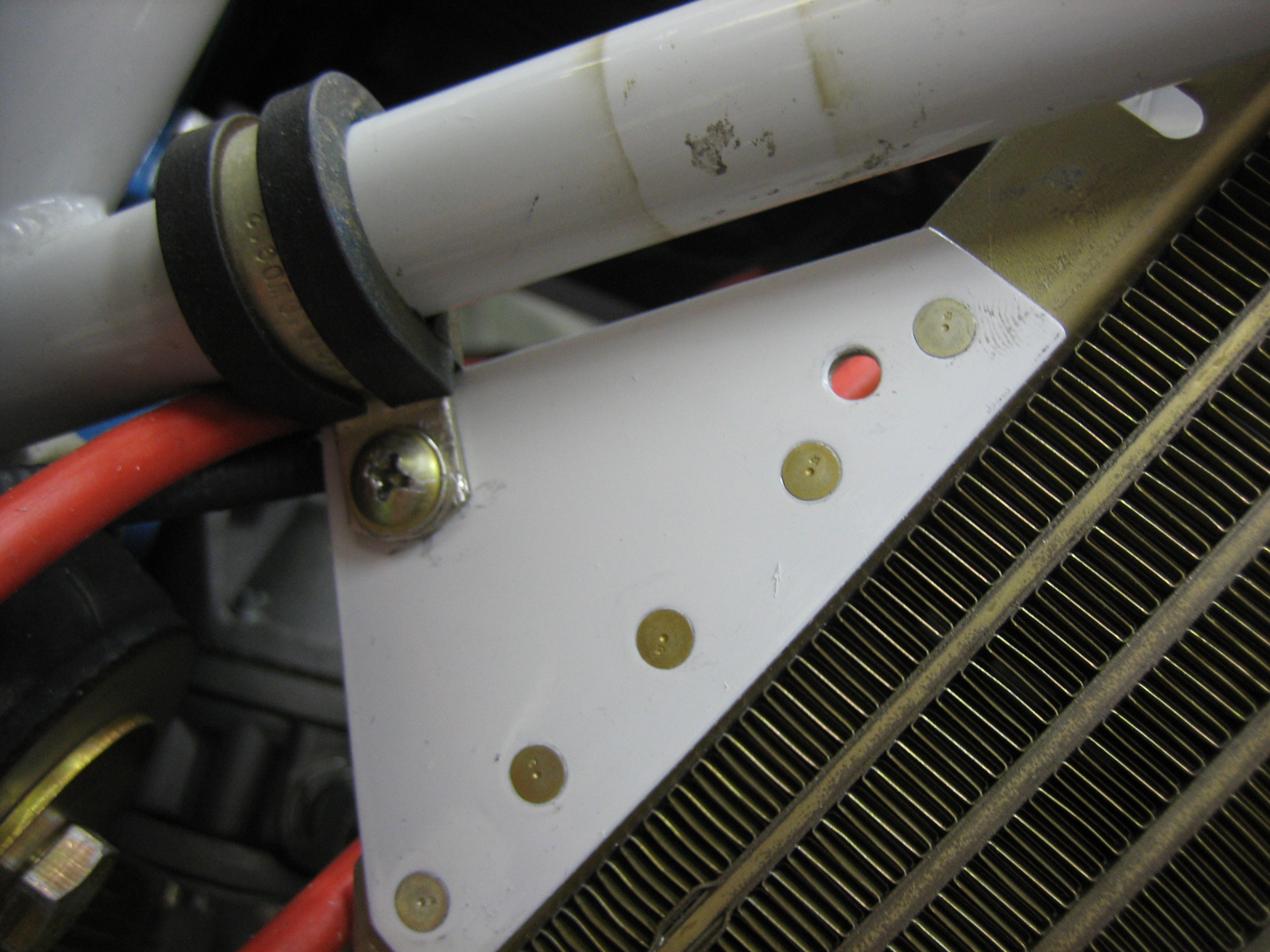
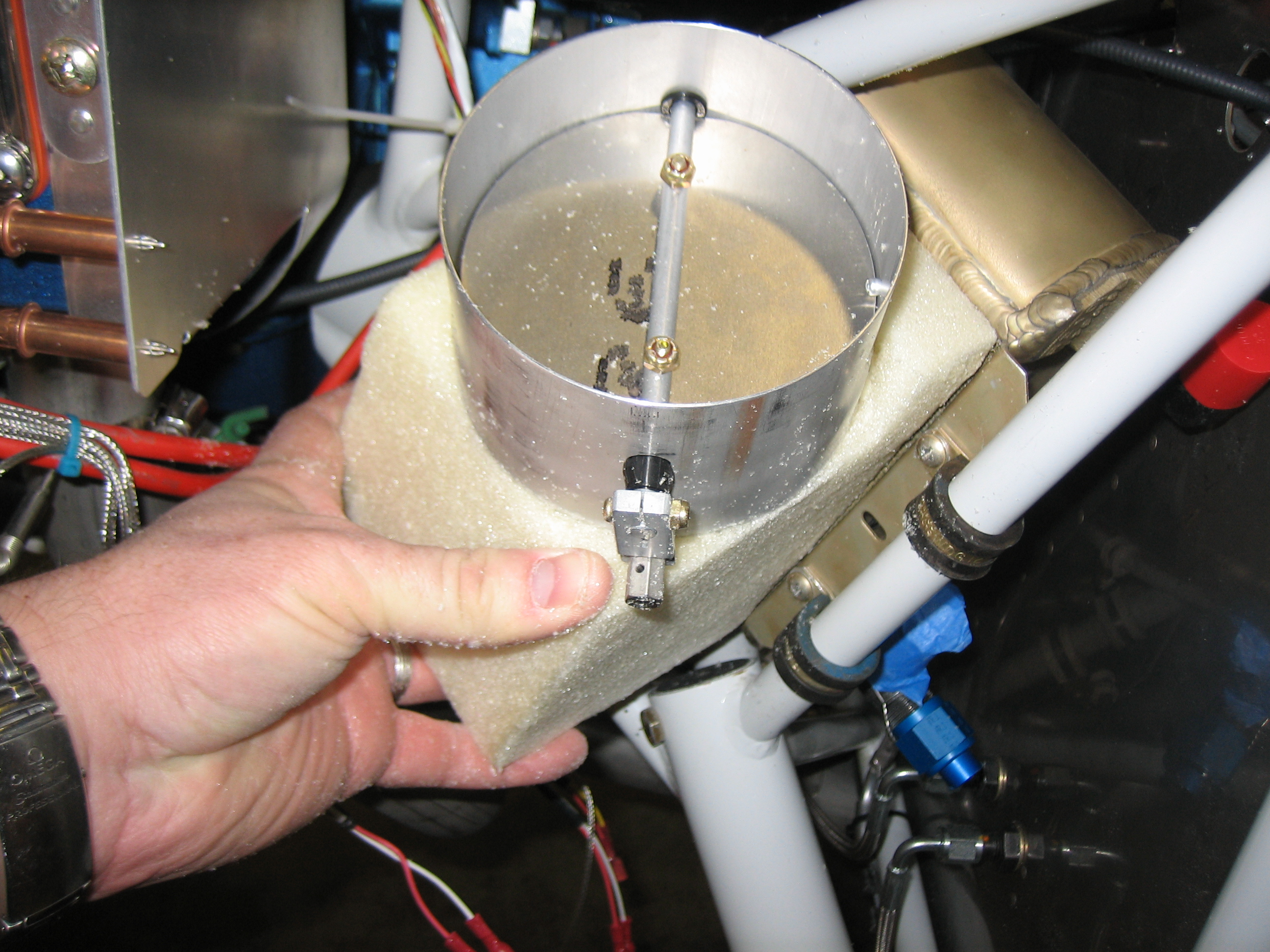
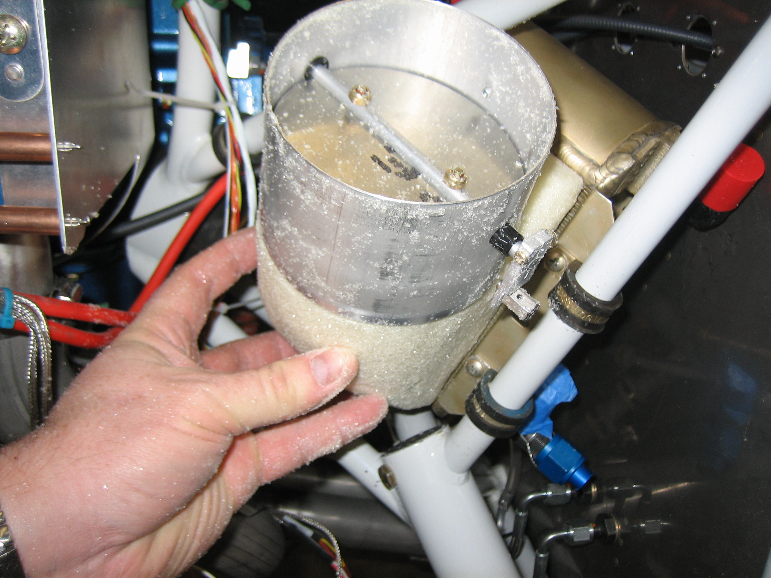
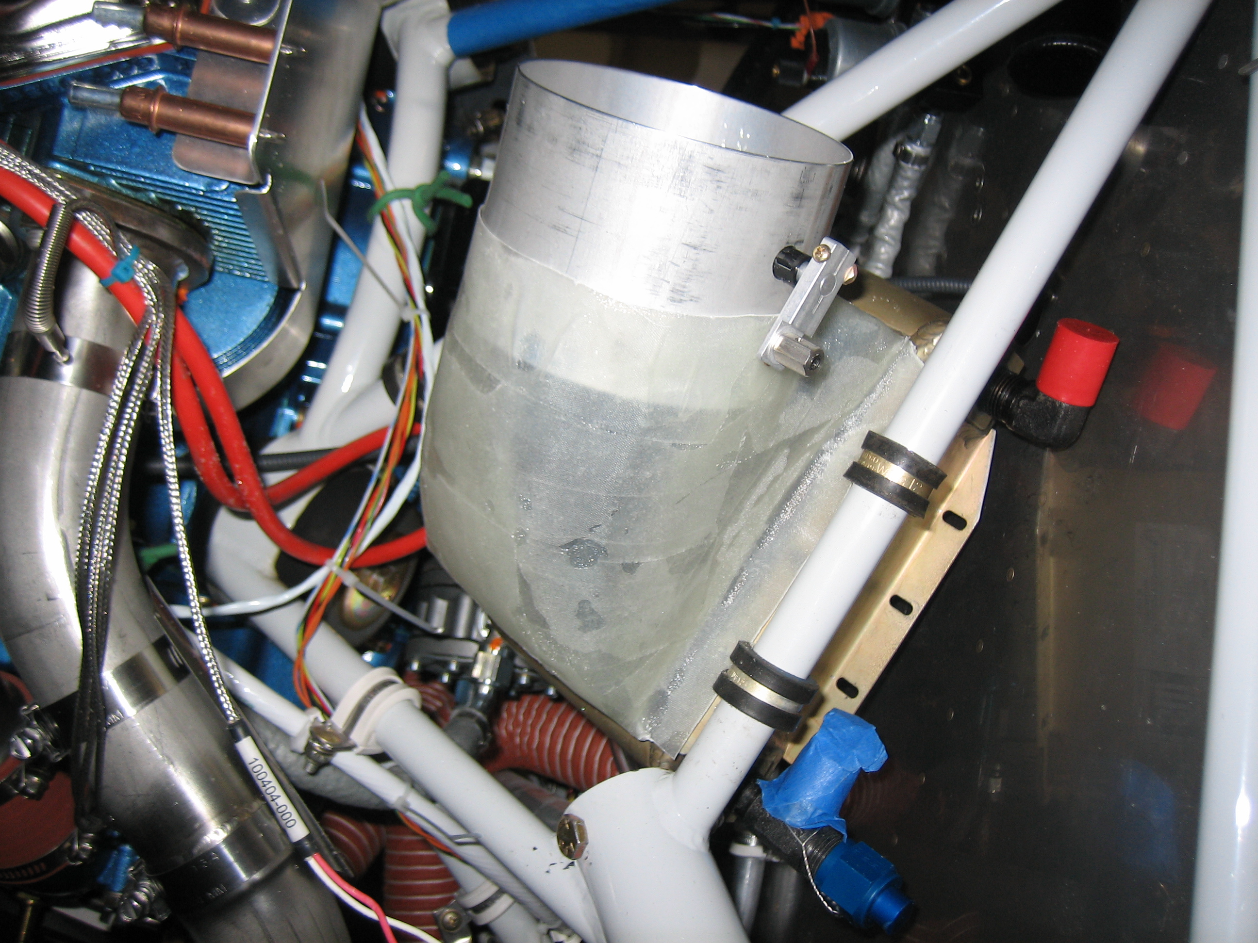
I spent the rest of the night messing around with the oil cooler position.  I think I’m finally pretty happy with the location.  I ended up turning the oil cooler over from the way I had it so that the oil cooler hoses attach on the bottom.  With the oil cooler mounted on the baffles, it’s higher than the oil return line on the engine, so oil drains out of the oil cooler automatically during oil changes.  With the oil cooler mounted on the engine mount or firewall, it’s below the oil return line, so most of 1 qt of oil would be trapped in the oil cooler during oil changes.  I did some research on this, and this is not too uncommon on certified airplanes, and the way to deal with it is to make the oil hoses enter from the bottom and put a tee in the lowest fitting.  One side of the tee will go back to the engine, and the other side will just contain a cap.  During oil changes, this cap can be removed to drain the oil out of the cooler and hoses.

More Work on the Oil Door

I drilled some extra holes in the hinges and then mixed up some epoxy and flox.  I glued and then riveted the hinge on with some soft rivets.

Next, I cut holes for a couple of Hartwell latches.  These are perfectly flush with the surface of the oil door and hold it really tight.  These needed to be mounted in this orientation because of the curvature of the oil door.

Worked on Tail Light and Oil Door

I installed a connector on the tail light along with a piece of heat shrink over the wires.  Once the rudder is installed permanently, I’ll install this on the bottom fairing and hook it up.

I decided to make a little progress on the oil door tonight.  I fabricated a spacer out of 0.063″ aluminum to pull the oil door in tighter at the hinge line.

You can see at the hinge line that the door is in nice and tight.  Without that spacer, the flexibility of the door and the force of the hinge spring was causing the door to bow out just slightly here.

Glassed Cowl Door Components

I mixed up some epoxy/flox and riveted on the oil door latches.  I then placed a couple of layers of 8 oz cloth with a 1/8″ fiber core for stiffness.  This will substantially stiffen the oil door to prevent it from bowing out in flight.  To ensure an even tighter seal, I’ve slightly flattened the oil door (that’s what the blue tape is doing).  This will ensure that when the bottom is latched, the middle of the door will be tightly pressed against the cowl.

I also put a couple of layers of fiberglass over the side of the hinge bonded to the cowl.  The top layer you see in both layups is peel-ply to wick away excess resin.

Worked on Oil Door and Oil Cooler Plenum

I took off the peel-ply and cleaned up the fiberglass a bit.  I’ll need to do a bit more work to clean this up, but it made a big difference in the door stiffness already.

I picked up some two-part expanding polyurethane foam at TAP Plastics and poured some in a box that looked about the right size to form the oil cooler plenum.  This needs 24 hours to cure before I can start shaping it.  I fully expect that this first piece will be practice, and I’ll have to make another plug before I can layup the fiberglass over it.

Worked on Oil Cooler and Fuel Overflow

I installed the fittings in the oil cooler tonight.  The top fitting is a standard AN822-8 elbow, but the bottom fitting is an AN826-8 tee with the pipe thread on the run.  You can also see that I trimmed part of the oil cooler flange to provide a little more clearance with the firewall.

Here’s a better shot of the tee fitting.  The blue tape covers the flare port that will connect to one of the oil cooler lines to the engine.  The other flare port has an AN929-8D cap that can be removed during oil changes to drain the oil from the cooler and lines.  Without this, at least a quart of oil would remain in the cooler and lines during an oil change.

I fabricated three spacers that will used when installing the oil cooler.

They will fit between the flanges (along with some washers) to allow the mounting bolts to support both the front and back sides of the oil cooler.

I fabricated a small oil cooler support plate and painted it (I’ll show a picture tomorrow).  While waiting for the paint to dry, I decided to install the fuel overflow tubing.  I used a piece of 1/4″ ID Tygon tubing to run from the AN842-4D fitting on the fuel pump down to a piece of 1/4″ tubing on the firewall.

The tubing is held on to the fitting with a piece of safety wire that is double wrapped around the tubing.

At the bottom end, I bent a short piece of 1/4″ soft aluminum tubing so that it cleared the engine mount tube and poked through a 1/4″ hole I drilled through the firewall flange and hinge.  I slipped a short piece of Tygon tubing over the aluminum tubing and zip-tied it to the engine mount.  I then used some safety wire to attach the Tygon tubing from the fuel pump to the other end of the aluminum tubing.

Worked on Oil Cooler Plenum

I riveted the additional bracket onto the oil cooler and reattached it to the engine mount.

There will be one more adel clamp and bolt when the oil cooler is installed for good.  This is just installed temporarily so that I can fabricate the plenum.

I cut down the foam block a bit more and then determined where the butterfly valve would need to be positioned.

Afterward, I did some further shaping of the foam to define the final shape of the plenum.

Here’s a better shot.  The bevel cut on the left edge allows the plenum to clear the engine mount tube.  I’ll probably tuck a small foam wedge there so that the plenum extends under the engine mount tube to allow air to flow through the entire oil cooler.

More Work on Oil Cooler Plenum

I trimmed the edges of the large aluminum area washers that surround the vent tube ports on the side of the fuselage.  I then primed and installed them

Finally, I covered the oil cooler plenum and butterfly valve with packing tape so that I can layup some fiberglass over it.  Because of the compound curves of the mold, I had to use a number of narrow strips to avoid wrinkles.

Glassed Oil Cooler Plenum

I hot-glued the form down to a couple of spacer blocks and then glassed the plenum.  I used about four layers of glass, but I only have 3oz glass on hand.  I’ll probably need to add quite a few more layers (or step up to some 9oz cloth) to make this stiff enough.  The outside is covered with peel-ply which should leave a surface ready to bond to additional layers.

Worked on Wings and Oil Cooler Plenum

I finally riveted on the flap hinge.  This has been on my to do list for weeks now, but the wings are mostly stored under a tarp beside my house, so I have to pull them around to the driveway every time I want to work on them.

I also made a little more progress on the hinges that will be used to attach the wing tips.  I taped a couple of the spacers to the hinge and then clamped it to the wing skin.

After drilling, deburring, dimpling, and countersinking, I riveted it on.  Notice that the wing side of the hinge starts with an eyelet at the trailing edge.  This is so that the hinge pin can be pre-loaded on the wing so that it’s ready to go when the wingtip is set in place.

I also pulled the oil cooler plenum out of the mold (well, mostly pulled the mold out of the oil cooler plenum) and then test fit it.  It looks like it fits pretty well, but I’ll have to do a little adjustment.  As I suspected, it’s also way too flimsy right now due to the lightweight cloth I had on hand.  I have some 9oz cloth on order.  A few more plys of that should stiffen this up nicely.

Here’s a shot down the inside.  With the butterfly valve open, the air will have a nice clean shot at the oil cooler fins.