Mounted Exhaust

Since I have the engine mounted, I decided to go ahead and mount the exhaust (mostly in an effort to get more boxes off of the floor that are taking up space.  First up, I needed to squeeze the rivets in the bottom center of the firewall where the cowl outlet sits (you can see the cowl at the bottom of the picture).  The outer portions of the bottom edge of the firewall will attach the lower edge of the cowl.

Here’s the cowl in place with all bolts torqued.  As I’ve mentioned before, I went with the Vetterman four pipe exhaust.

Here is what the exhaust looks like where it exits the cowl.  I like the look of this so much better than the crossover exhaust.  The only issue I ran into is that the four pipes stick out of the cowl slightly different amounts (over 1/2″ difference between the shortest and longest pipes).  I’ve emailed Larry Vetterman to see why this might be the case.

I went ahead and installed the oil filler neck and safety wired it to the case.

Checkoway had one of his hose clamps loosen in flight and recommended safety wiring them to prevent that.  Here, I’ve safety wired the intake tube hose clamps.

I also safety wired the hose clamps on the cylinder oil return lines.

CHT sensors and lower plugs

I didn’t have much time tonight, but I wanted to get something done on the plane.  I’m trying to get all of the fixed items installed to the engine (those where I have no choice of location) before installing those items where I do have a choice.  I used some anti-seize compound and installed the CHT sensors in the port on the bottom of each cylinder.  The wires are just hanging for now until I determine for sure where the Dynon EMS box will be mounted.

I also installed the lower plugs (again with anti-seize) since I wanted to make sure the EGT probes won’t interfere.

Battery Positive Cable, Mixture Bellcrank

I got my battery cable and terminals from SteinAir.  I’m going with #2 Tefzel cable even though it’s very hard to bend.  I considered both welding cable (recommended by Bob Nuckolls in his AeroElectric Connection book) and CCA Fatwire sold by Perihelion Designs.  Both are far more flexible, but the insulation is only good to 105ºC at best vs. Tefzel which is good to 150ºC.  It will be a little more difficult to run, and there is a slight weight penalty compared to the more common #4 wire, but this should be made up for by lower cranking wire loses which should result in a faster spinning starter and an easier to start engine.

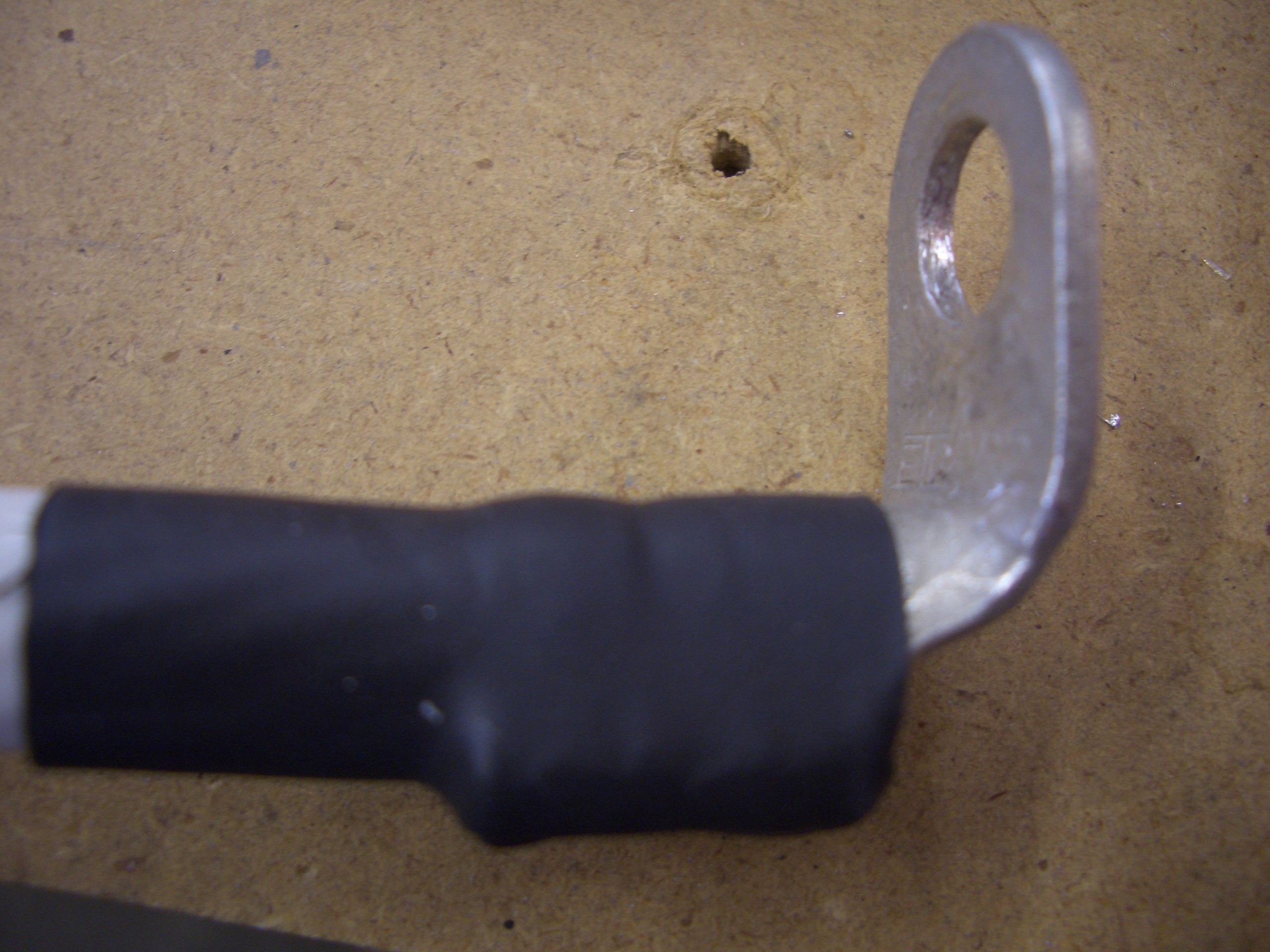
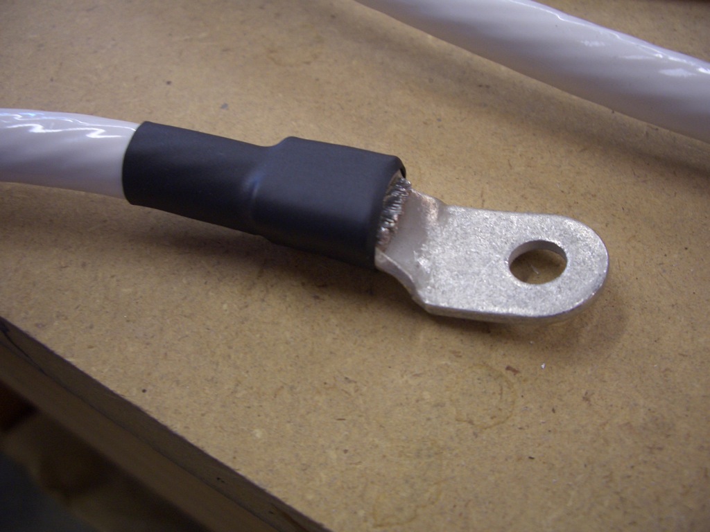
I crimped one of the connectors on a piece of wire using an impact crimper I picked up from a welding supply company.  The crimps aren’t the prettiest, but they’re very secure.

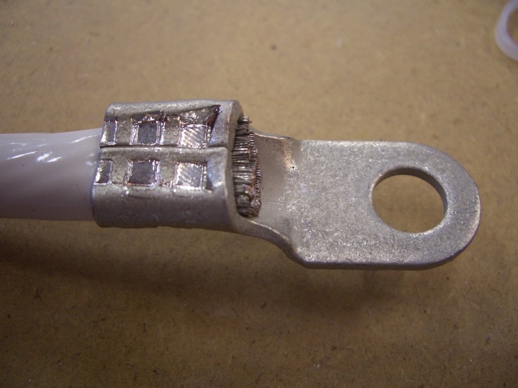
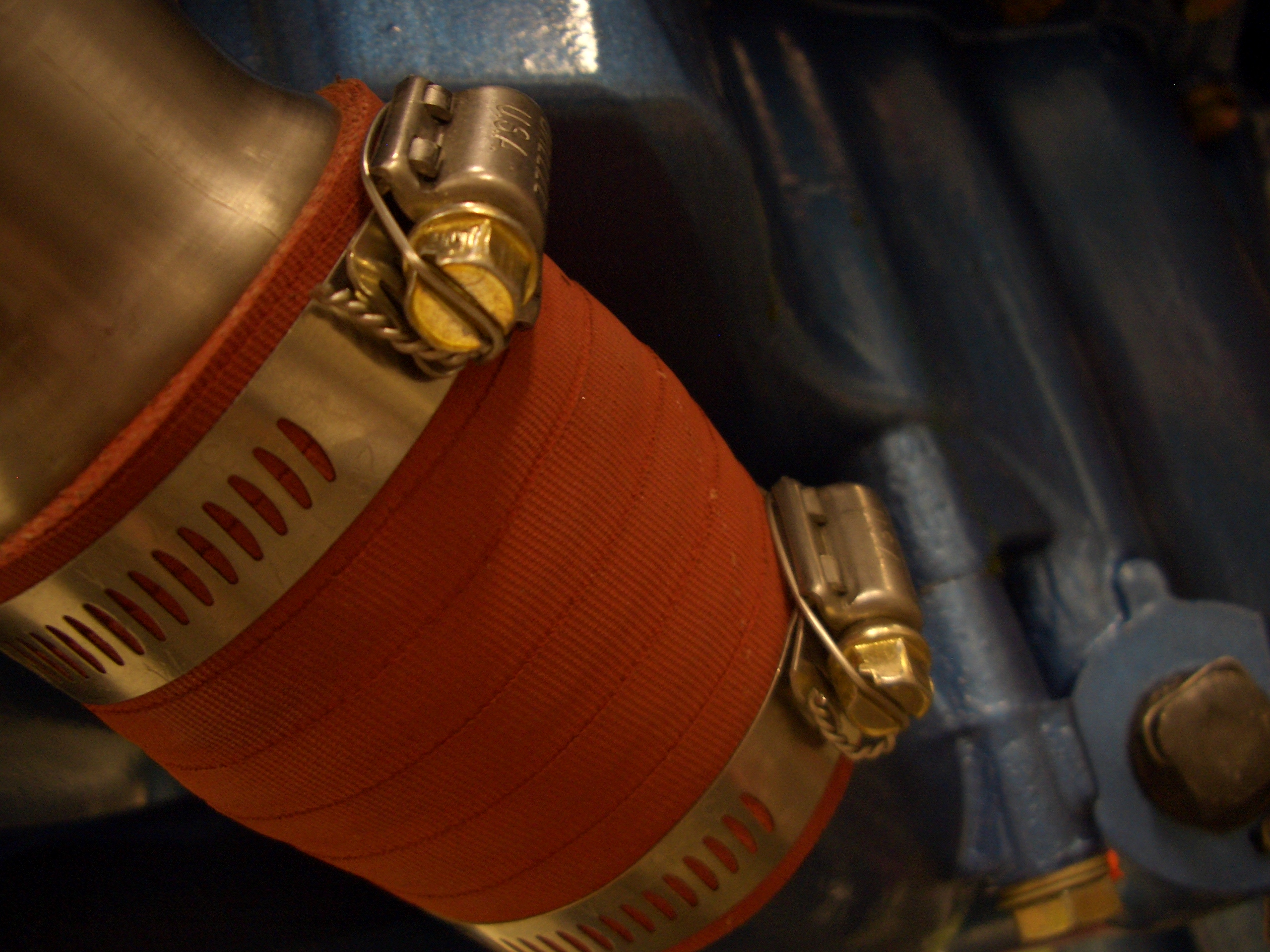
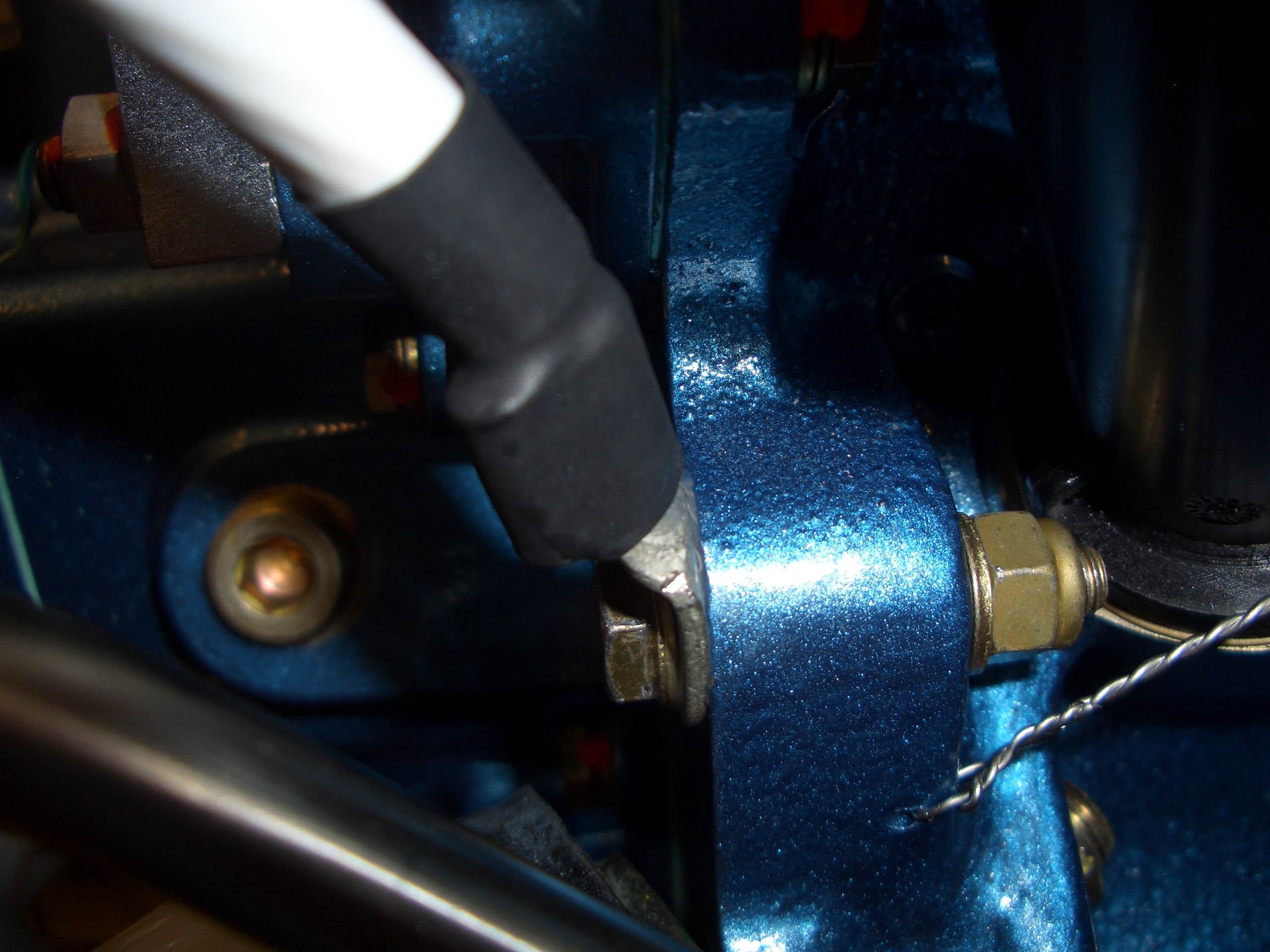
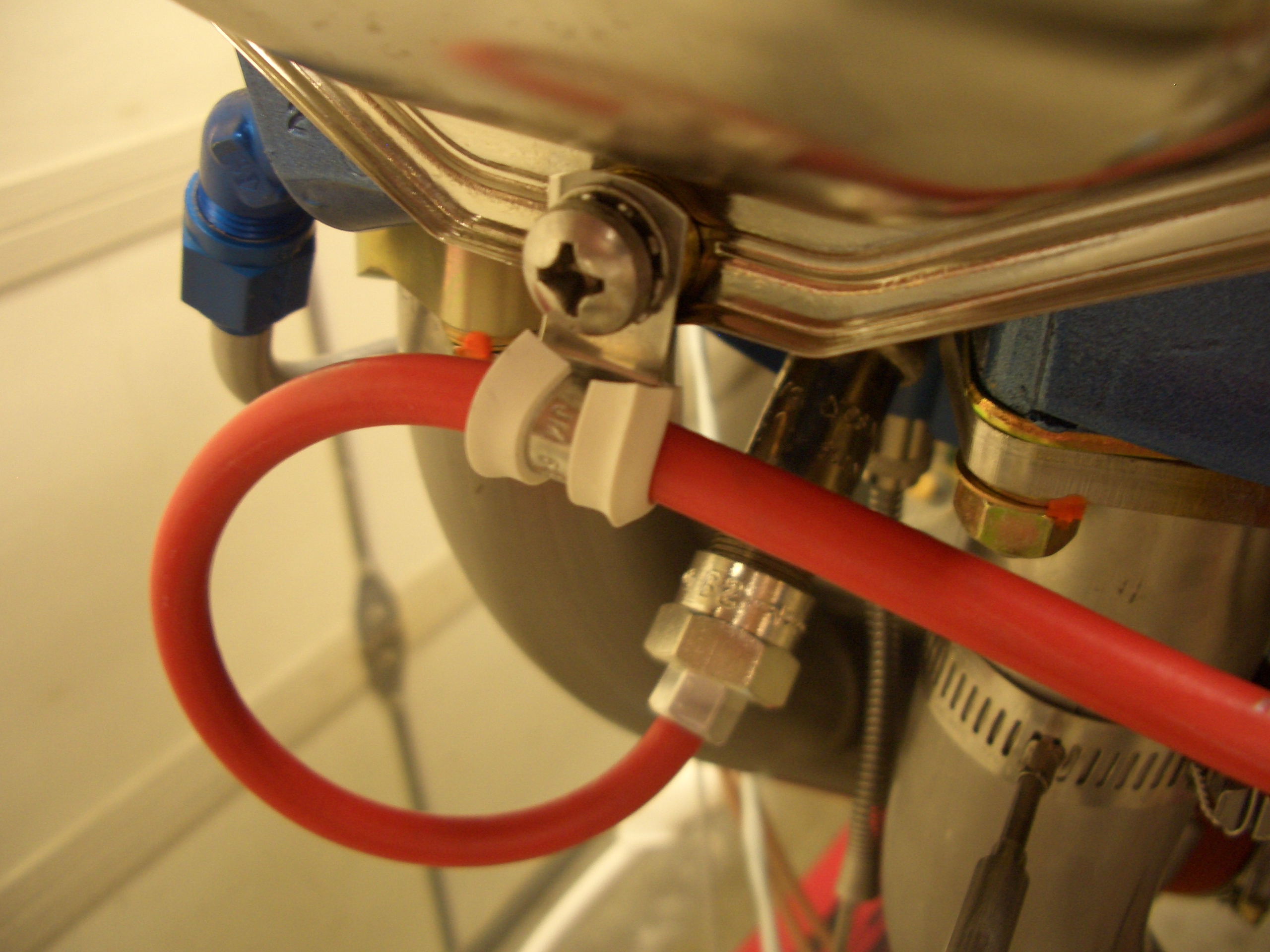
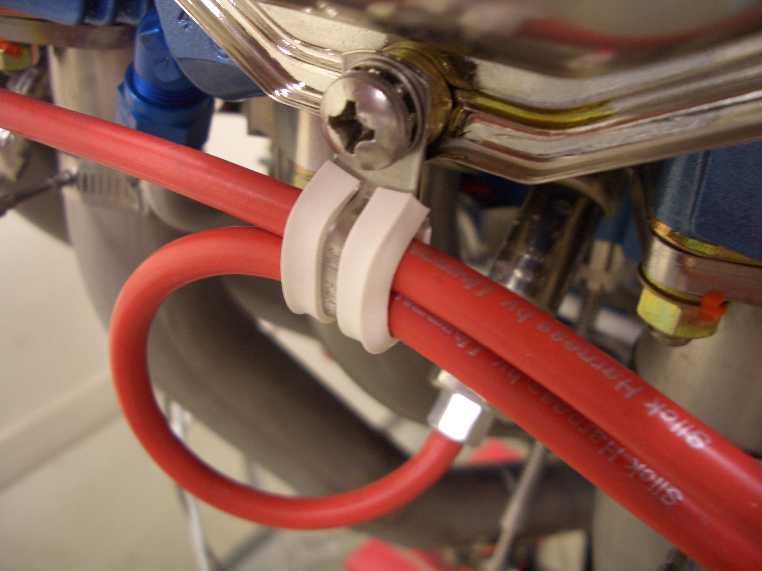
I then slipped a piece of heat-shrink tubing over the joint to provide a little bit of wire support.

I then bent the end of the terminal over 90º.

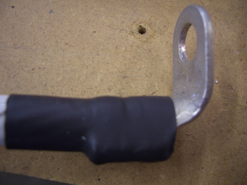
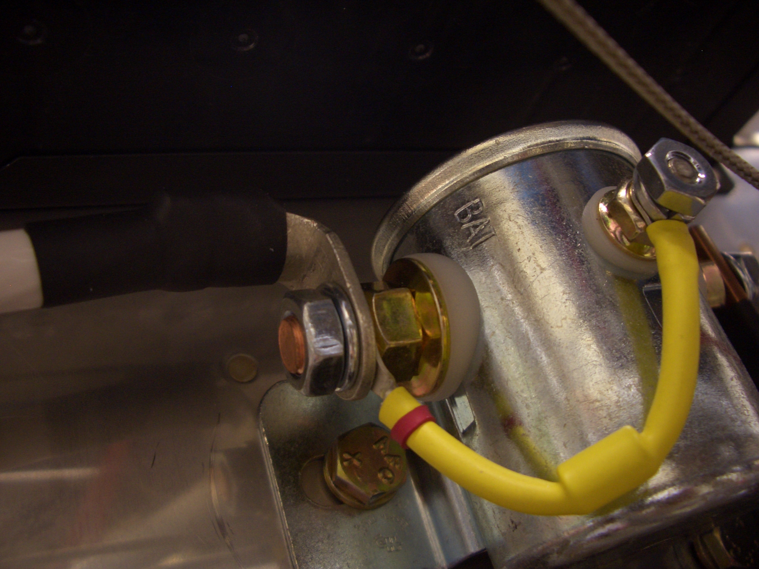
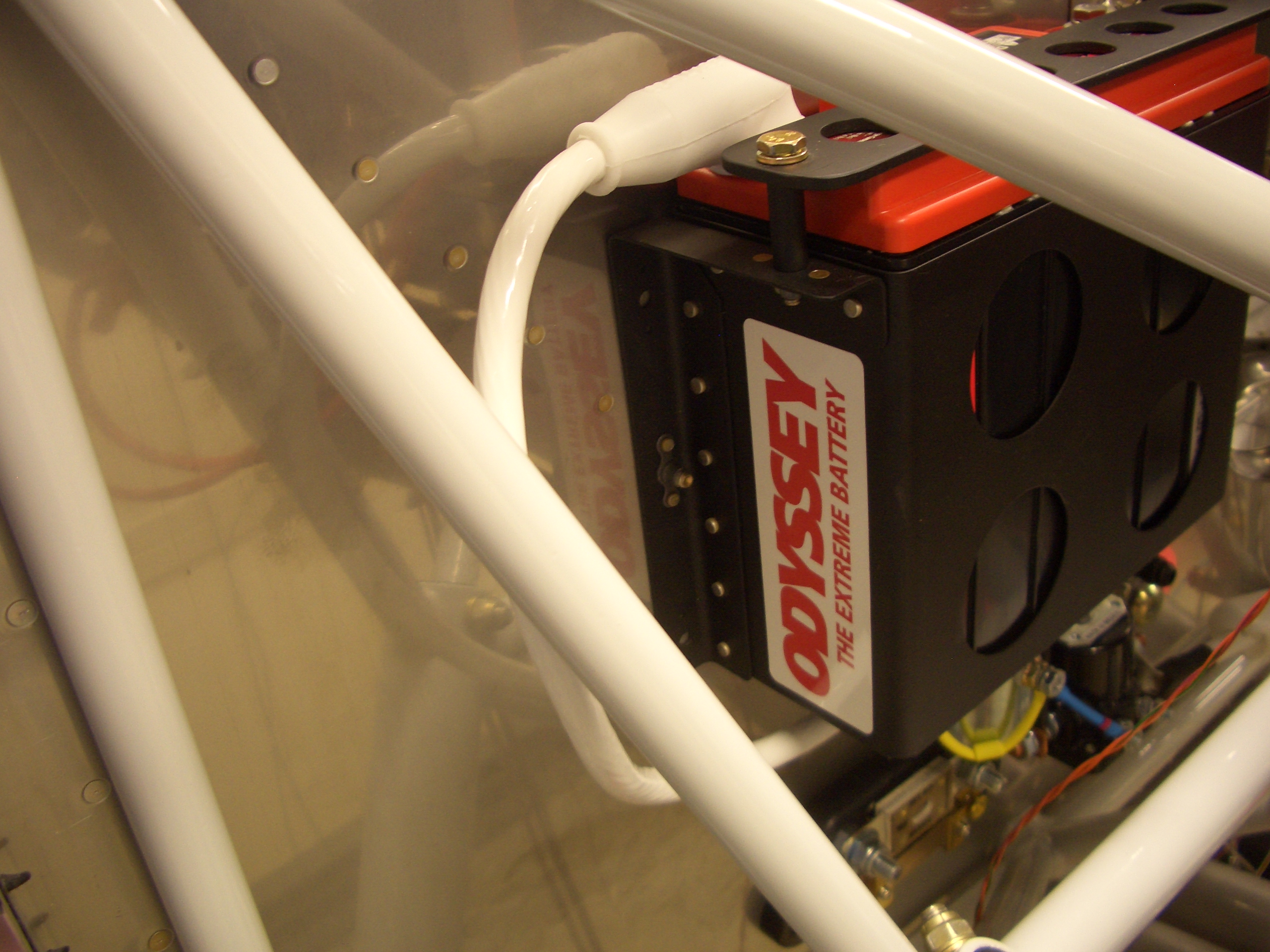
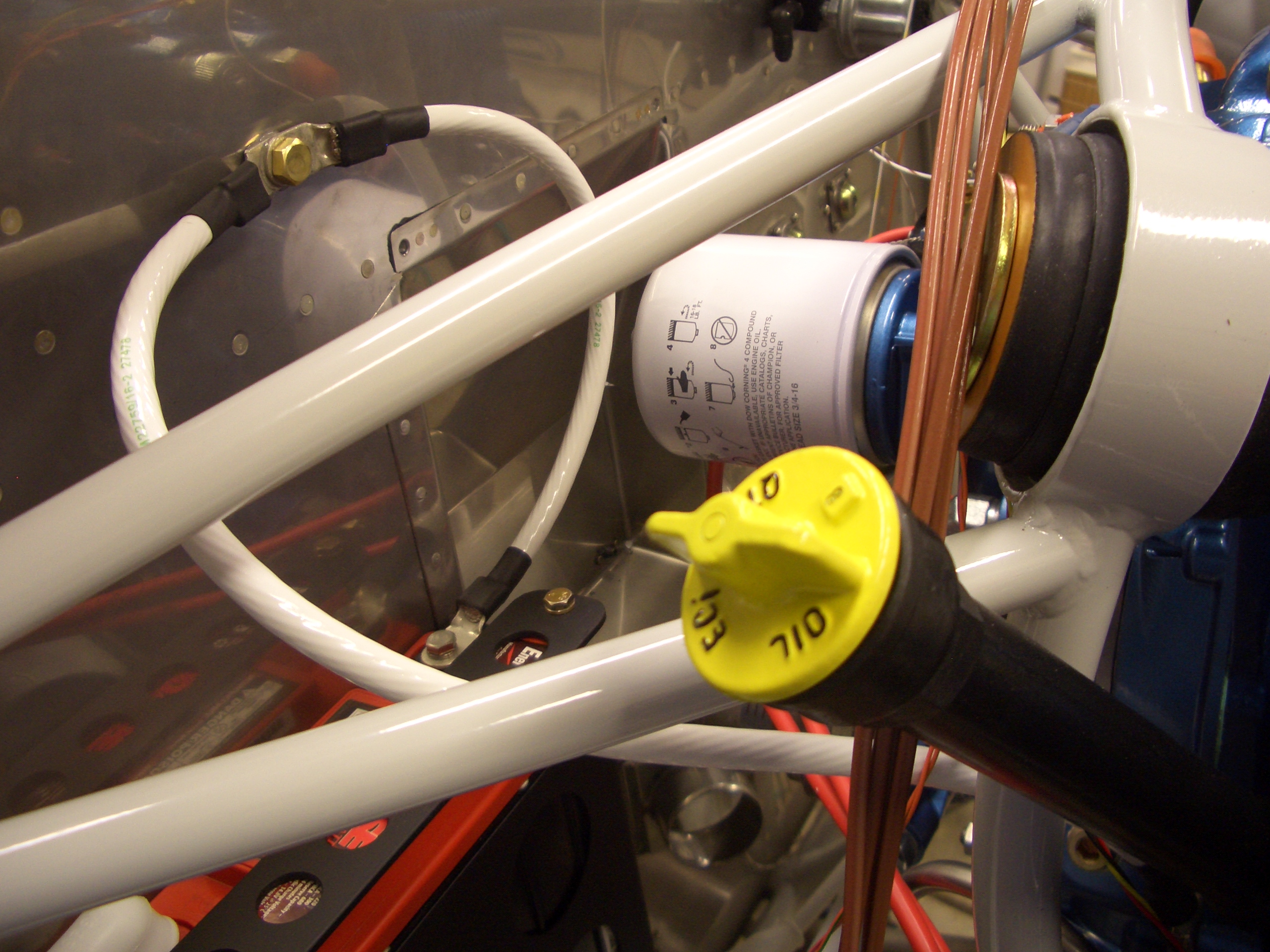
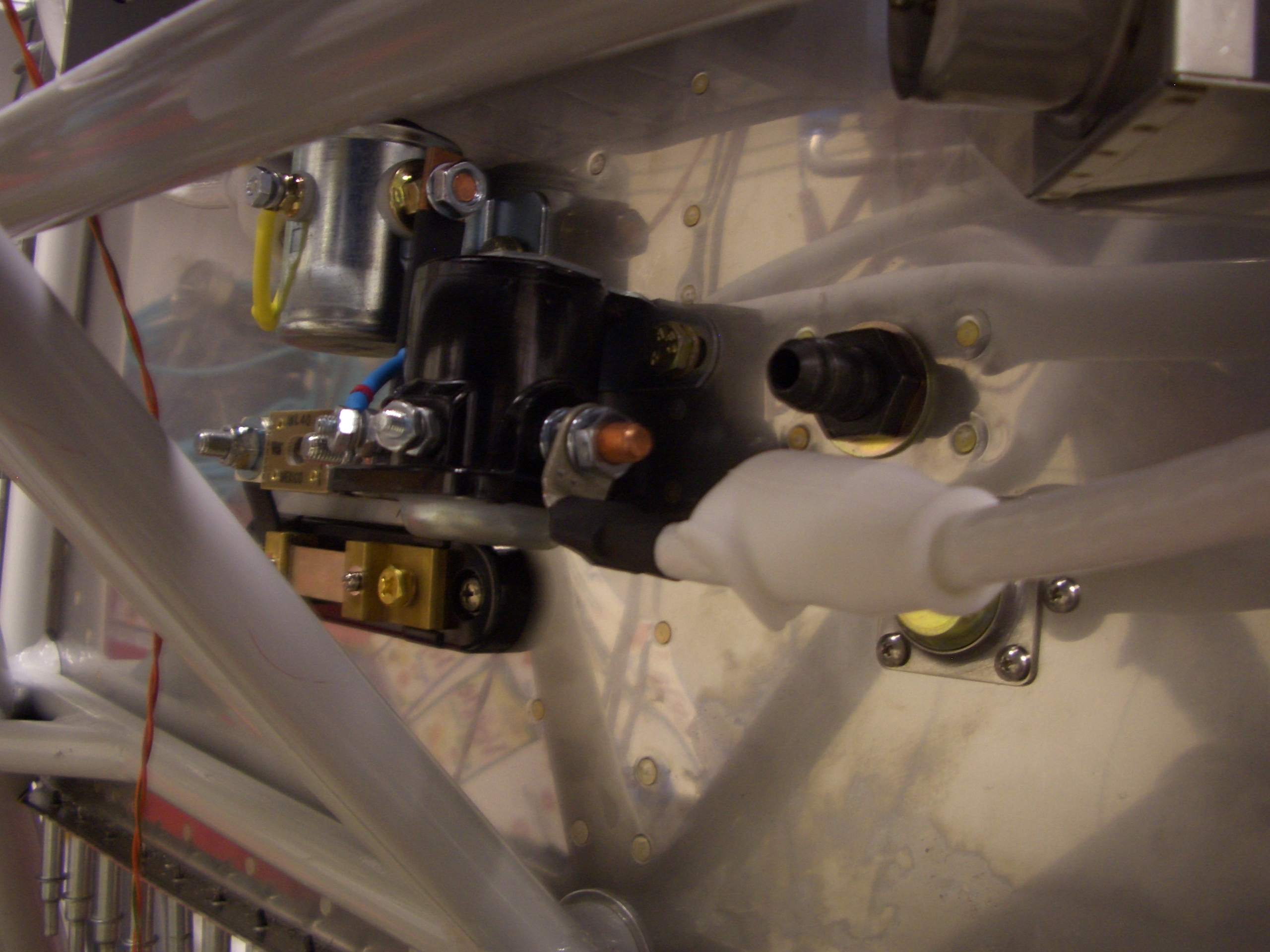
This terminal is attached to the input side of the battery contactor.  The other end will attach to the positive terminal on the battery.  I need to order so more silicone nipples before attaching the other end for good.

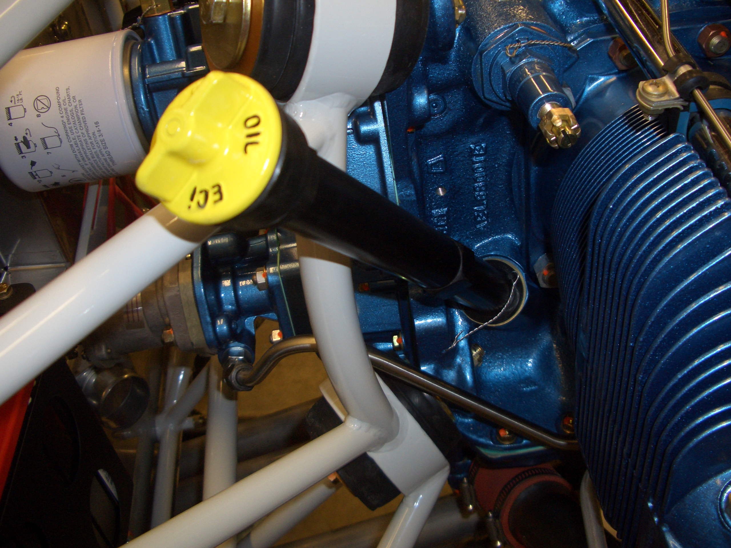
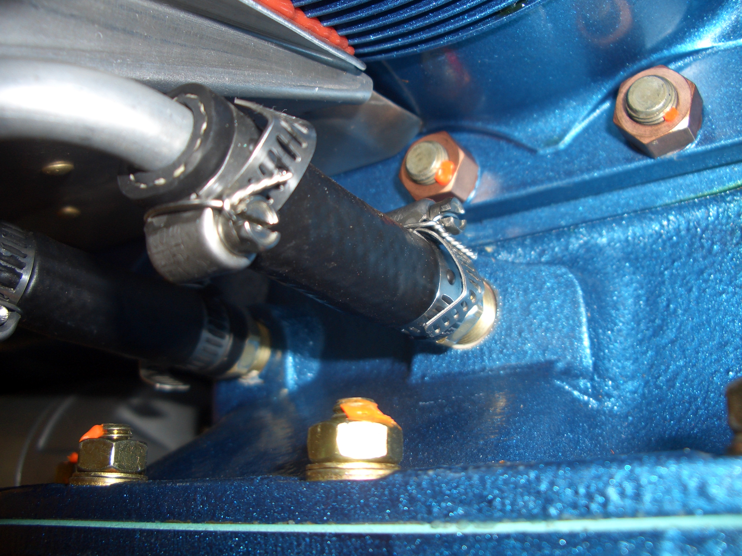
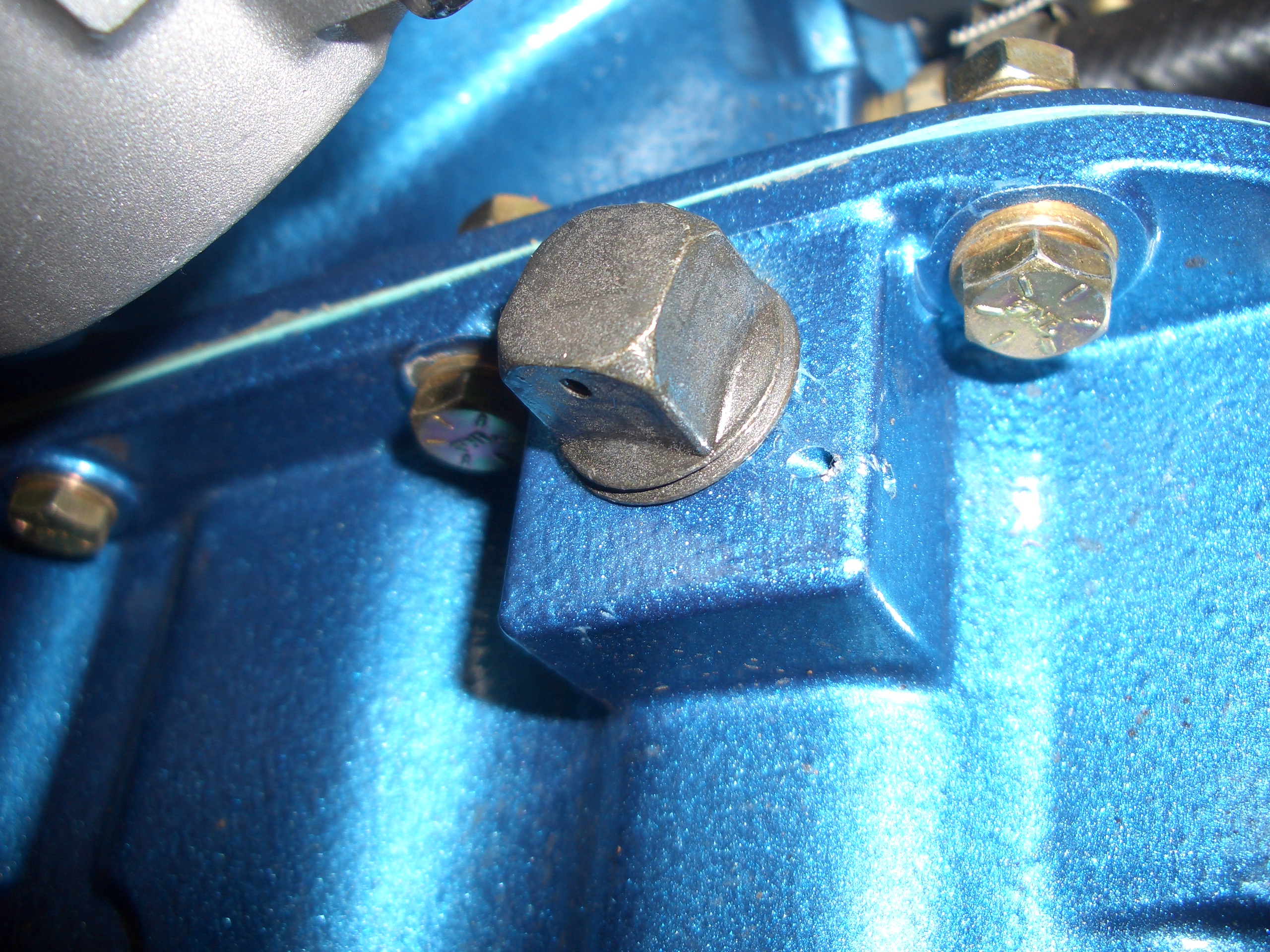
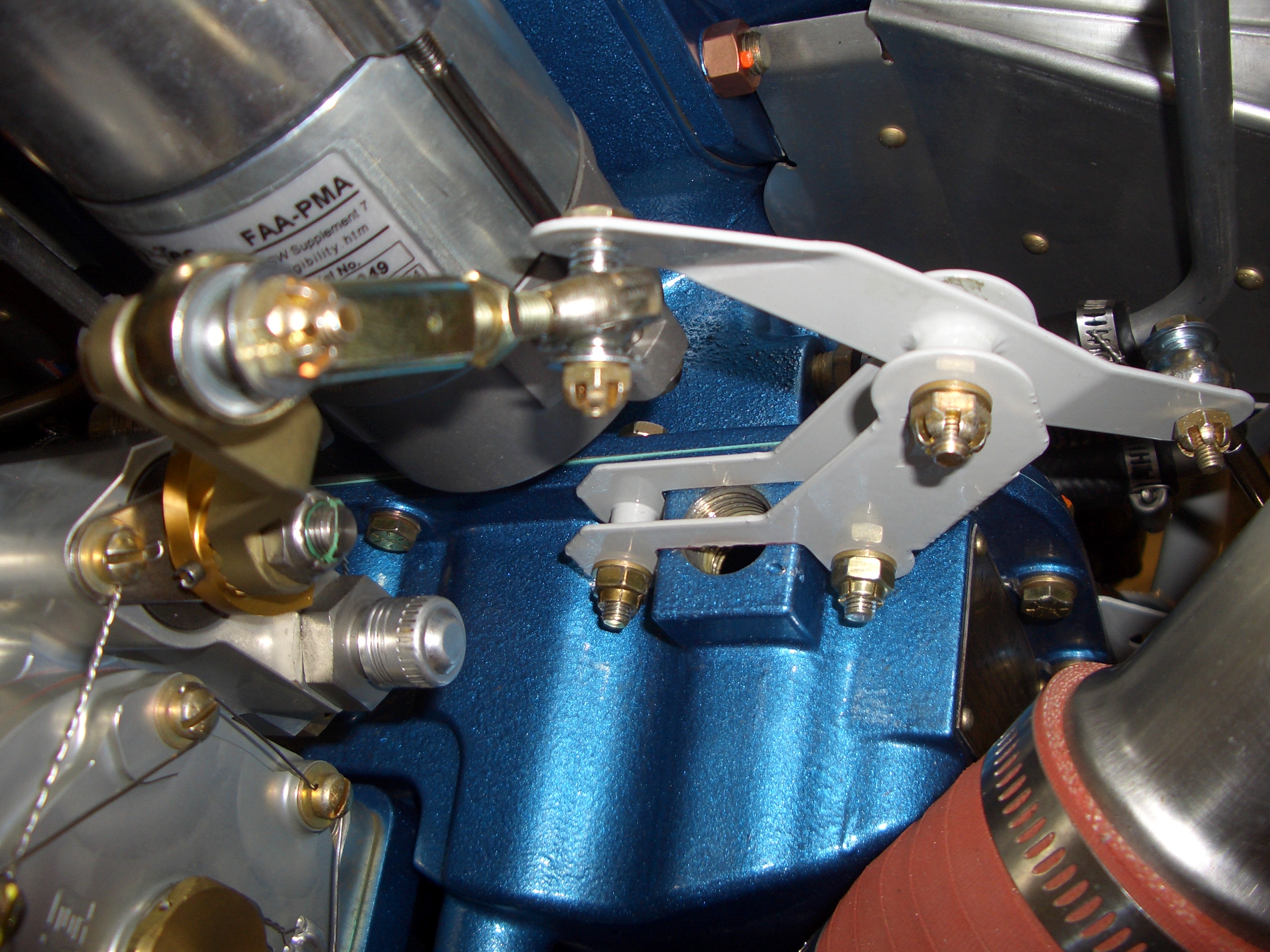
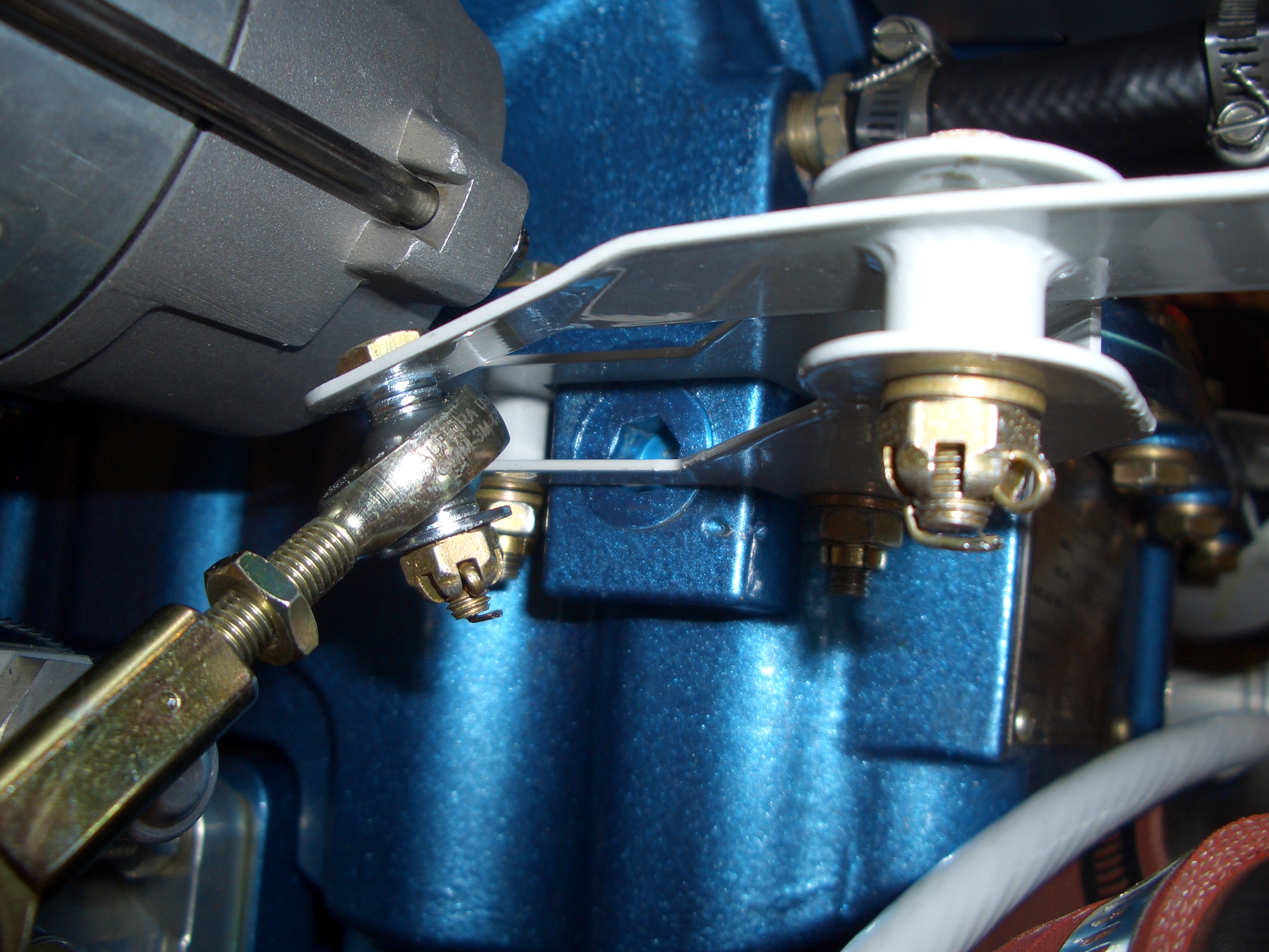
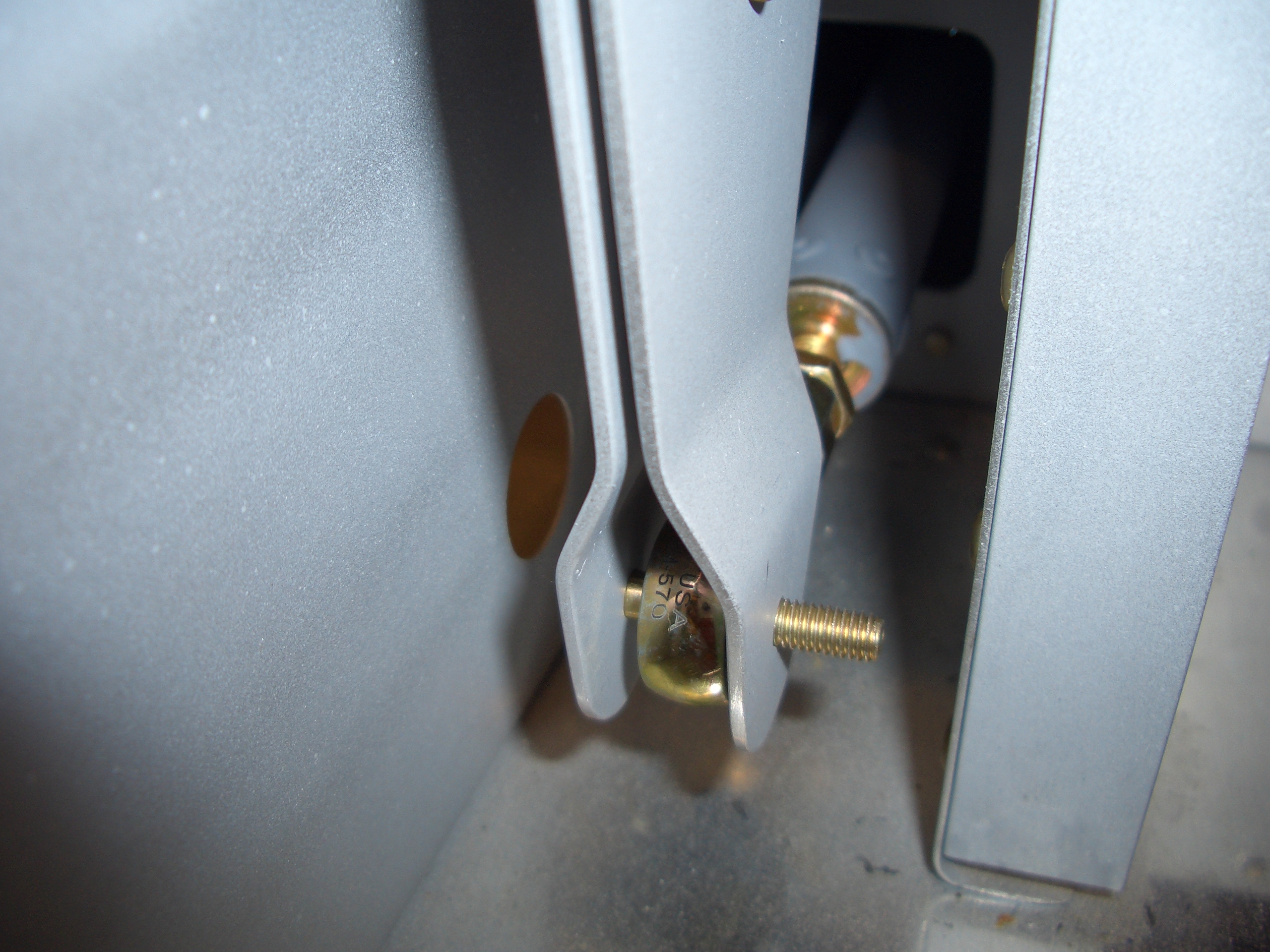
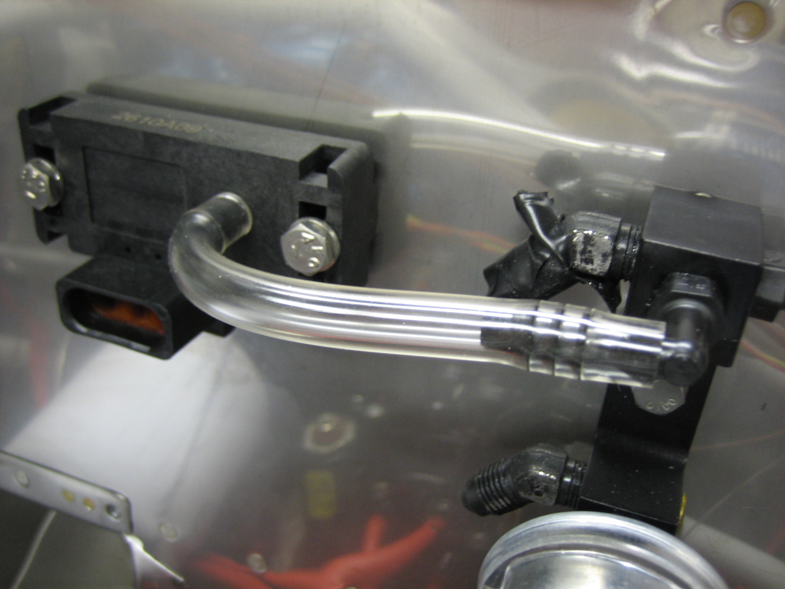
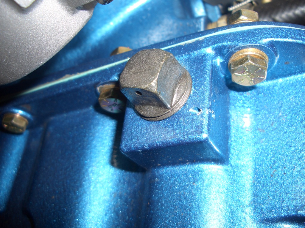
I wanted to see if the mixture bellcrank would fit on the superior sump.  It’s supposed to install under these two bolts, but this plug is in the way.

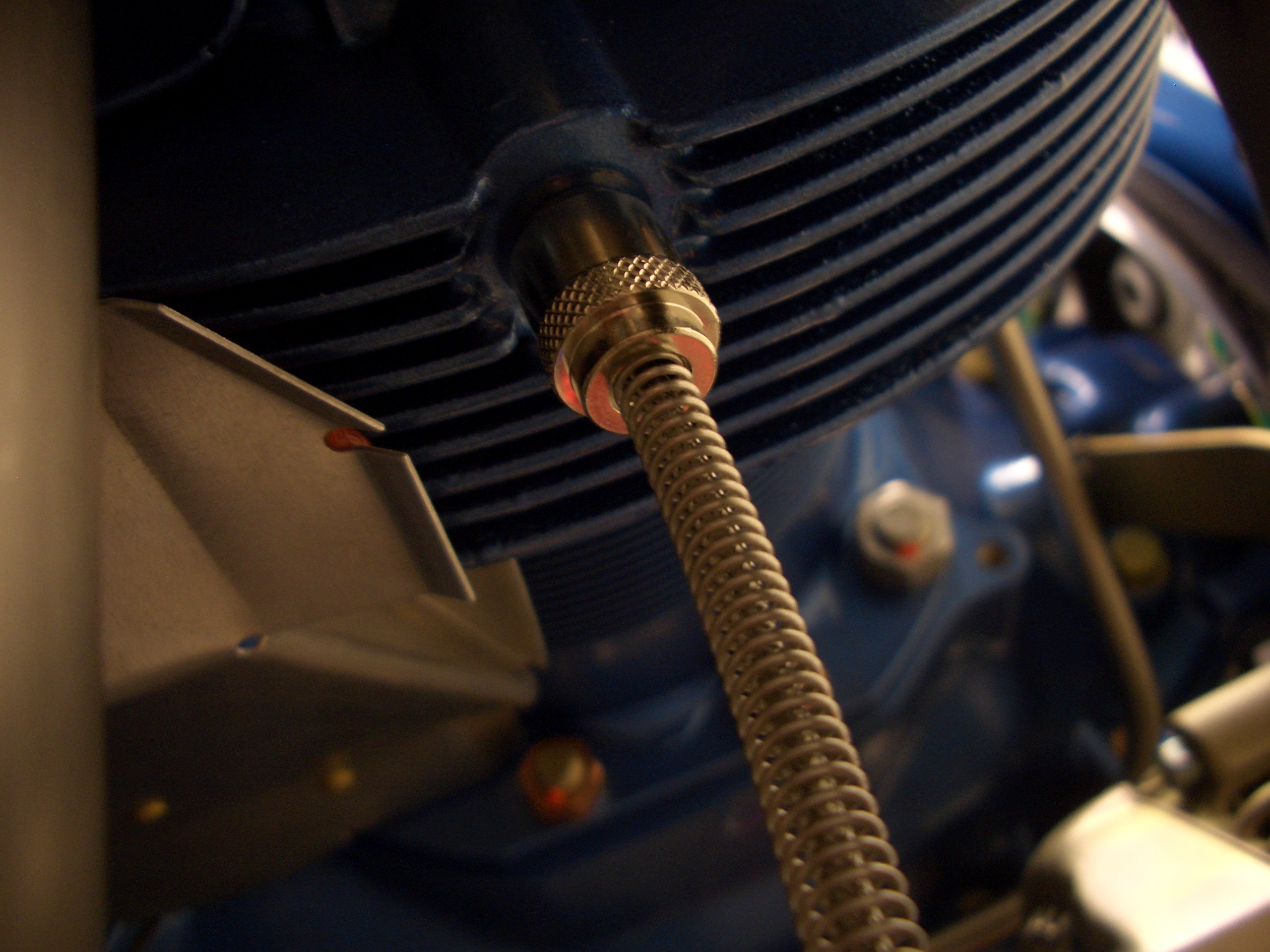
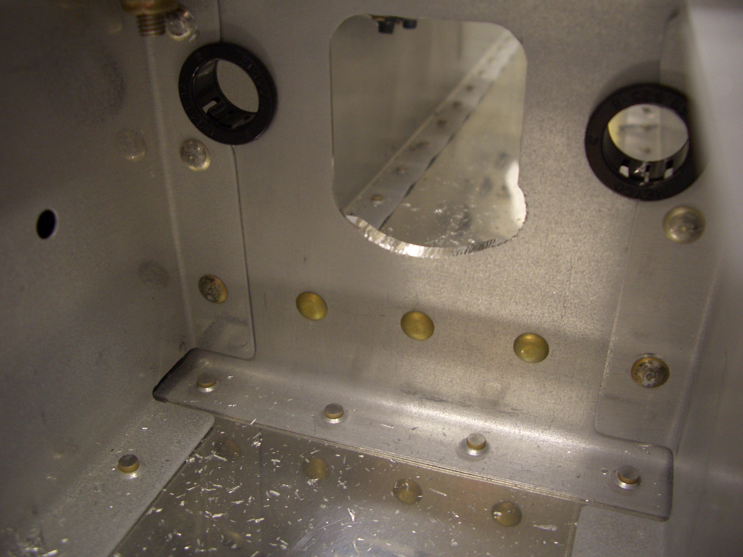
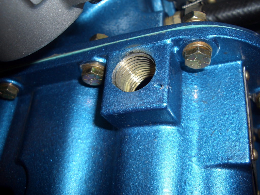
After cutting the safety wire and removing the plug, here’s the hole that’s left.

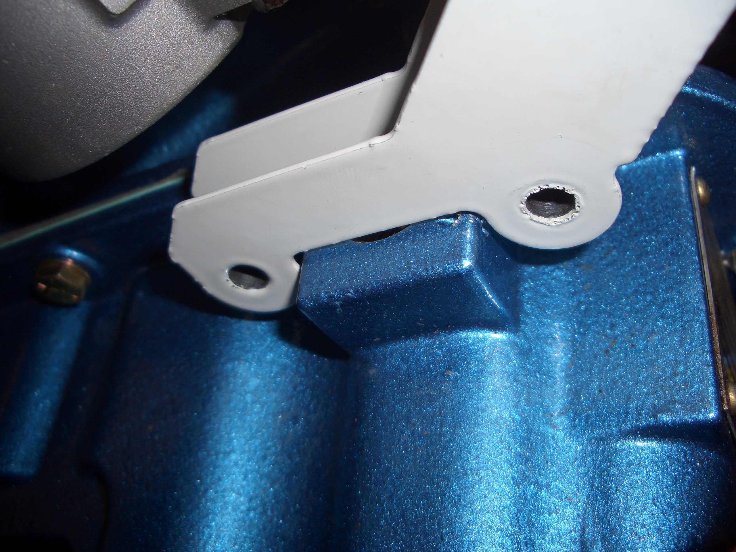
The bracket now fits over the boss in the sump, but unfortunately the holes are still off by almost 1/4″

I deepened the notch in the bracket enough that it could be bolted in place.  Notice that the hole is still there, and this bracket will prevent the original plug from being reinstalled.  I’ll have to order an AN932-5 plug to install here instead.  That is a hex drive plug that will install flush with the surface of the case.

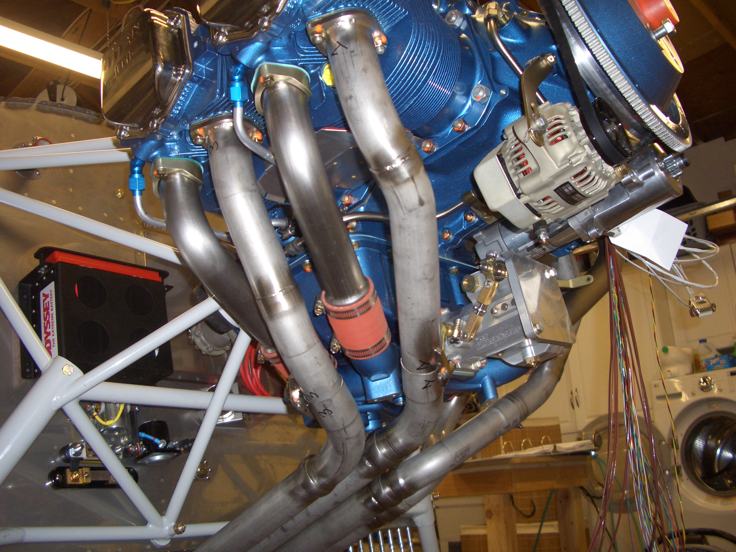
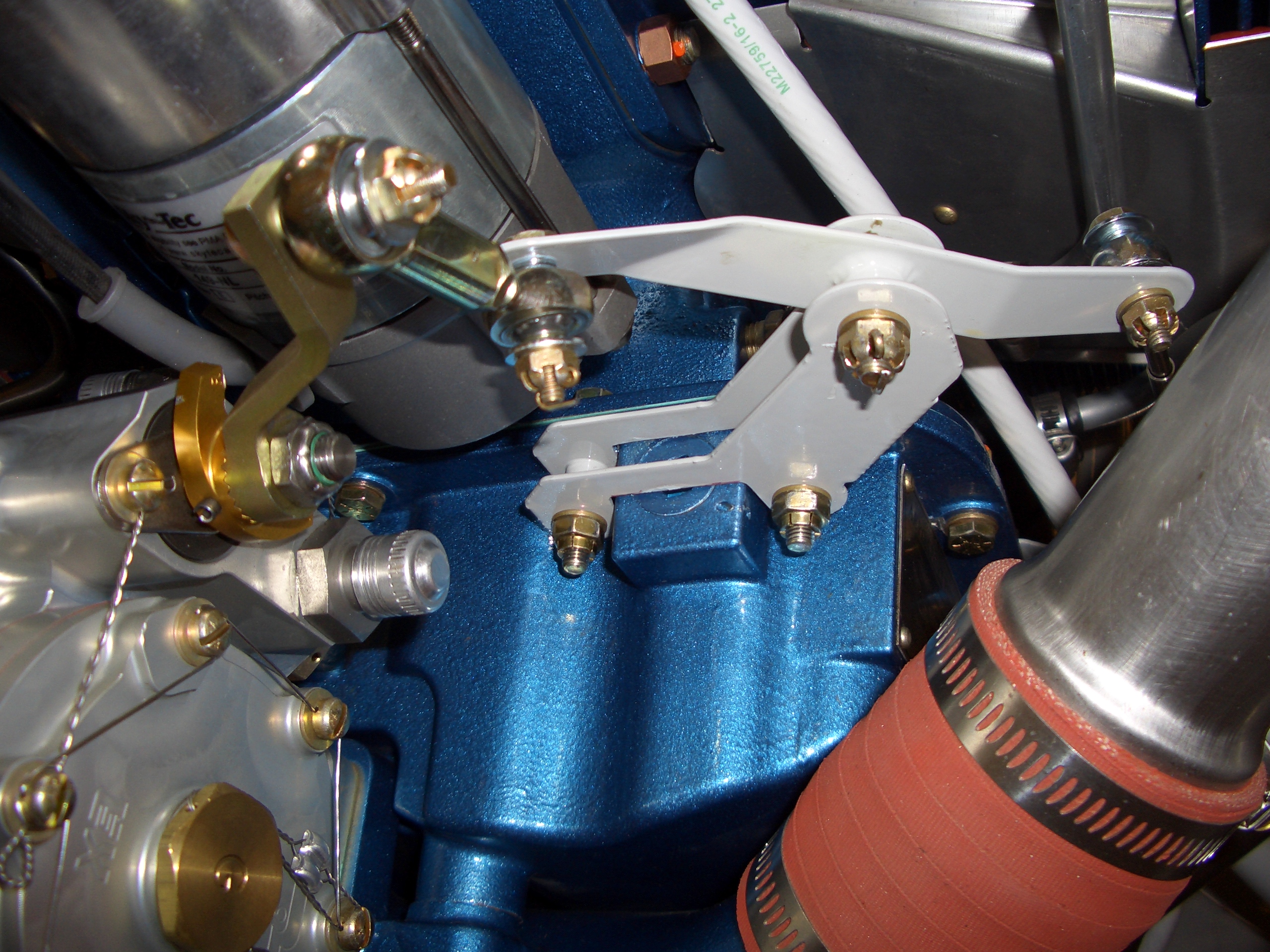
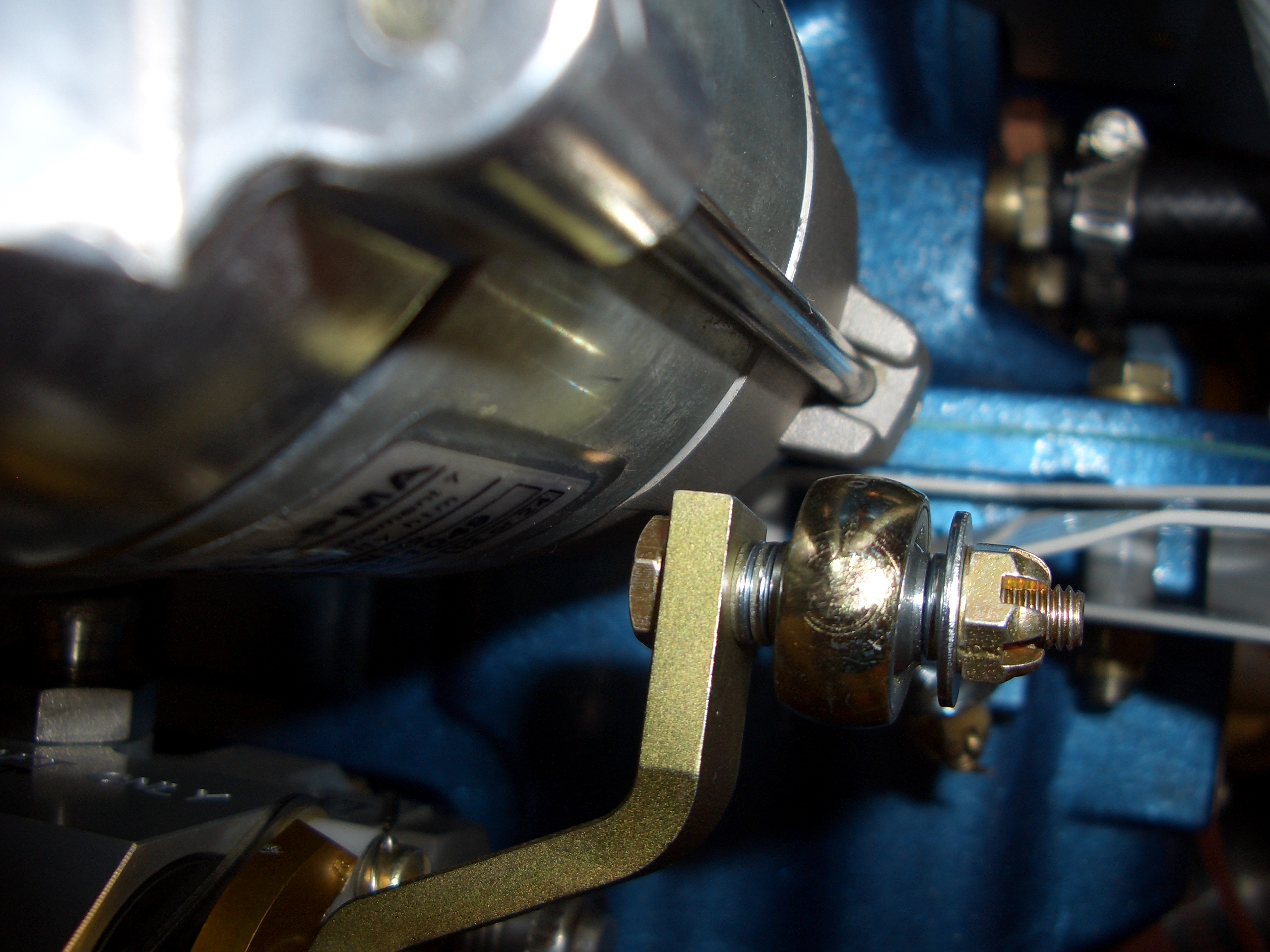
Here is the mixture bellcrank in the most rich setting I can get.  Unfortunately, the mixture lever is interfering with the starter.  I’ll call Precision Airmotive to see if they can send me an alternate mixture lever.

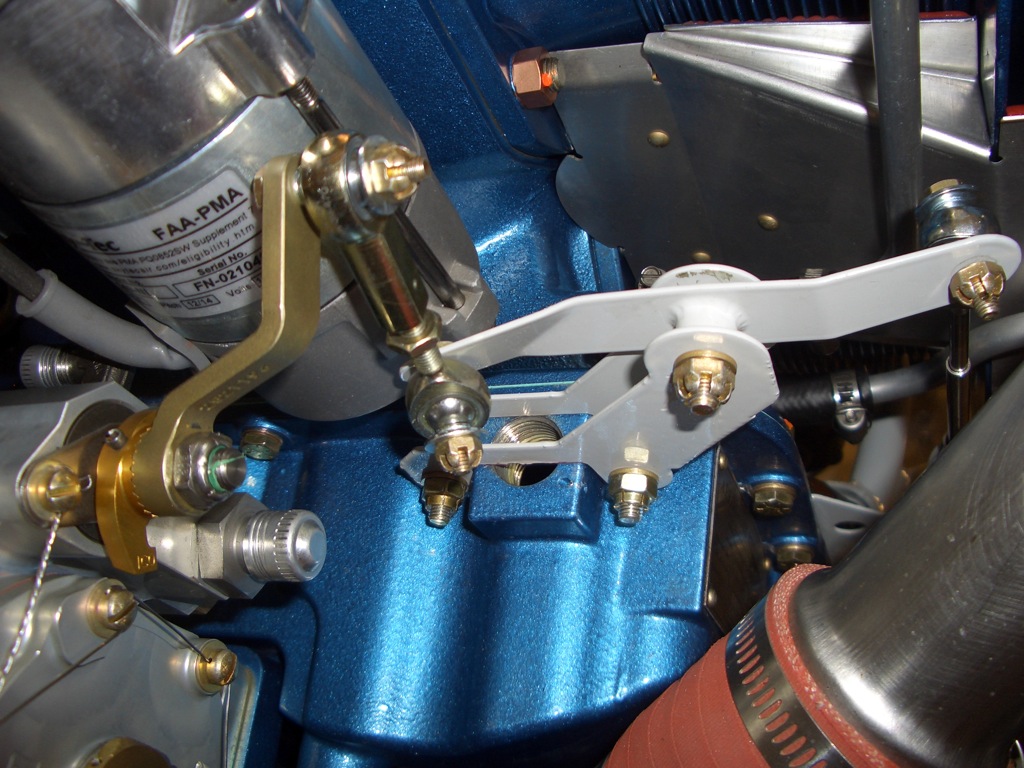
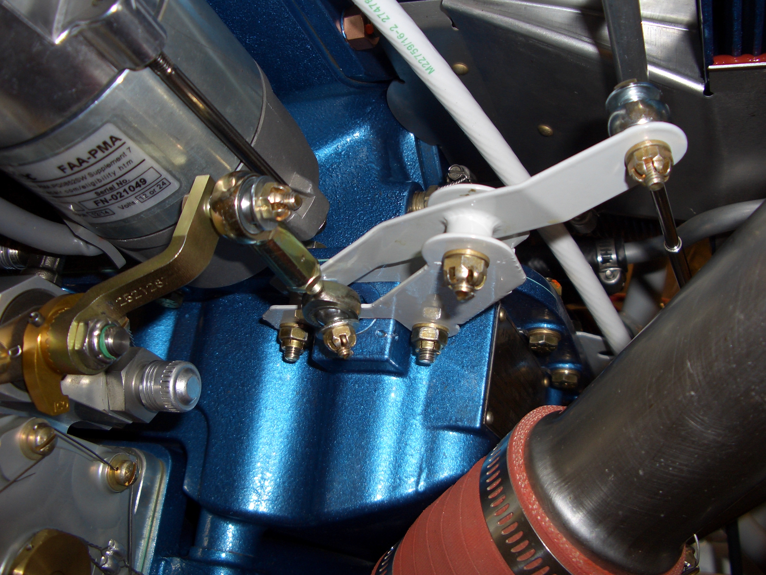
Here is the mixture bellcrank in the most lean position.  I can hit the idle cutoff stop without any problems.

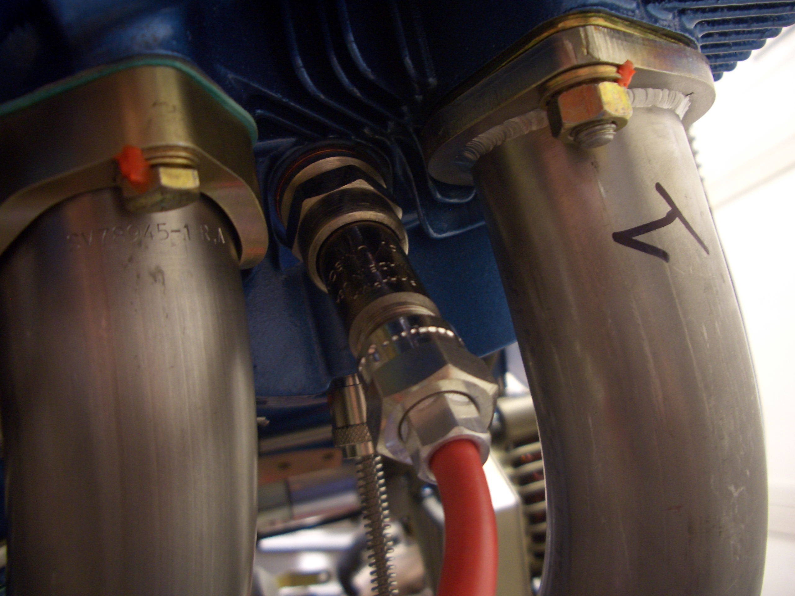
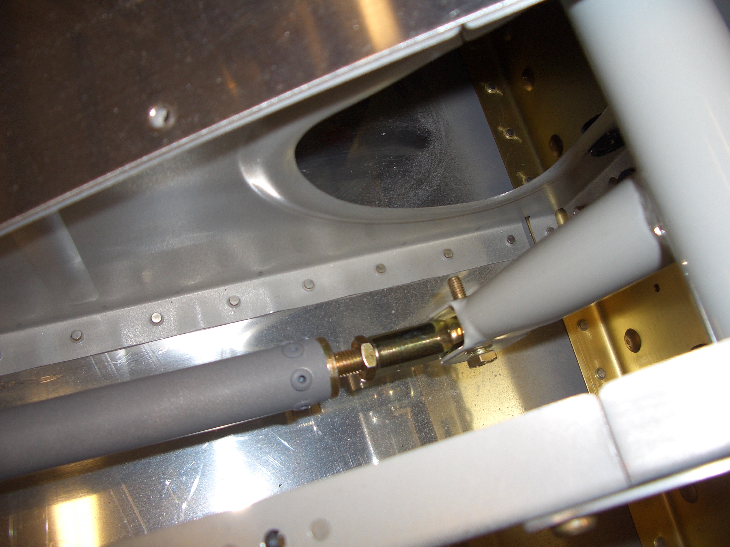
Finally, I spent a little time trying to figure out how to secure the throttle cable.  The Superior sump doesn’t have threaded ports in the bottom in the same location as a standard Lycoming sump, so the bracket from Van’s won’t fit.  I’ll probably have to fabricate a custom steel bracket for the throttle cable.

Swapped Rocker Cover Gaskets

I called Precision Airmotive this morning, and they have a shorter offset mixture arm (1 5/8″ vs. 2″) that should work perfectly for me.  This should eliminate the interference with the starter and allow me to hit both stops on the mixture arm.  With the longer lever, I could hit one stop or the other, but not both due to the short throw of the control cables.

I also called around for a bit trying to find an AN932-5 plug, but couldn’t find anybody who stocked them.  I ended up ordering an AN932-5D plug instead which will work fine.

I spent most of the night cleaning up the garage, but I did swap out the rocker arm cover gaskets.  You can see the old cork gasket on the left and the new silicone gasket on the right.  Surprisingly, I already found an oil leak from the old cork gasket, so I’m glad I replaced these.

Firewall Forward Wiring

I finished the battery positive cable.  There will be a couple of adel clamps securing this to the adjacent engine mount tube to prevent the terminals from carrying the full weight of the cable.

I also fabricated the engine ground strap.  I used an empty hole near the oil filler neck which required removing all of the paint on the aft side of the boss.

Here is how the cable routes up to the grounding strap.  You can also see the battery negative cable here.  I can still easily remove the battery without having to loosen any cables.

I also put the fitting on one end of the starter cable.  I left the starter cable a little long since I’m not 100% sure of the routing right now.  It needs to pass through the same area as the mixture cable and bellcrank, so I want to have that in place before finalizing the routing.  You can also see in this shot that I added a washer under the fuel fitting.

I moved the 45º fitting up to the top port in the pressure transducer manifold and installed a 90º fitting in the bottom one for the fuel pressure hose.  I also installed a couple of polyethylene hose fittings in the top port.  One will route manifold pressure to the Dynon MAP sensor just to the left and the other will route manifold pressure to the Lightspeed electronic ignition.

I also spent a little more time playing with the locations of the various boxes that will mount forward of the subpanel and I think I came up with a layout that I like.  Here is where the Dynon EMS box will mount.  I separated the sensor wires from the 37 pin connector into one bundle that needs to penetrate the firewall and one that doesn’t.

Here is where I’m planning on mounting the Lightspeed ignition box.  This provides convenient routing of the primary ignition wires which will run alongside the battery and main bus power lines.

And here is where I’m thinking of installing the voltage regulator.  I can still easily reach the voltage adjustment screw in this position.  The only disadvantage is that I need to drill a few more holes in the firewall.

Installed Exhaust Gas Temperature Probes

I installed my EGT probes tonight.  Dynon recommends 2-8″ from the exhaust flange.  The precise distance isn’t important, but it’s very important that the distances are the same for each cylinder since that lets you compare EGT readings across cylinders.  Anything over 2″ on my exhaust setup would put the probes past the first bends, and it would be hard to remain accurate on the measurements.  These constraints pretty much dictated that my EGT probes would be at exactly 2″ from the exhaust flange.  I positioned the probes so that they stick straight out from the sides of the pipes.  I’ve seen a lot of builders angle these one way or the other to try and keep them from sticking out so far, but there is plenty of clearance from the cowl sides and this keeps them from interfering with other things like the lower spark plugs.

Here’s a closeup of the #2 probe.  Just like other hose clamps in the engine compartment, I safety wired them to prevent them from ever backing off.

Installed Sump Plug and Mixture Bellcrank

I received my AN932-5D plug from General Aircraft Hardware.  $17 bucks shipped was kind of a ripoff, but the alternatives would have been even more expensive.  I had to grind off about 3/64″ from the visible face here to get the surface flush with the sump.  After installing it, I used the touch-up paint that came with my engine to paint the exposed aluminum face to match the engine.  I then installed the mixture bellcrank to the sump.

I also regreased the pivot point and installed the cotter pins in the pivot bolt and the output bearing bolt.  The other end of the output shaft is still loose until I get the replacement servo arm from Precision Airmotive.

I’m pretty swamped with our developer conference at work, so progress will be slow for the rest of the week, but I’m still trying to get a few things done here and there.

Installed Spark Plug Wire Clamps and Forward Elevator Pushrod

I ordered some one and two wire spark plug wire adel clamps from Sacramento Sky Ranch.  The order came in today, so I installed some of them on the cylinders.  These are stainless steel with silicone cushions that are good to 400ºF.

The forward cylinders get one wire clamps.

The aft cylinders get two wire clamps.  These are sweet because they’re formed to clamp two wires instead of something cylindrical like typical adel clamps.  I picked up a few more of the two wire clamps to anchor the spark plug wires the rest of the way to the magneto.

I also cut down the rear spar a little bit where the forward elevator pushrod passes through.  The cutter got away from me a little bit and widened the hole as well on the right side.  I put a little self-etching primer on the cut edges.

I then temporarily installed bolts in each end to check the fit.  There is almost 1/4″ of clearance where the pushrod passes through the rear spar cutout.  Even under high g loads, the pushrod shouldn’t be able to flex enough to contact the spar.  This is the rear end where the forward pushrod attaches to the elevator bellcrank.

This is where the forward end attaches to the center control column.

Installed New Mixture Arm

The shorter mixture arm arrived from Precision Airmotive today.  I installed it and then spent a little time adjusting the various linkages to get proper movement.  Here is the linkage in the idle cutoff position.

And here it is in the full rich position.  The shorter throw meant I could easily go stop to stop at the mixture arm.  With the longer arm, I could either hit one stop or the other, but not both.

Here you can sort of see that there is plenty of clearance between the mixture arm and the starter now.  At its closest, there is at least 1/4″ between these two.  Since all of this is rigidly mounted to the engine, this is plenty to ensure that these will never make contact.

Manifold Pressure Lines, Cabin Frame Joint

An order from Aircraft Spruce showed up today with some 1/4″ ID tygon tubing.  I cut a short piece to connect one outlet of the pressure transducer manifold port to the Dynon manifold pressure sensor.

I used the remaining tubing to connect to the other outlet and ran this through the firewall passthrough.  Inside the fuselage, I’ll transition from 1/4″ ID tubing to 1/8″ ID tubing for the connection to the Lightspeed electronic ignition.

Finally, I fabricated the splice plates for the cabin frame halves.  The pieces that Vans provided for this were not square.  The two short edges were not perpendicular to the long edges.  I laid the holes out square though since the rivets will be seen on the outside of the cabin frame.