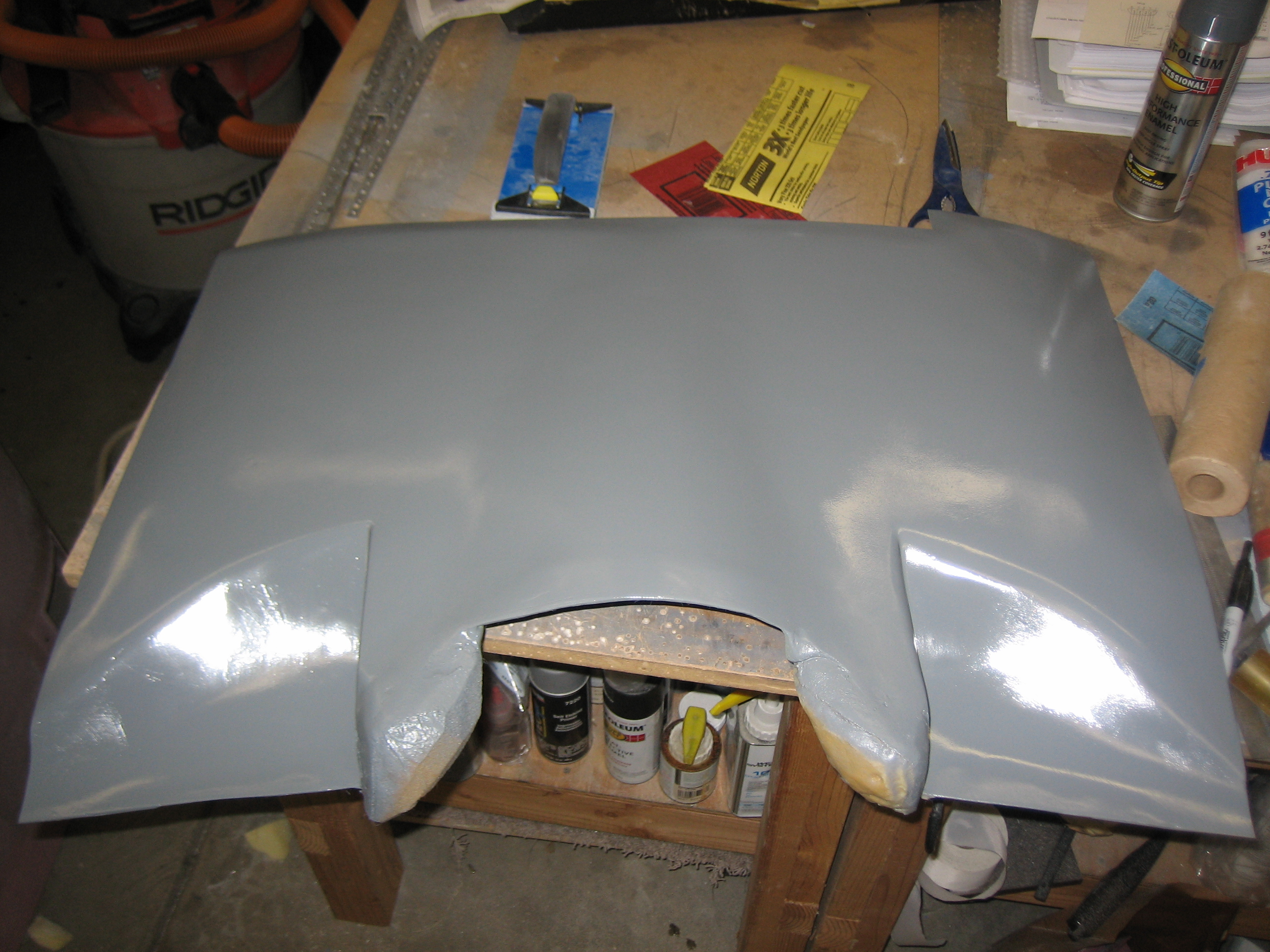
I sanded down the filler and then sprayed a few coats of enamel on the mold to provide a smooth surface to layup the plenum against.

I sanded down the filler and then sprayed a few coats of enamel on the mold to provide a smooth surface to layup the plenum against.
This picture looks almost exactly like the one from yesterday, but I have applied several coats of mold release wax and a couple of coats of mold release agent. The mold release agent is thinner than I expected and doesn’t really flow out like it ought to. I ended up using a brush to even out the surface a bit, but it still didn’t make a nice even coating.
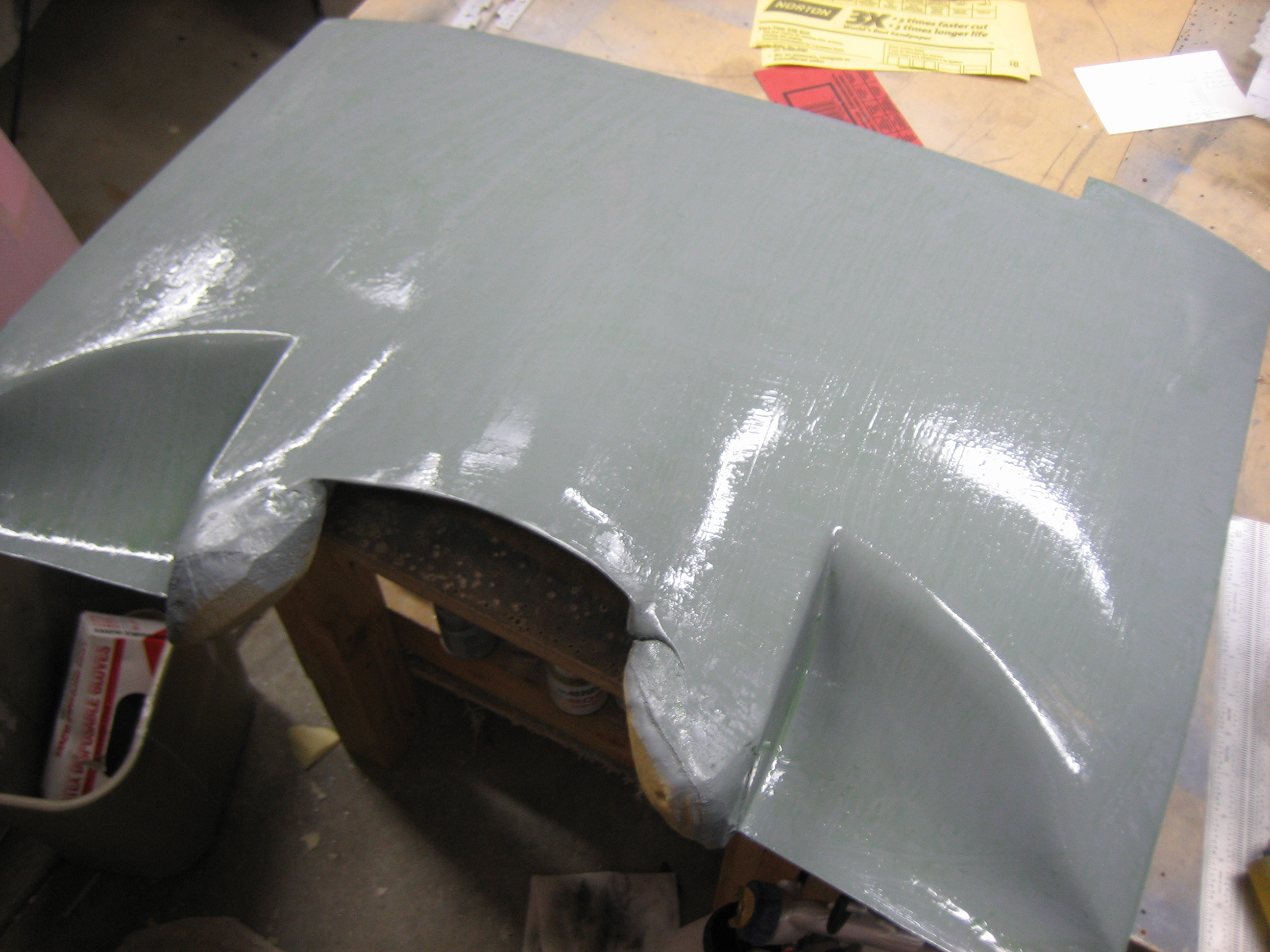
I started laying up the plenum tonight. I’m starting with two layers of glass because I’m going to have to narrow the inlets a bit and create little “ears” out the outer ends to attach the plenum to the baffles. I’ll layup a couple of additional layers once I’ve established the final shape.
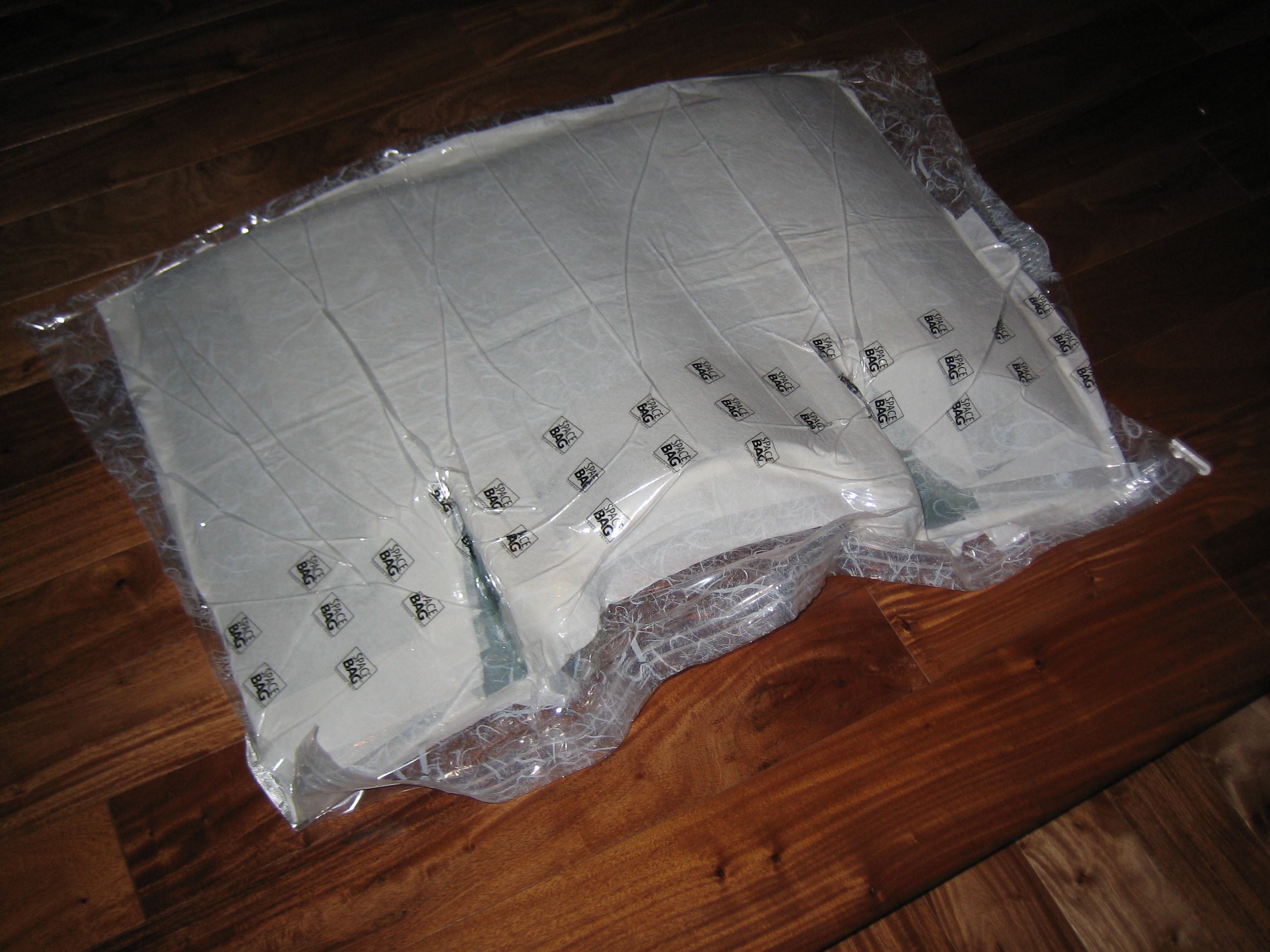
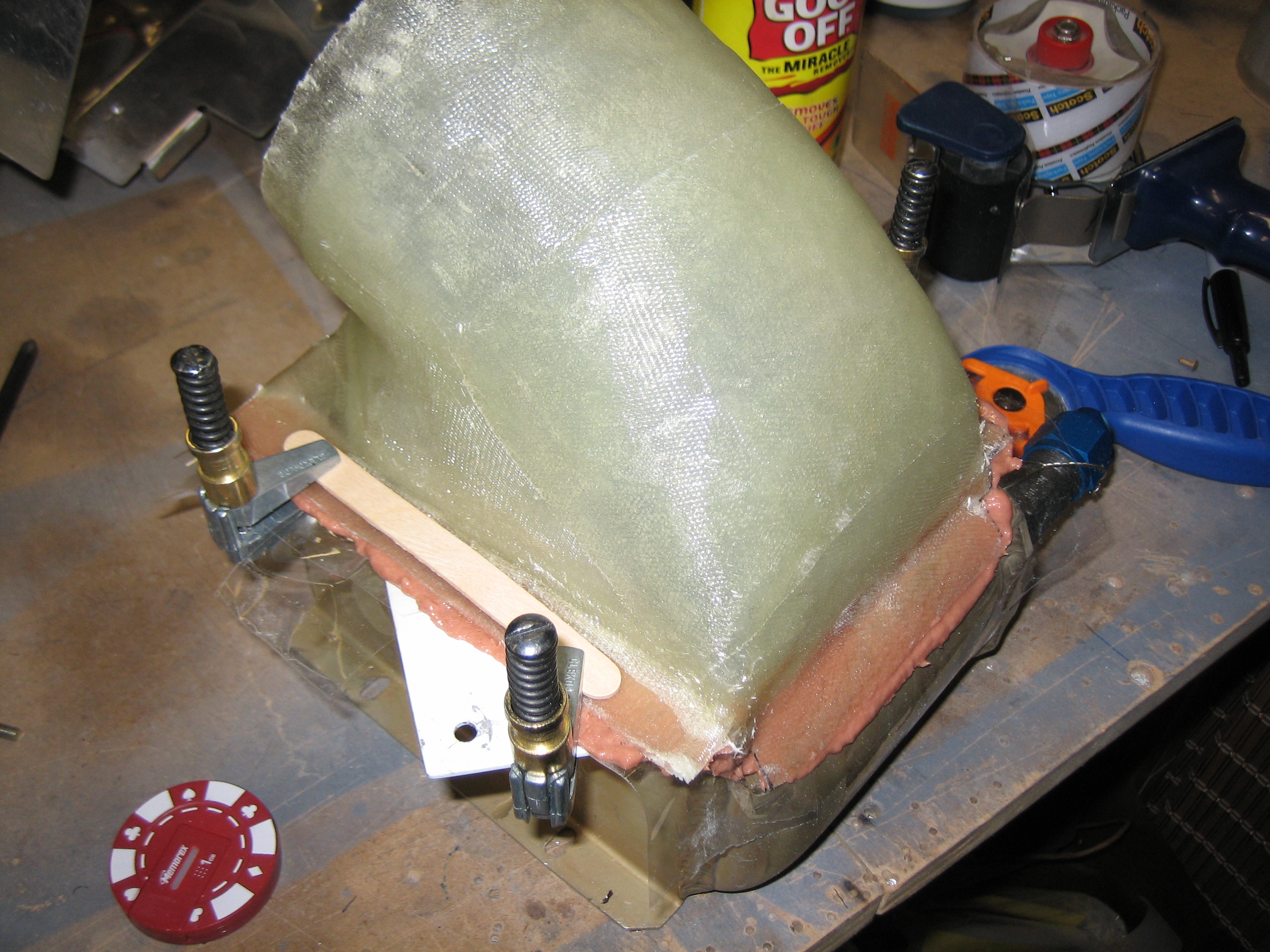
I had been considering buying the equipment to do vacuum bagging, but it’s fairly expensive and I don’t expect to do much of it. After thinking about it a bit though, I stumbled on a really cheap alternative. This is one of those Space Saver storage bags. Most of the bags they sell are too small, but they sell some larger bags labeled as hanging bags, the “suit” sized bag was perfect for the plenum and cost around $10. The material isn’t stretchy, so you’ll have to coerce it into corners, but there’s enough slack to do this. Over the two layers of glass, I added a full layer of Dacron and a couple of layers of paper towels to absorb excess resin. I then used our vacuum cleaner to suck out all of the air. This worked surprisingly well, and the vacuum was still maintained the next morning.
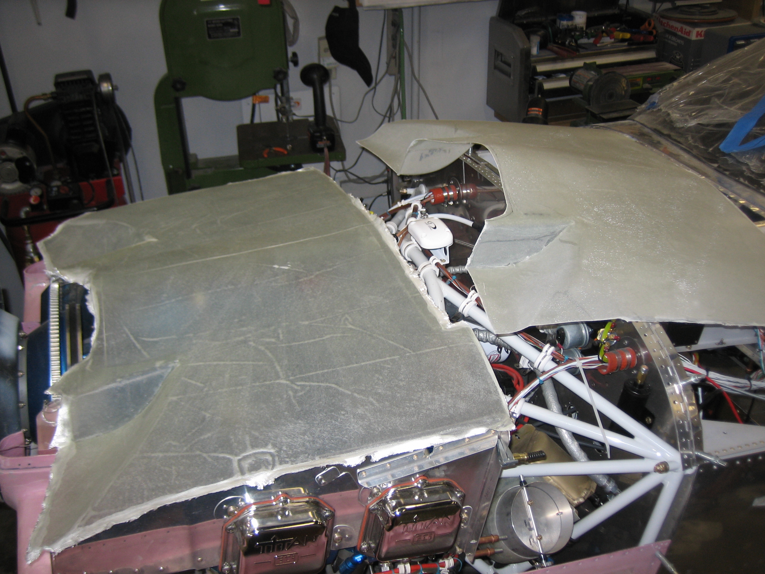
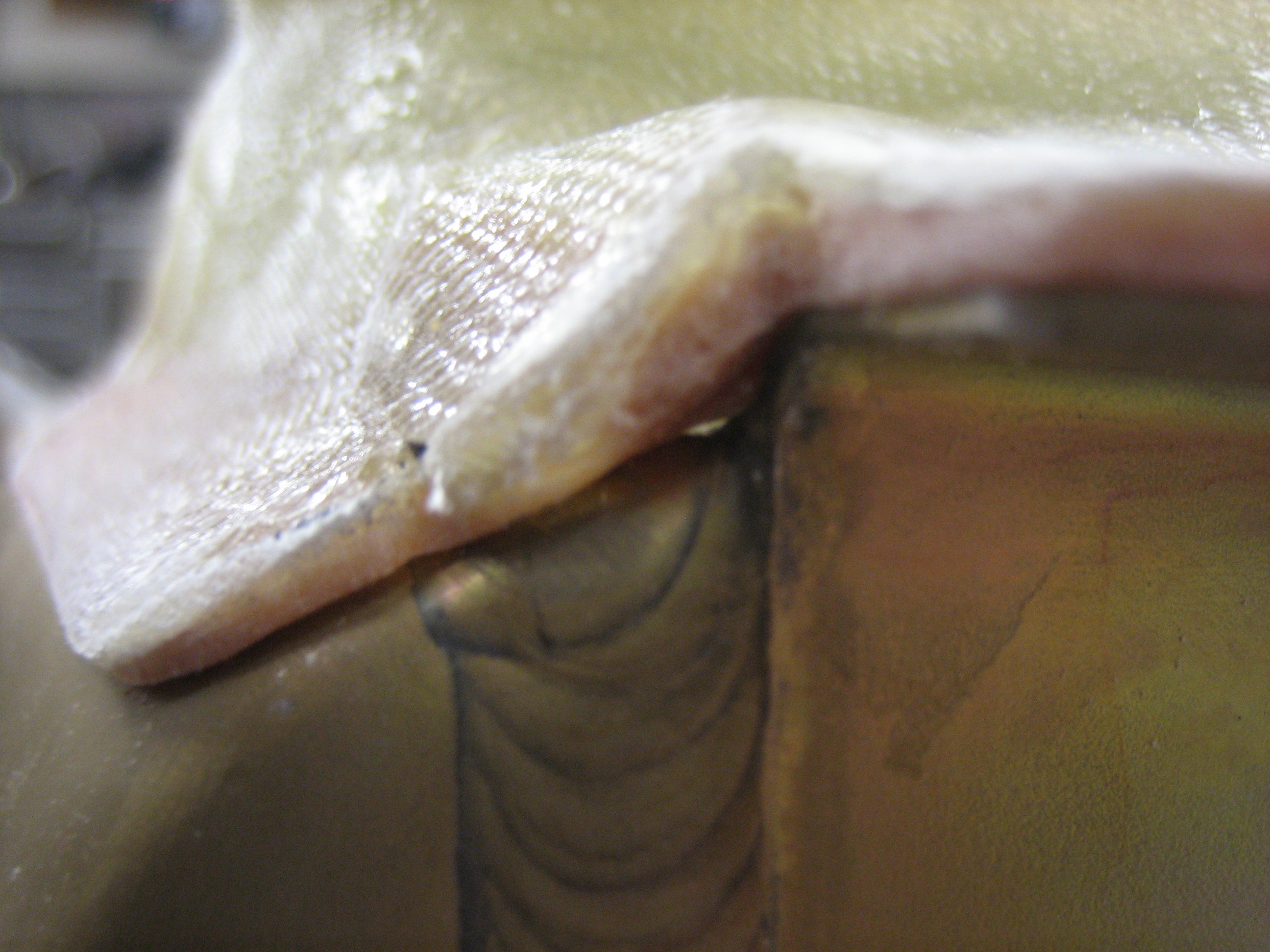
I popped the plenum out of the mold and roughly trimmed it to the baffles. The fit is pretty good, but there will definitely have to be some tweaks.
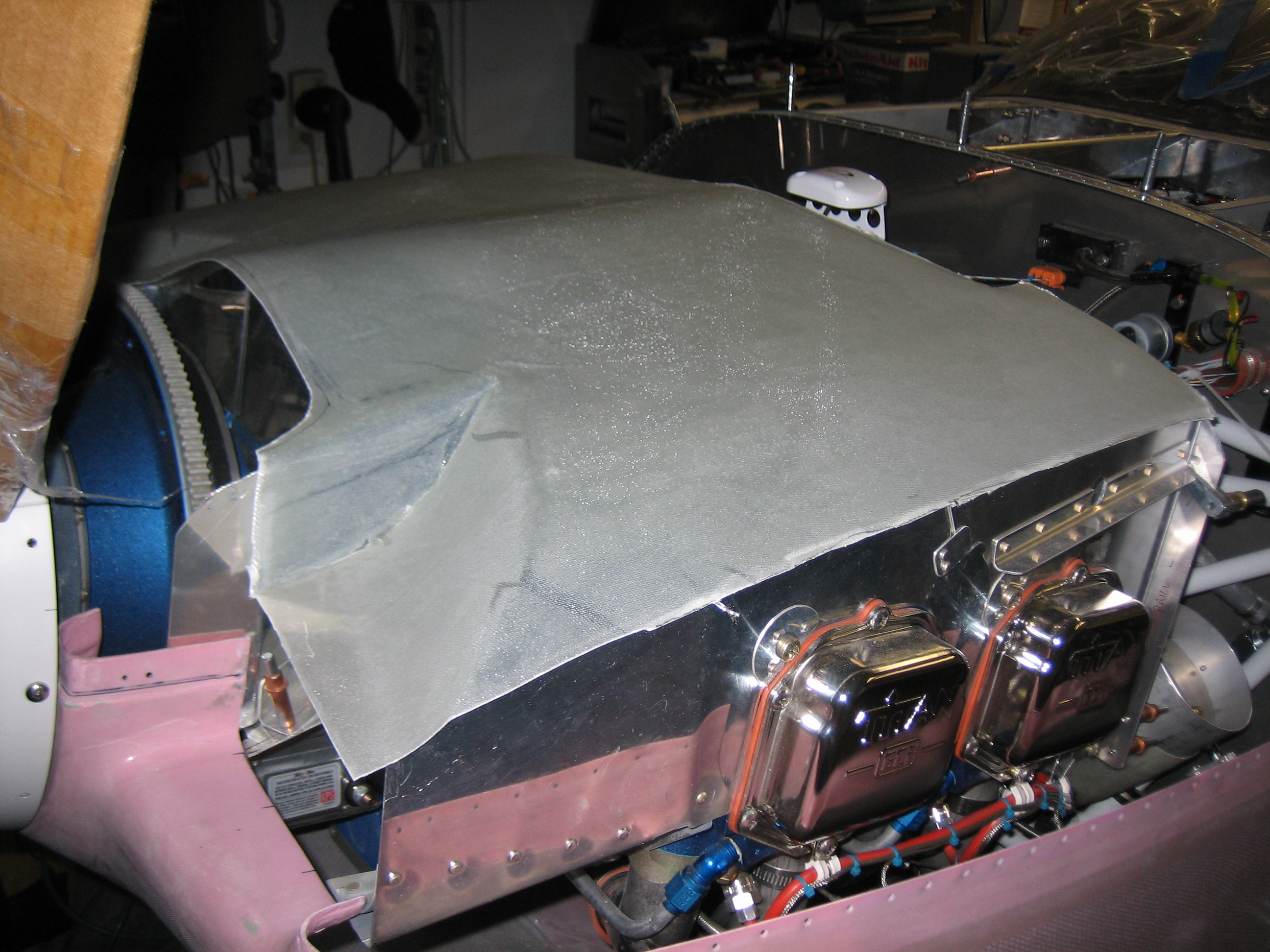
These corners were touching the underside of the top cowl. I’ll want a good 3/8″ of clearance between the top of the plenum and the button of the top cowl to allow for engine movement. I trimmed the forward aluminum baffles in order to lower this part of the plenum almost 1/2″. Unfortunately, this lowers the inboard edge of the ramps a little too much. I’ll have to cut and reglass the side of the ramp to raise the forward edge slightly. I’m really glad I only laid up two layers of glass so far as it makes it really easy to bend and cut. I’ll probably end up laying up the additional layers right on the engine so that the plenum fit perfectly.
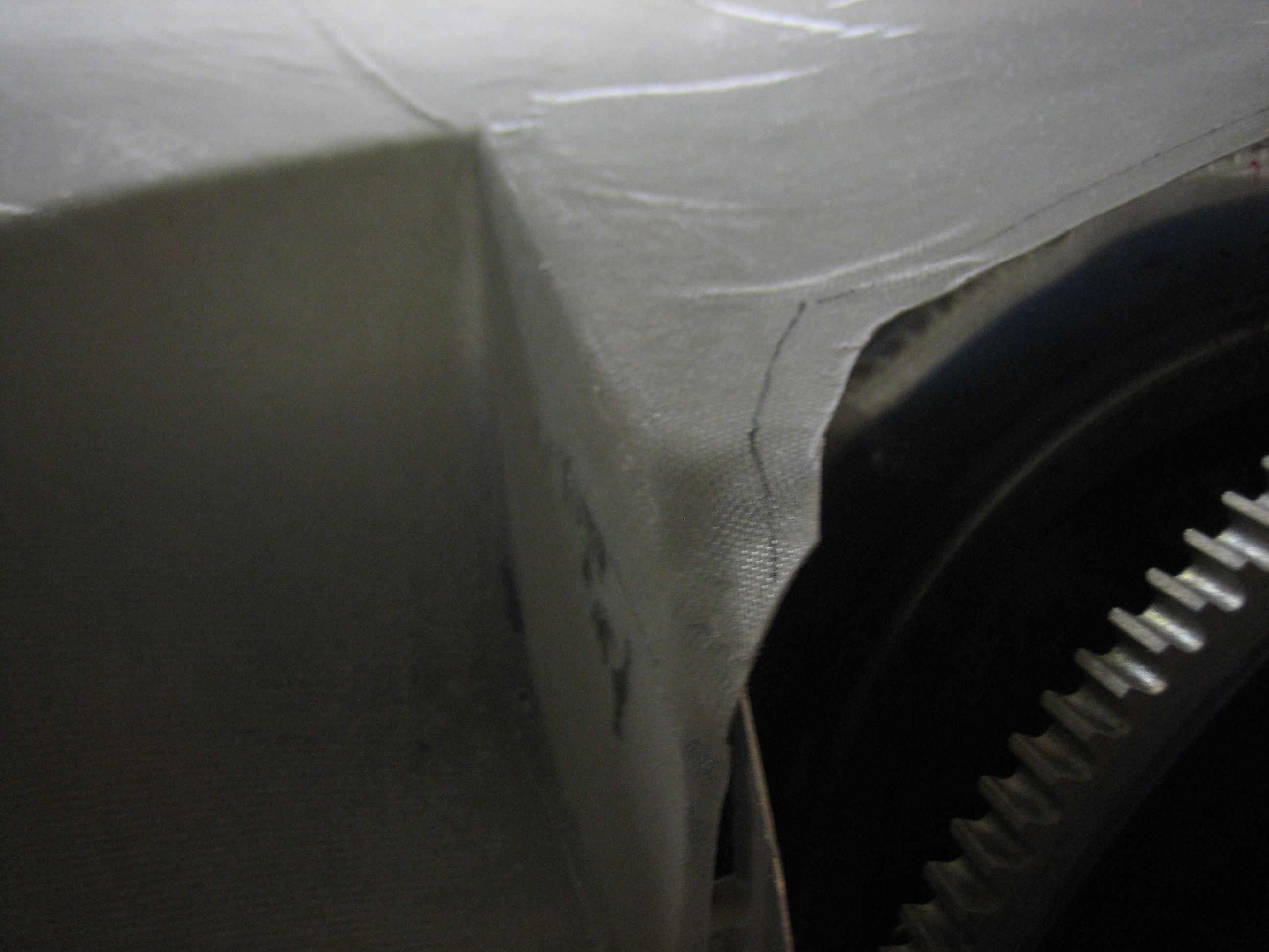
The outboard edges need to come down quite a bit. The inlets are quite a bit shorter at their outer ends than their inner ends. I’ll have to trim the side baffles to allow this to come down.
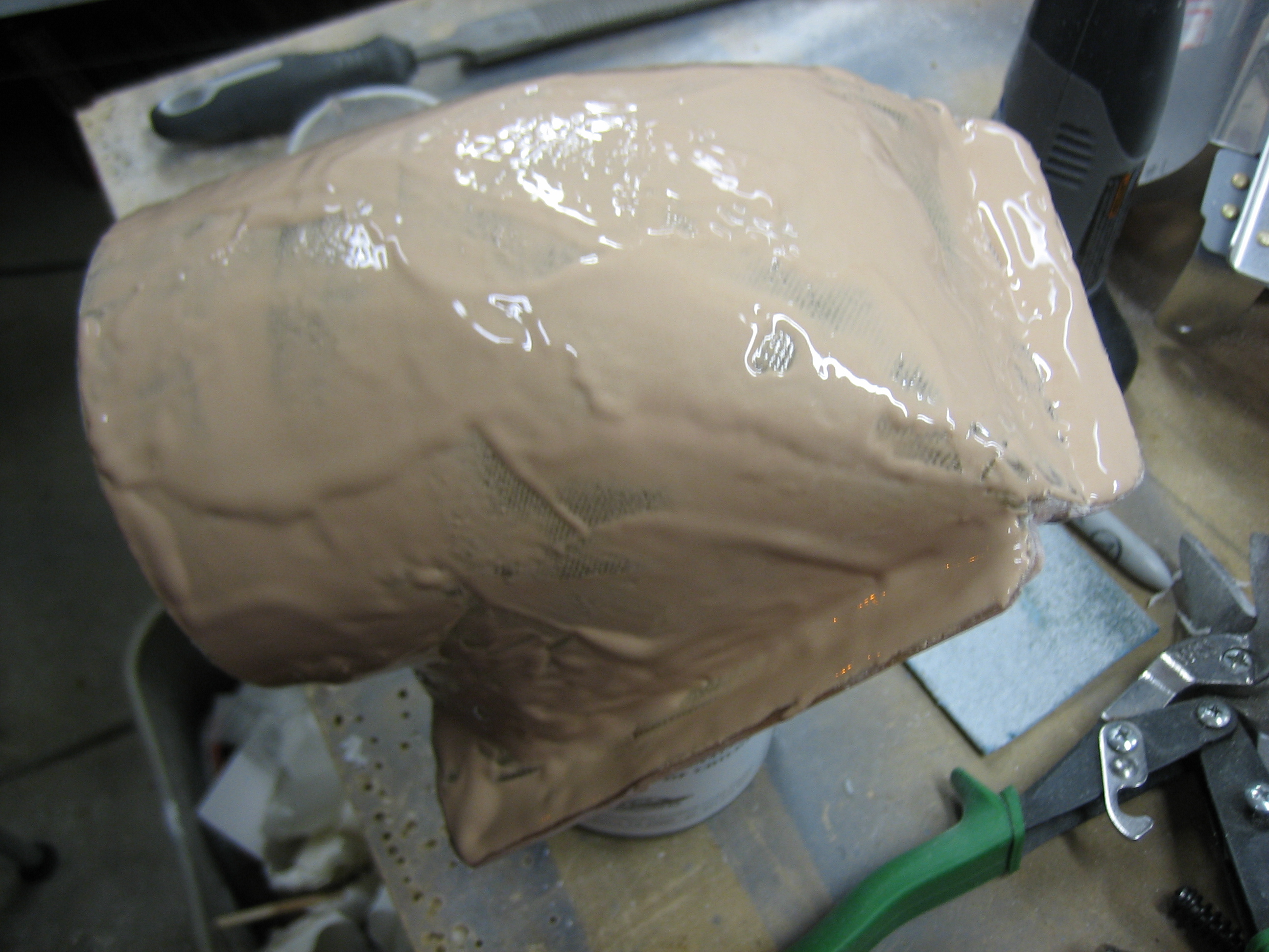
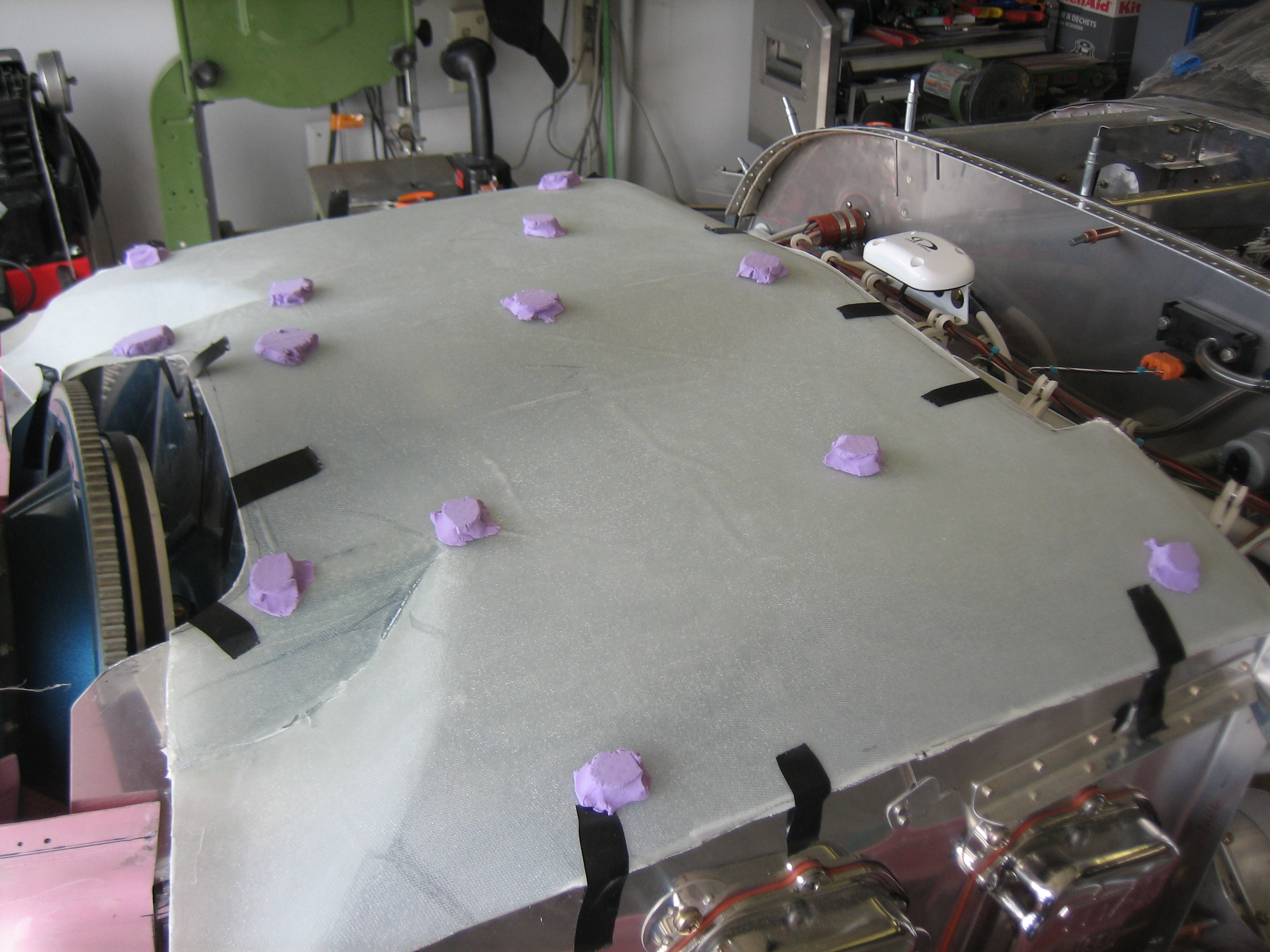
I wanted to ensure that there is sufficient clearance between the cowl and the plenum across the entire plenum. I came up with the idea of placing blobs of something on top of the plenum and then installing the top cowl. I wanted something that would deform pretty easily so that it wouldn’t deflect the plenum, but stiff enough that it will stand up by itself without sagging. My wife suggested a product called Moon Dough that my son had. This worked perfectly. It deforms with practically zero pressure, but won’t move on it’s on. As you can see, the blobs flattened down nicely and perfectly reveal the clearance at each point. I measured all of these, and they’re all very close to 1/2″. I’m going to trim the baffles down another 1/8″, but the thickness of the plenum and the screw heads will eat up some of the clearance. I should end up with at least 3/8″ all the way around.
For some reason, I didn’t remember until days after fabricating the first plenum that I didn’t use the high-temp epoxy that I bought. I thought about just using it for the additional layers of the first plenum, but decided it wouldn’t be that much more work to just lay up an additional plenum. This epoxy is definitely more brittle than West System epoxy. I’m hoping it toughens up after adding a few more layers and post-curing it at high temperatures.
After trimming all of the baffles down an additional 1/8″, I laid out, drilled and riveted the #4 side baffle to the aft wall. I dimpled the other flanges (the one with the clecos) so that the inside face will have flush rivets. I’ll back rivet these, but it’s too late to run the rivet gun tonight.
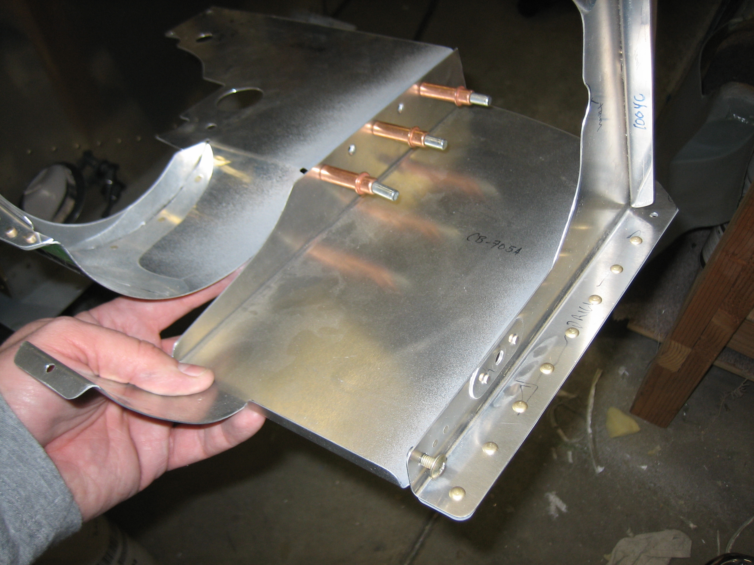
I also riveted the #3 side baffle to the aft wall on the right side. I also trimmed the bottom outside corner to clear the manifold pressure fitting.
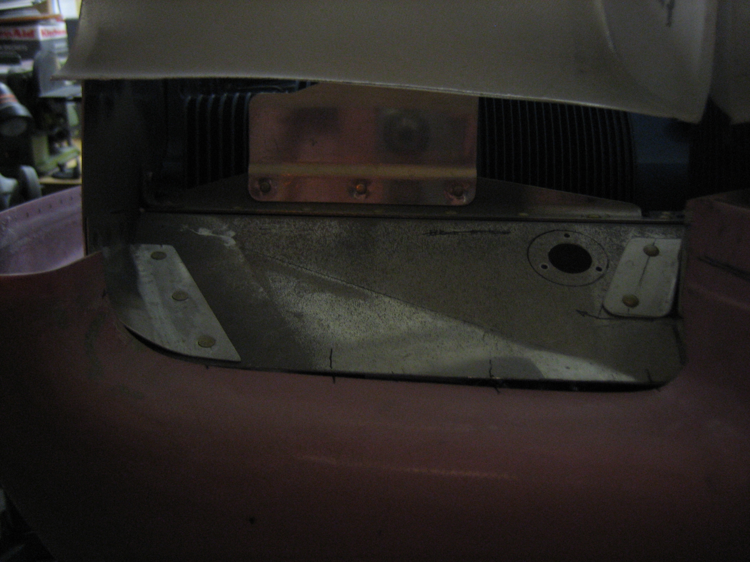
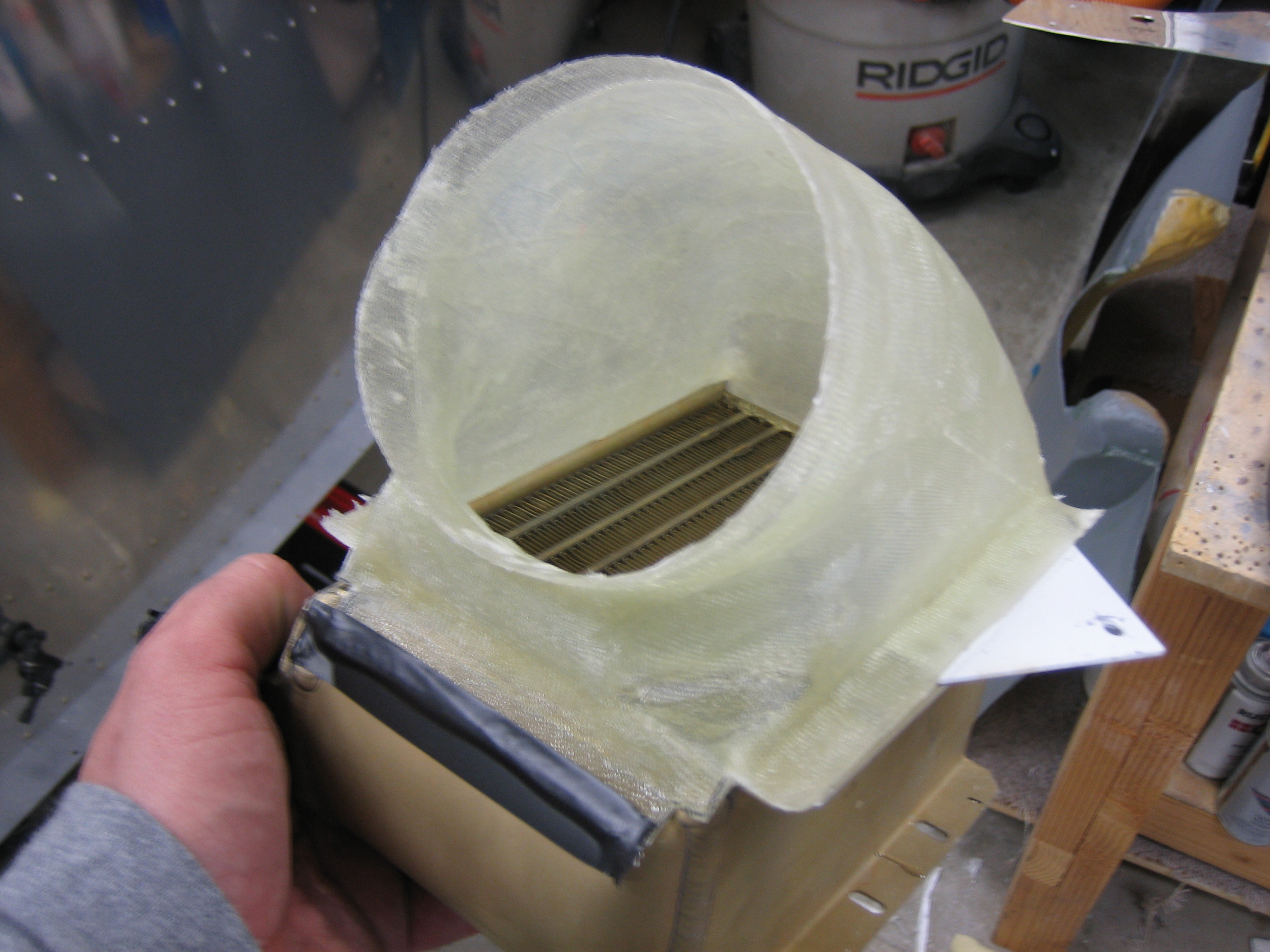
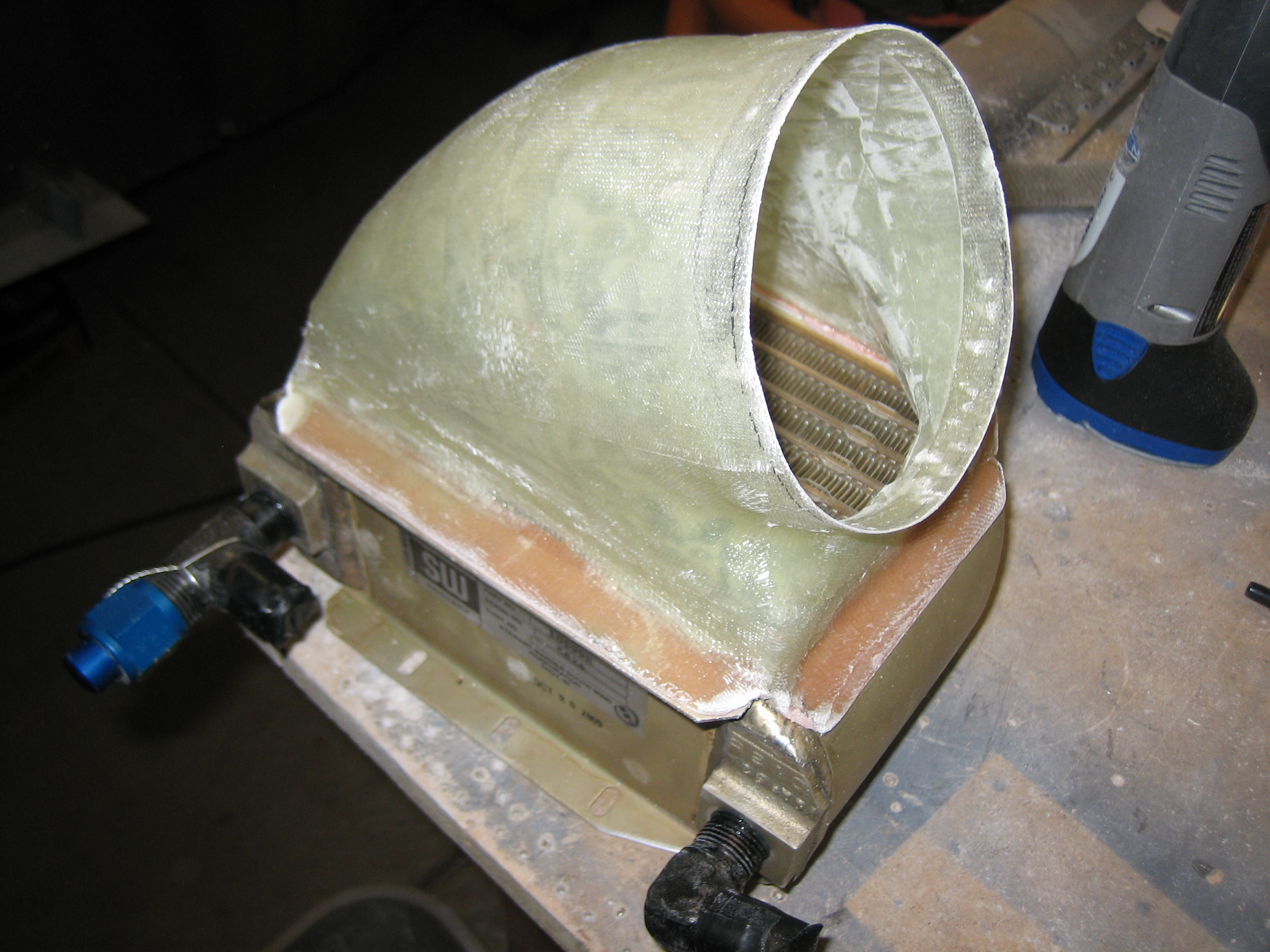
Last night, I laid up some additional glass over the oil cooler plenum using the high-temperature epoxy. You can see here that I wrapped the epoxy down the side of the oil cooler. I also extended the circular flange forward another 1/2″ or so to make it easier to mount the butterfly valve.
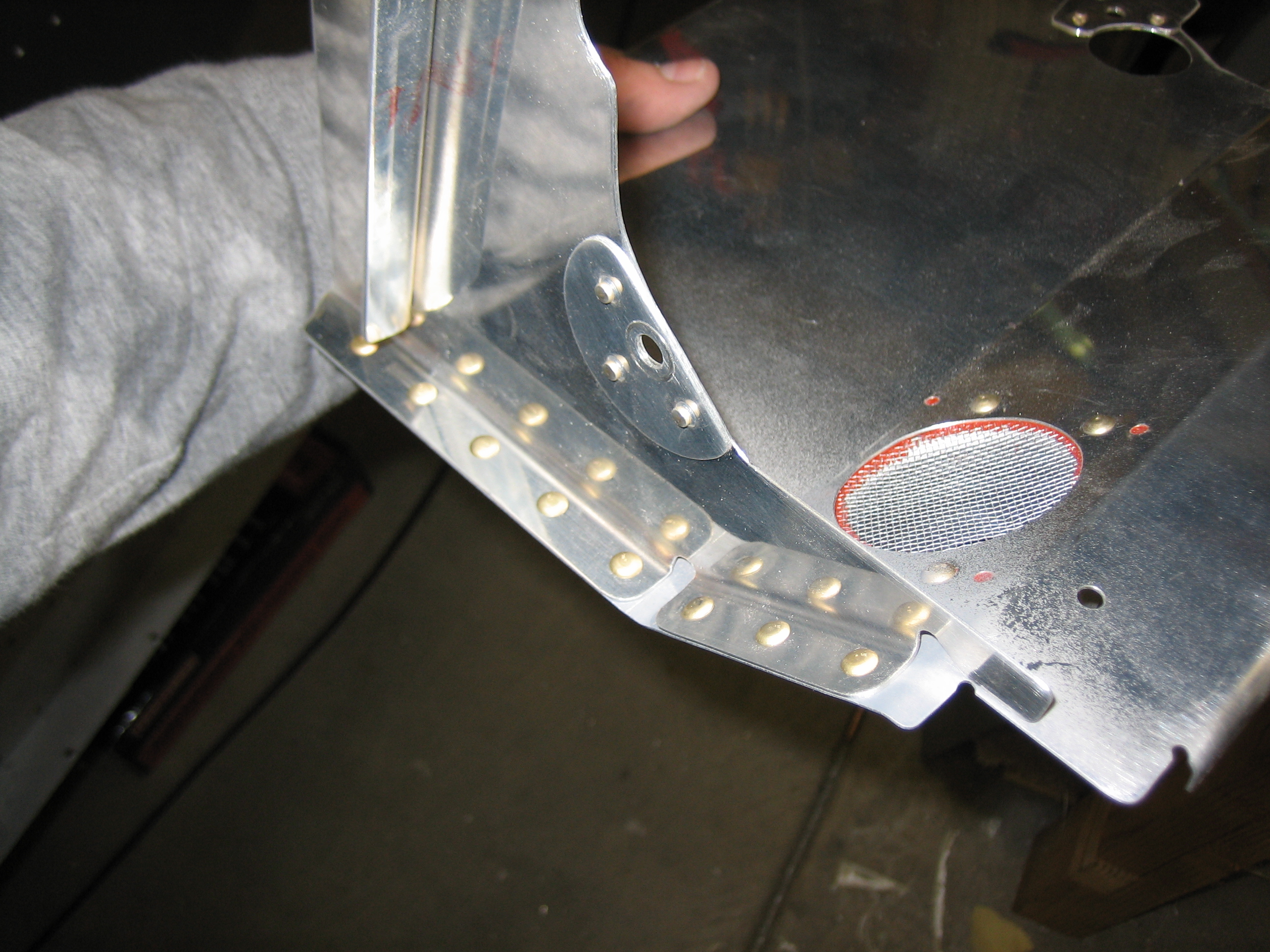
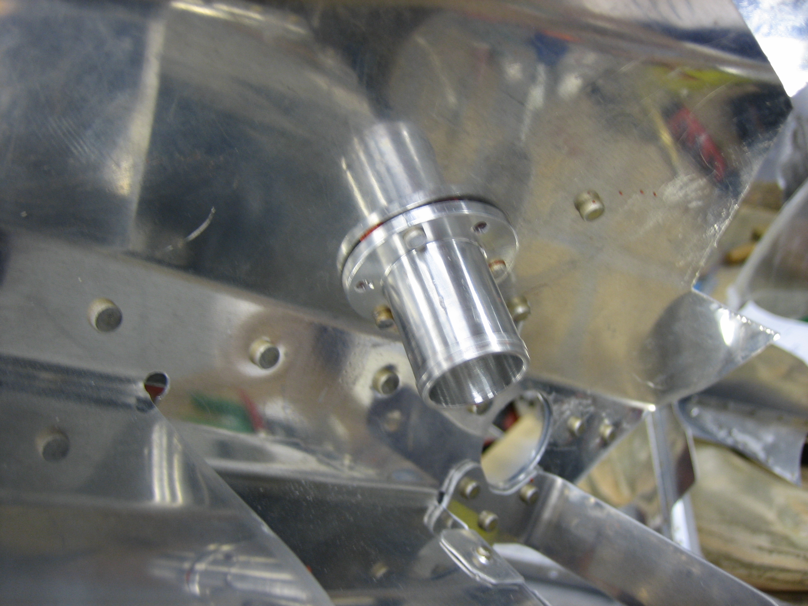
I riveted the blast tube flanges on to the baffles along with some stainless steel mesh to keep out the bugs and debris. This is the one on the front right baffles that sends cooling air to the alternator.
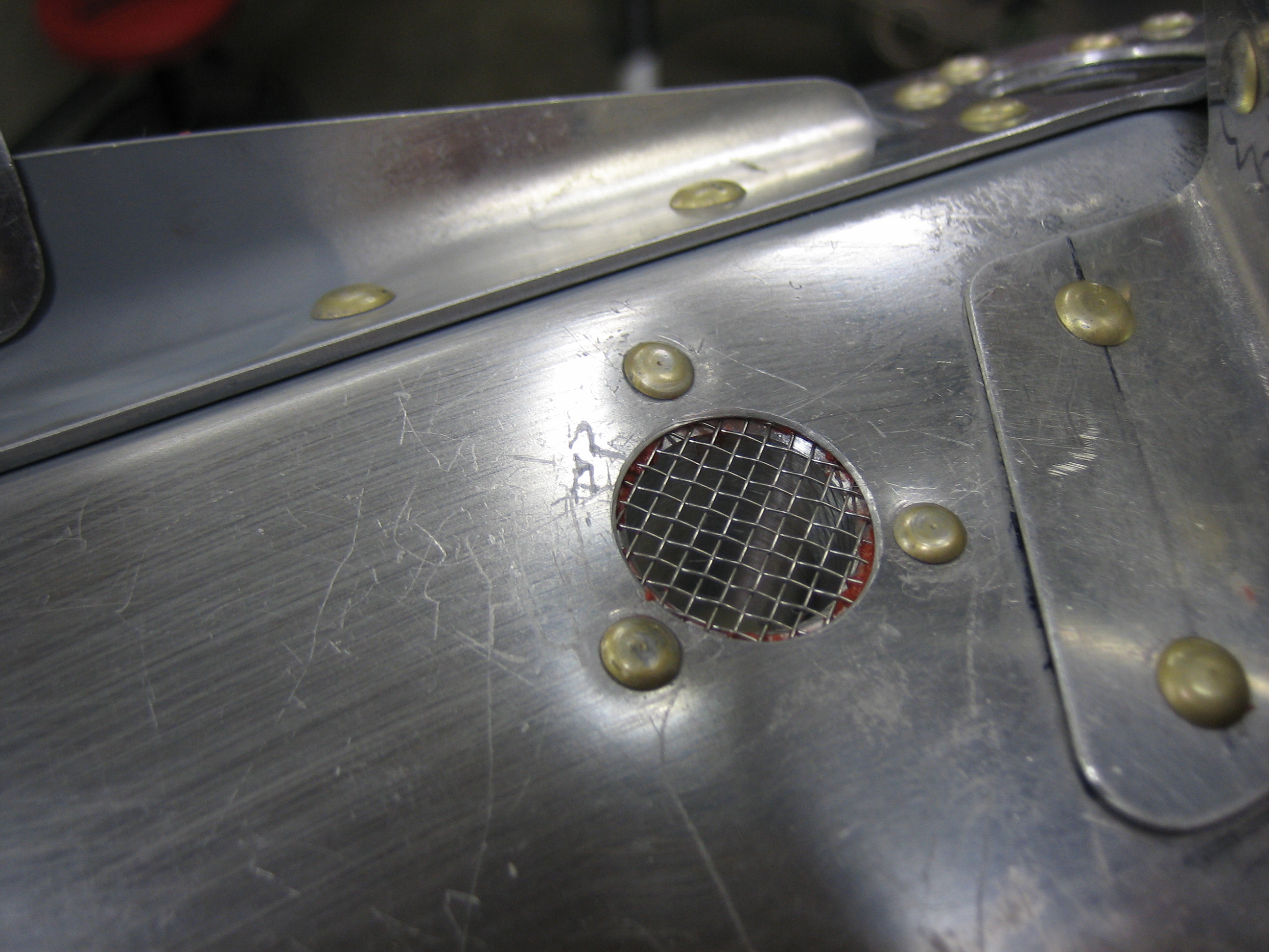
Here is the underside of this flange. There is high-temp RTV between the flange and baffles to seal any air leaks.
I also riveted one of the left rear baffle to send cooling air to the magneto.
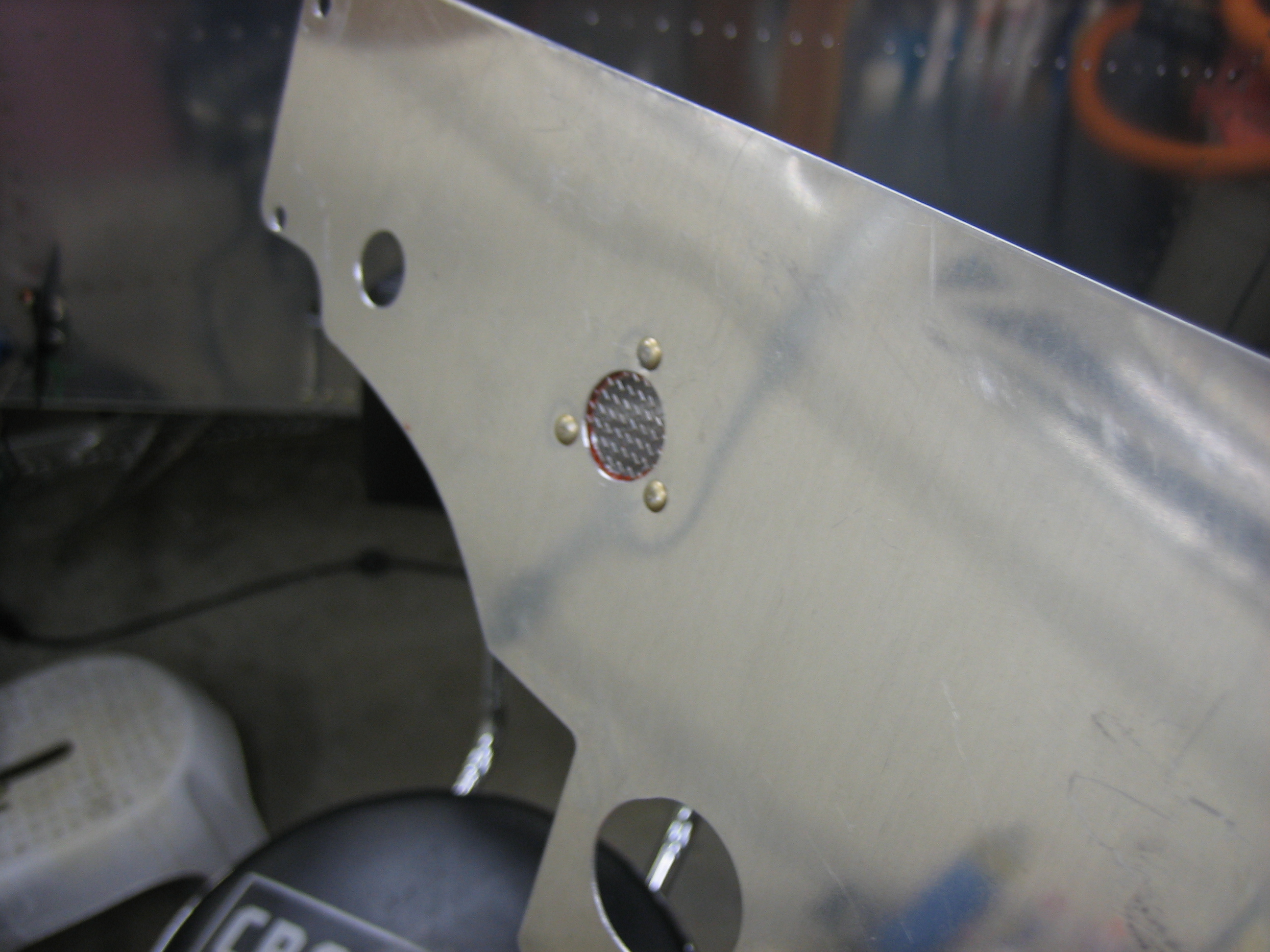
Here’s the back side of this flange.
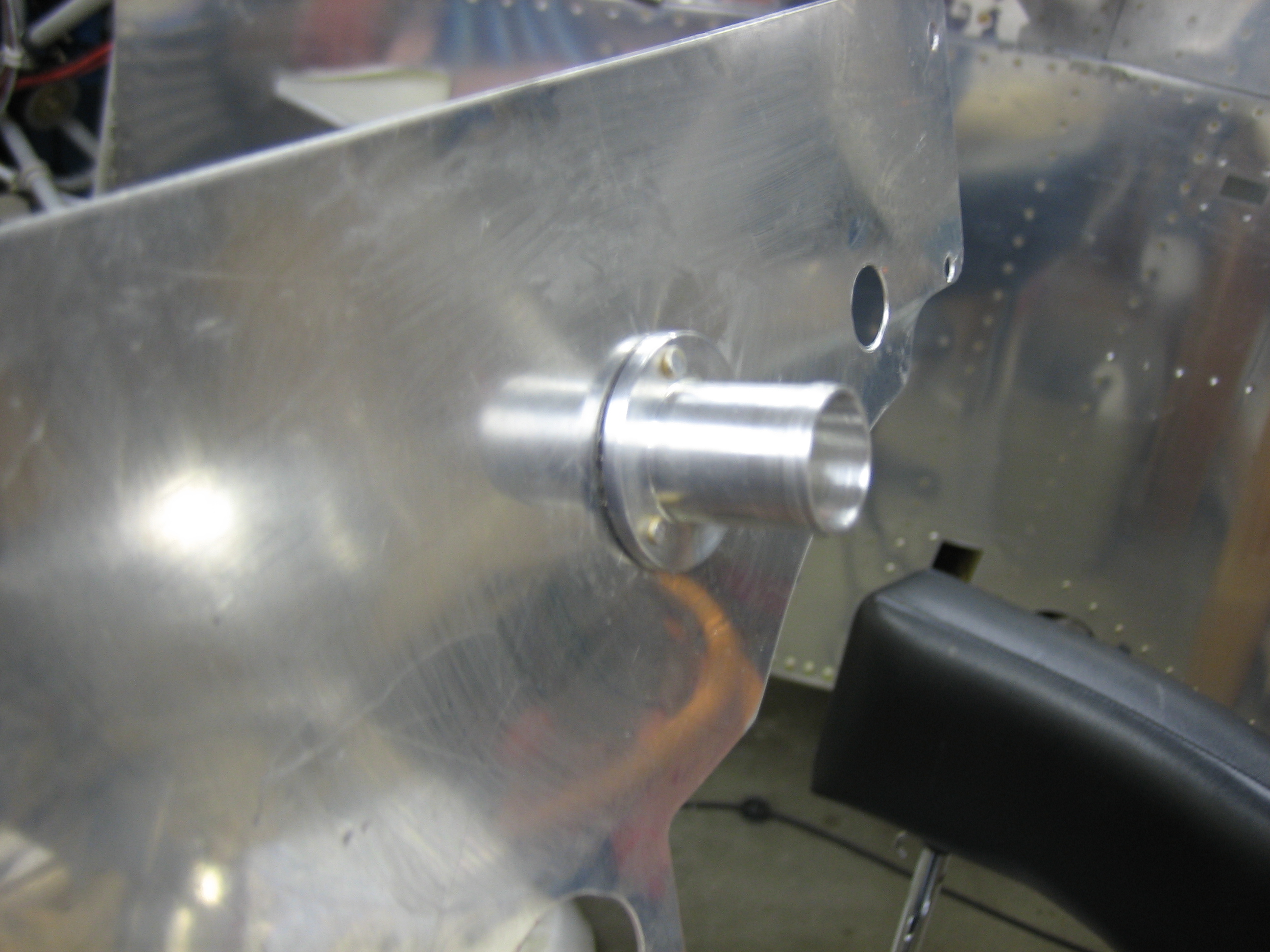
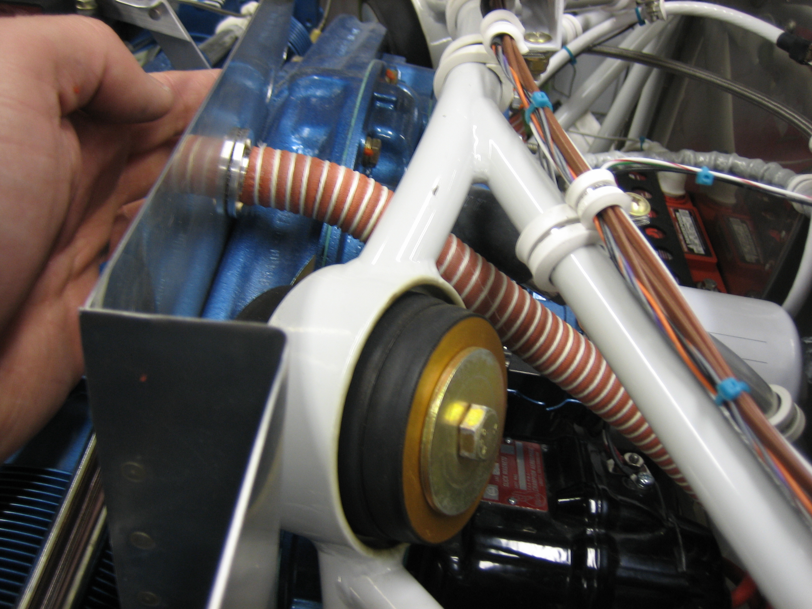
Here’s where this fits in relation to the magneto. This duct is obviously too long, but it shows the routing to the magneto. I’ll anchor the other end with an adel clamp anchored to the upper oil line.
I mixed up some epoxy/flox and applied it to the mounting faces of the oil cooler plenum to fill in any imperfections and stiffen the flanges. The oil cooler is covered with packing tape to prevent the epoxy from sticking.
I trimmed the excess epoxy/flox mixture from the edges of the flanges and made the intake square to the opening and flat.
The flox mixture allowed the flanges to fit perfectly over the flange extension.
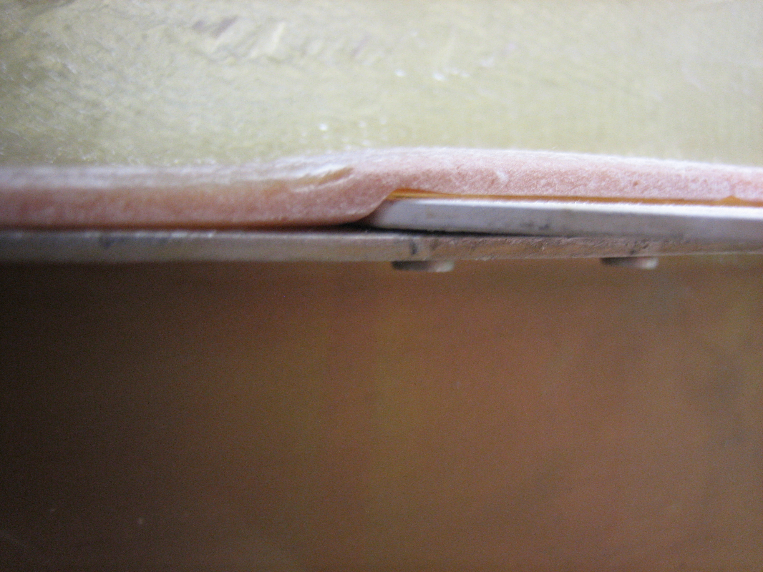
And filled in nicely where the flanges end. There will be some high-temp RTV between the mounting surfaces to seal any small openings.
I mixed up some epoxy with lightweight filler and buttered up the surface to smooth it out. This should be cured enough to sand by tomorrow.