Test Install of Gear Leg Fairings

After grinding down some of the excess flox inside the gear leg fairings, I cut some slots for the hose clamp and installed the gear leg fairings on the airplane.  I’ll do a proper alignment with the longitudinal axis of the airplane later, but for now I used the upper intersection fairings to align these.

Here’s what the upper end of the fairing looks like.  You can see that I also drilled a hole forward of the slots to access the worm clamp’s adjustment screw.  All of this is hidden inside the upper intersection fairing once that is installed.

Aligned Gear Leg Fairings and Wheel Pants

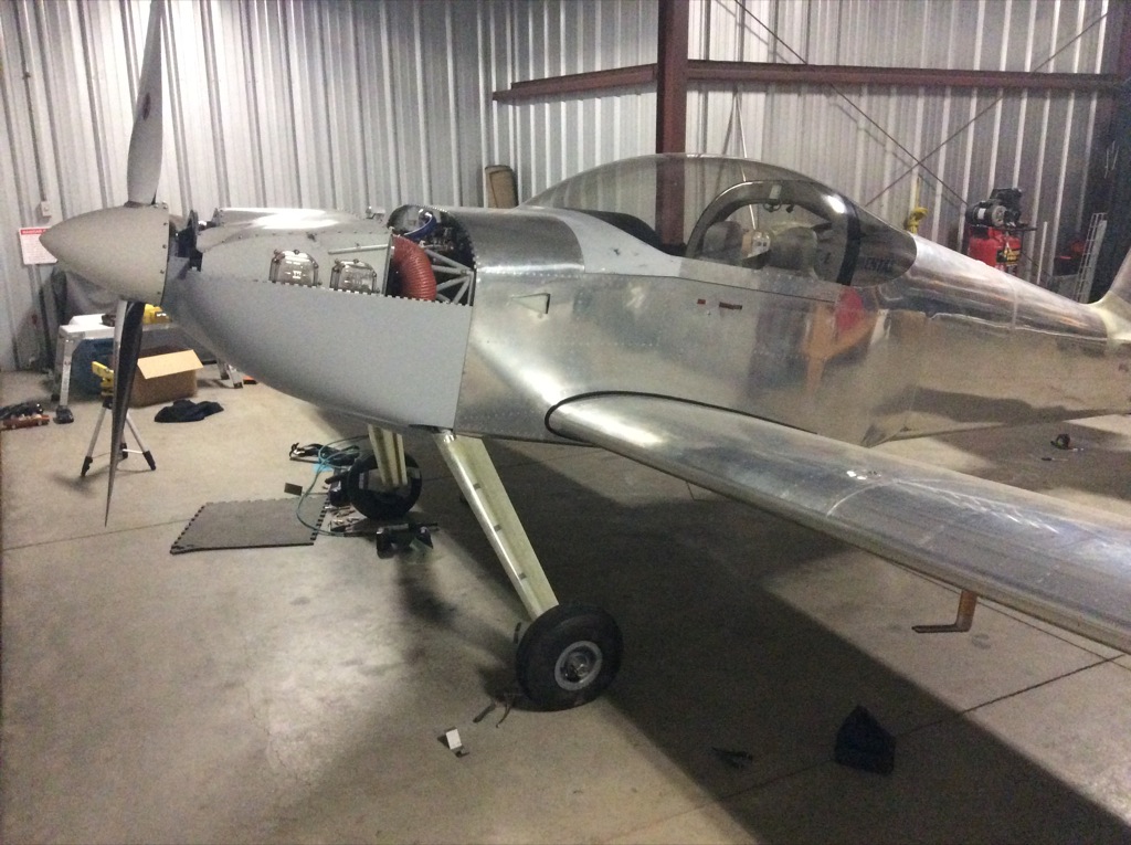
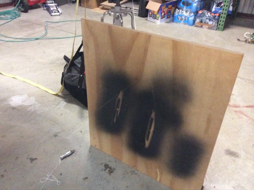
I put the plane up on jacks and dropped a couple of plumb bobs along the center line.  I then snapped a chalk line on the floor so I can use it as a reference for aligning the gear leg fairings and wheel pants.

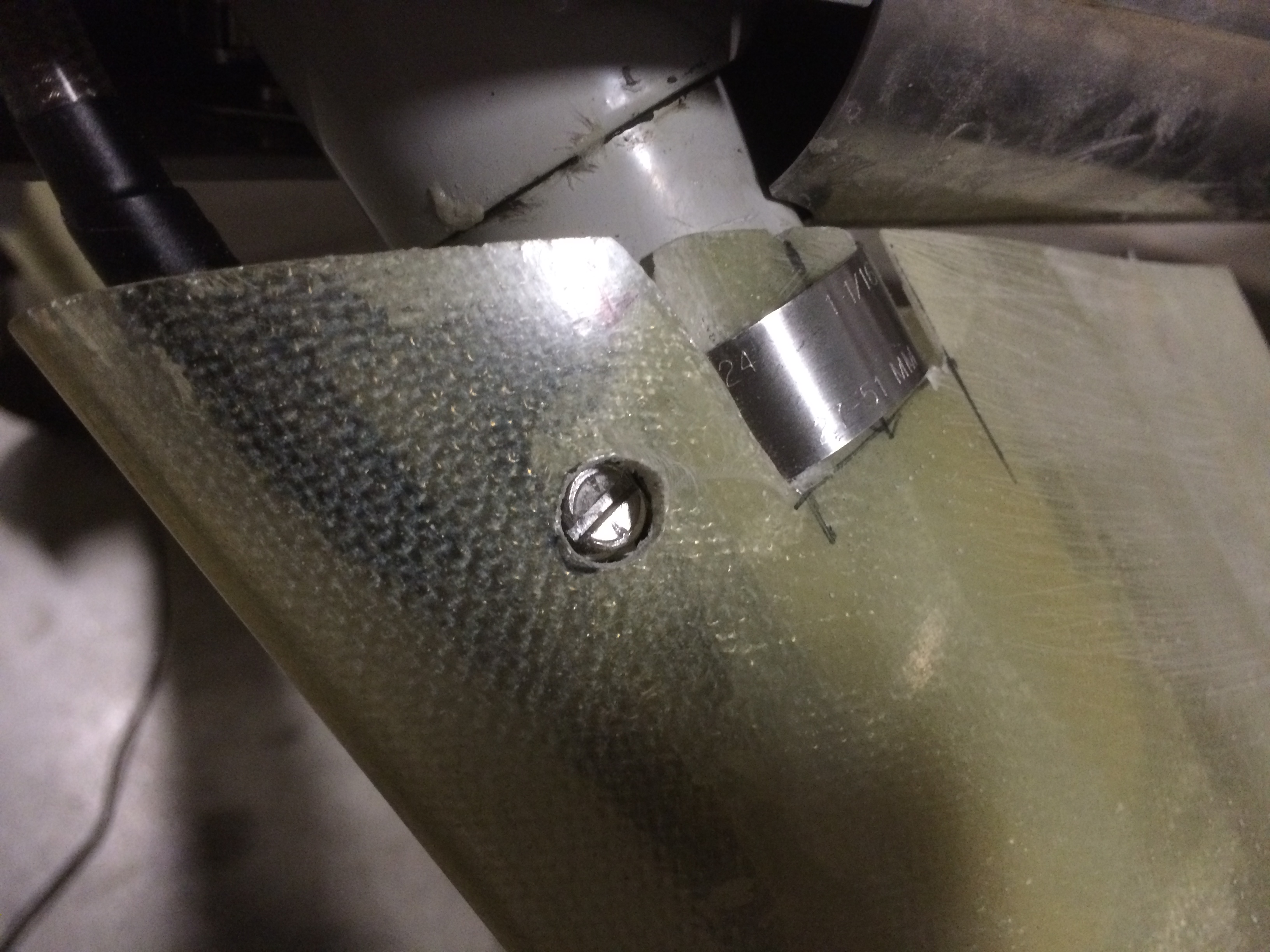
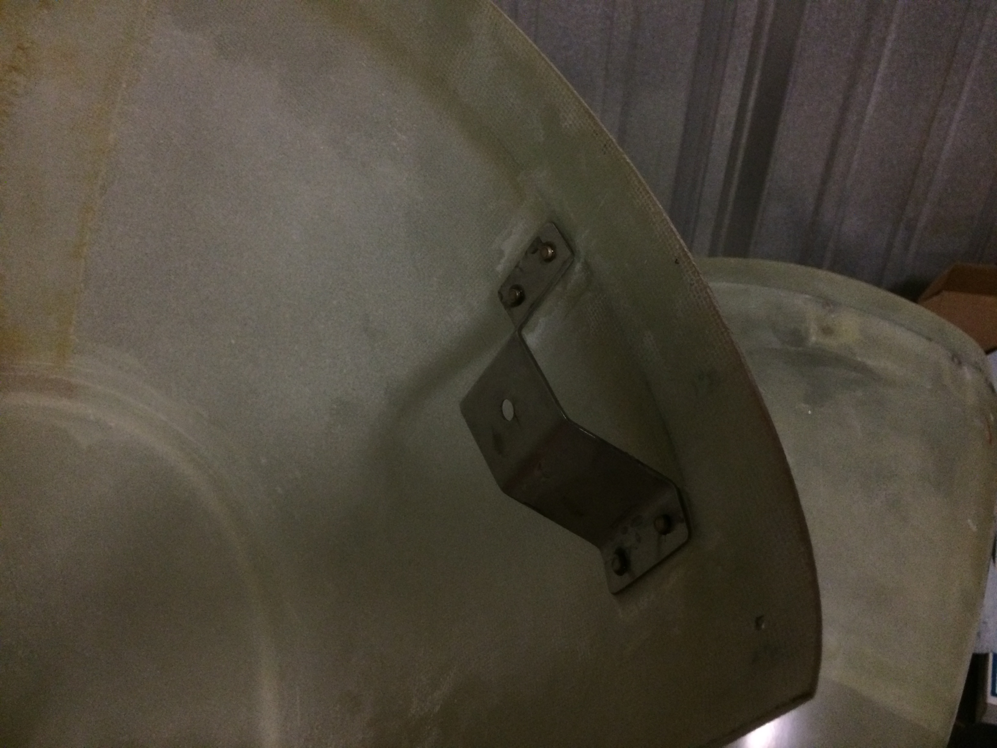
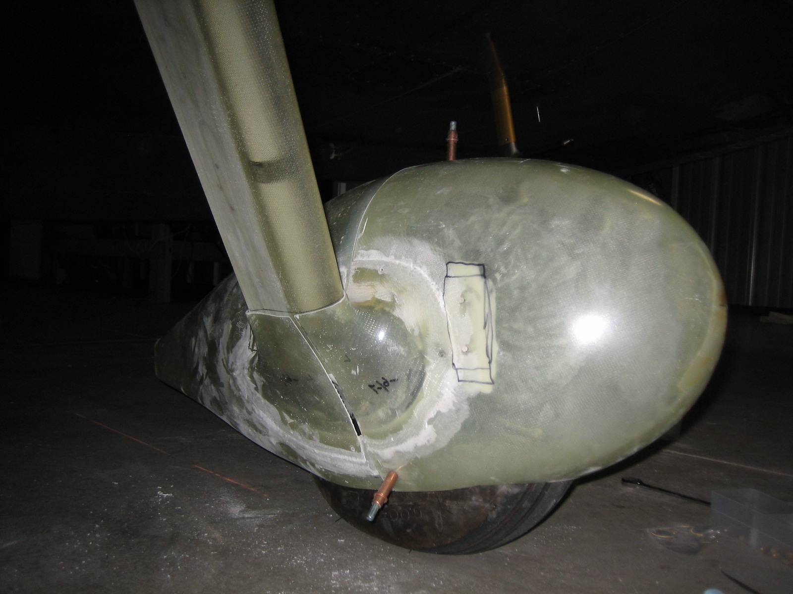
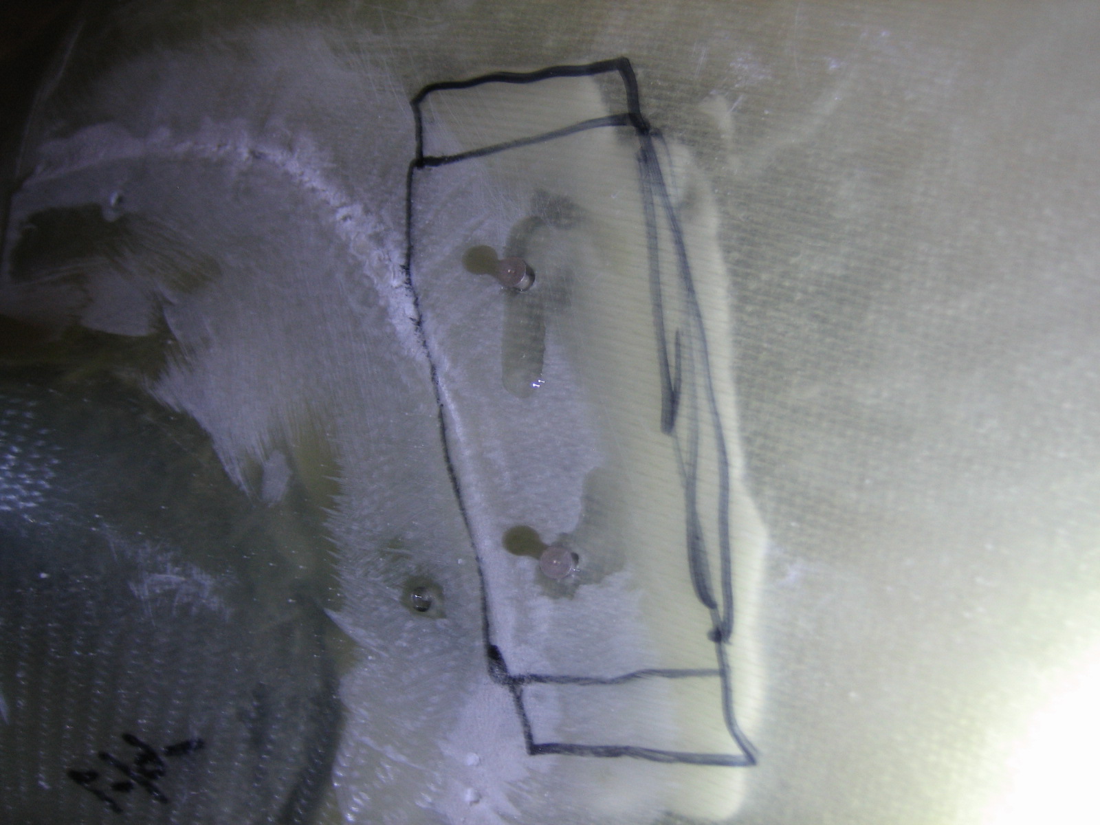
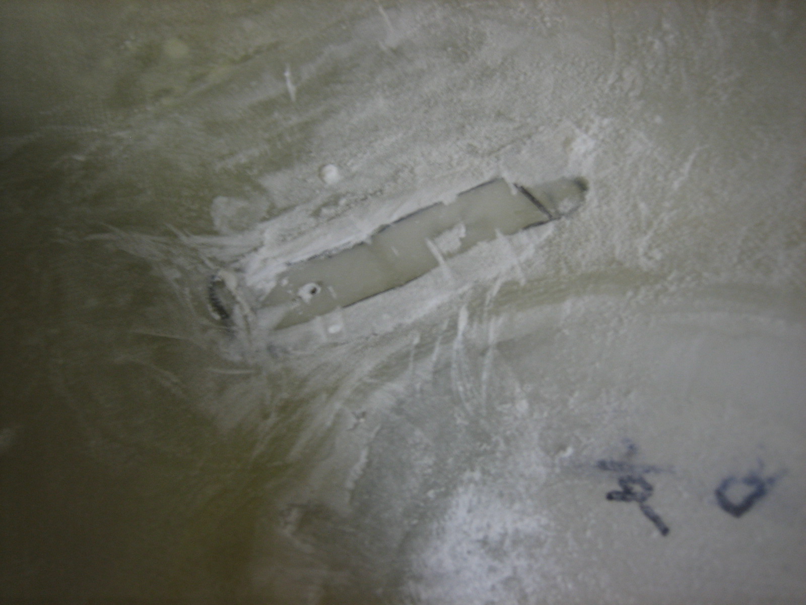
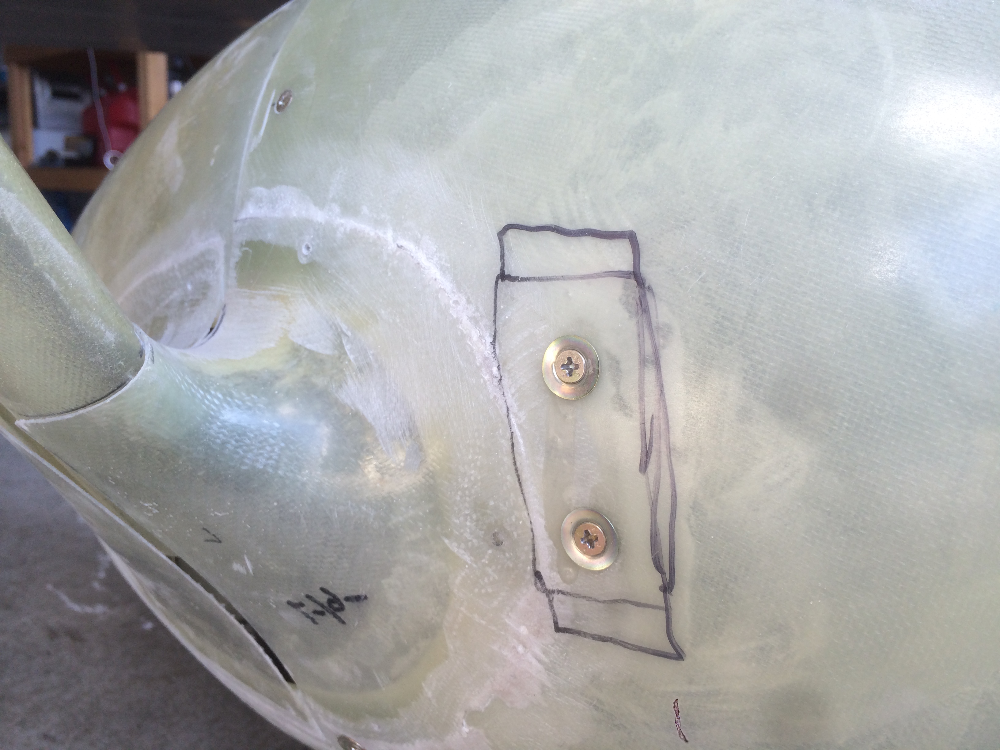
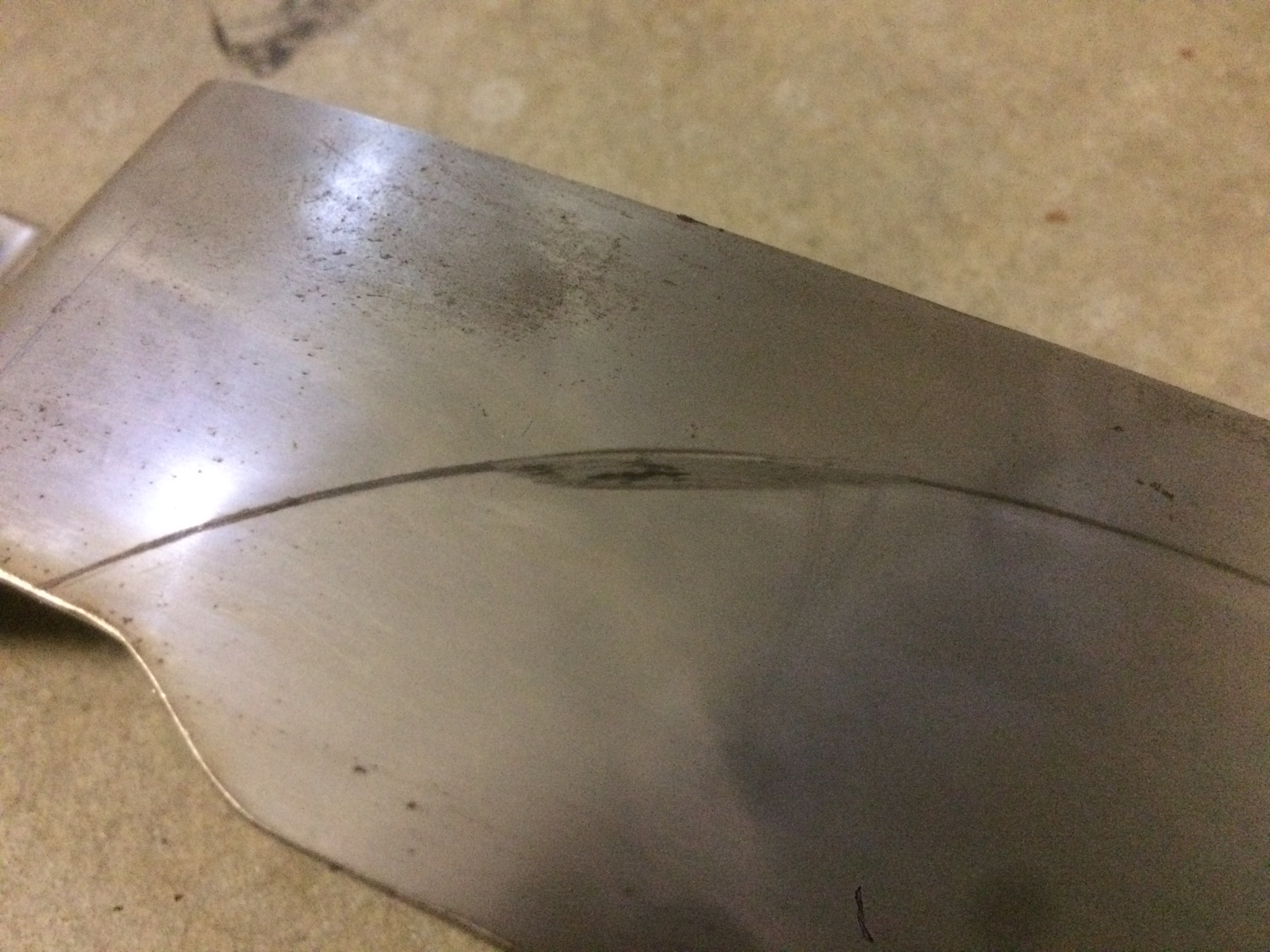
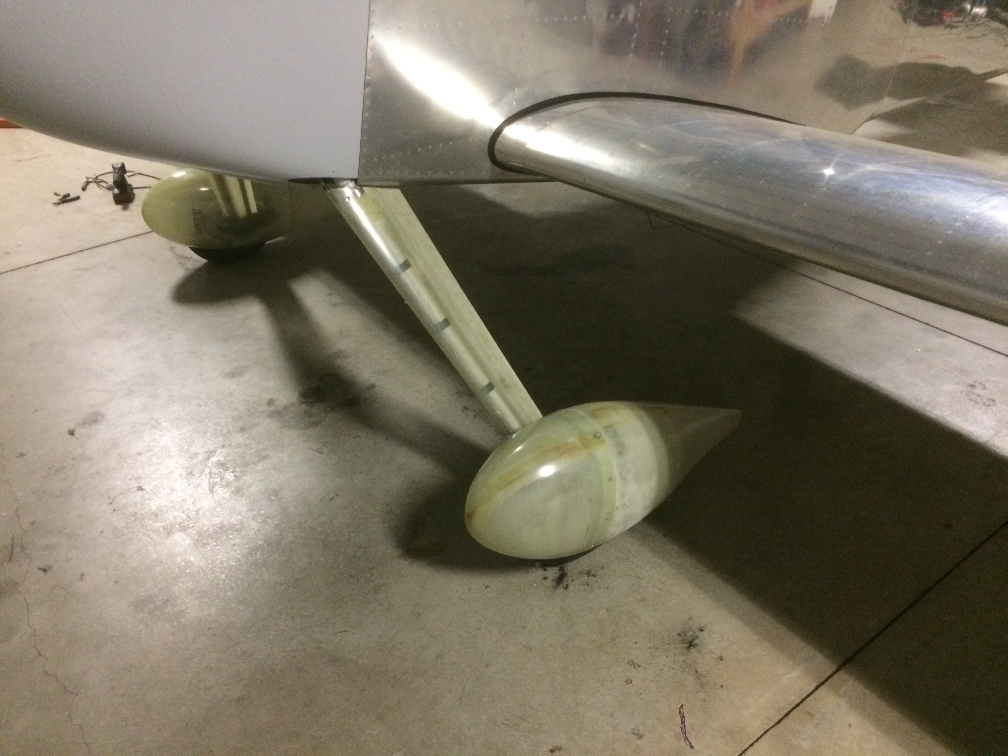
I created a second chalk line parallel to the aircraft centerline, but 38 5/8″ away which was roughly under the centerline of the wheel pant.  I then used a piece of scrap aluminum with a  square corner to measure up from the ground 8 5/8″ front and back to get the wheel pant parallel to the centerline of the airplane.  I blocked up the aft end with my chock to hold it there.  After aligning the wheel pant left to right (as shown in the next picture), I used one of my laser levels to mark where to drill (I aligned it with the hole with the front half of the wheel pant off and then reinstalled it).

The aft edge of the wheel pant needed to be pulled out a little bit to align with the centerline, so I used a ratcheting strap to the aircraft jack to pull it out until it aligned with the chalk line I snapped.  After everything was aligned, I drilled the holes through the inner fairing mount to lock in the position.

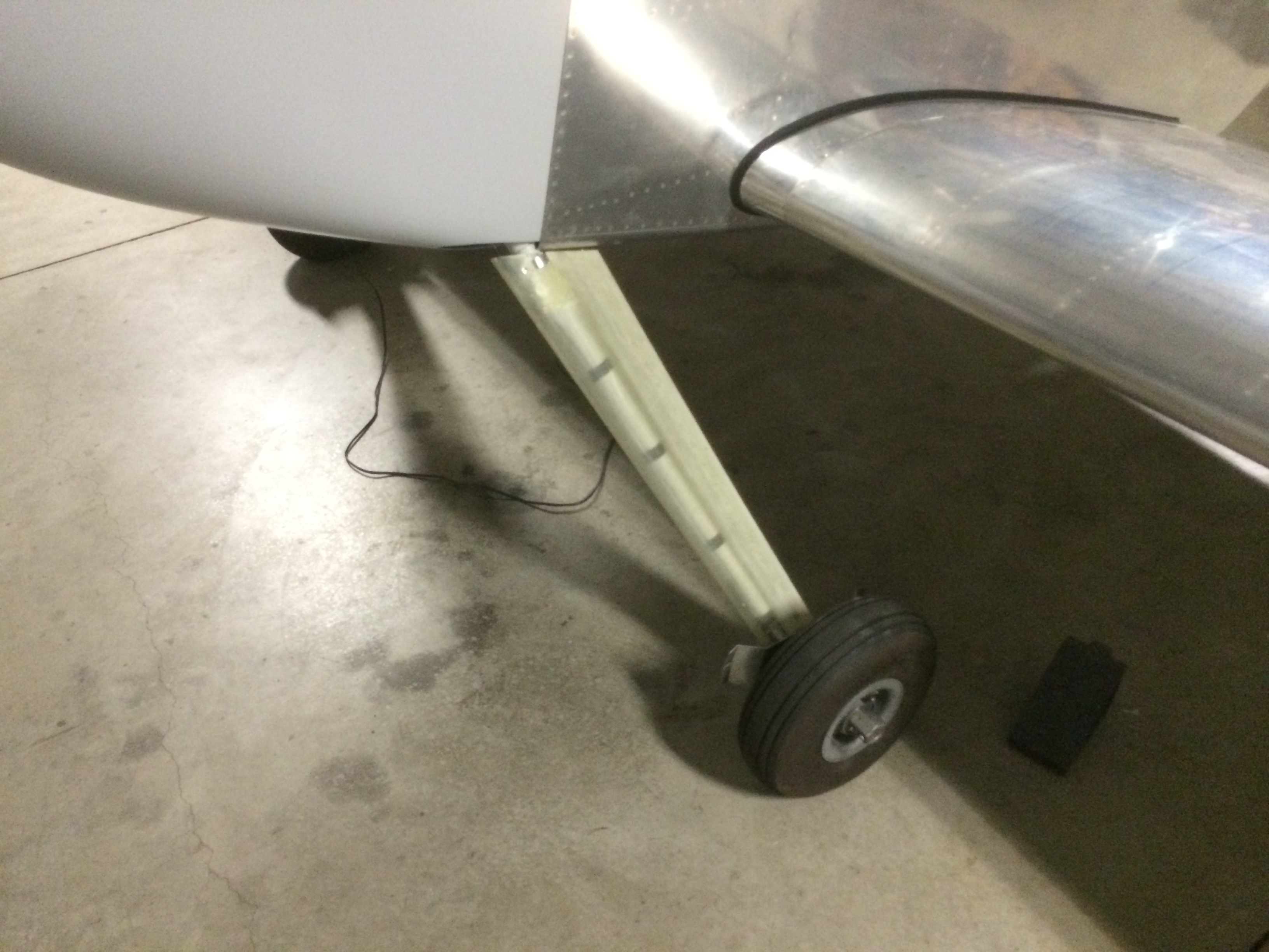
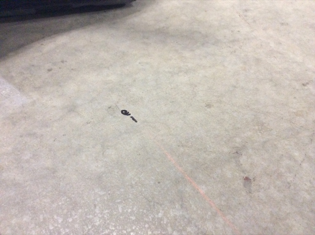
Before drilling the lower intersection fairings to the wheel pants, I needed to ensure the gear leg fairing is aligned.  I wrapped a piece of fishing line around the fairing and held it with a piece of blue tape.  I dropped a plumb bob down from the intersection of the fishing line and leading edge of the fairing and made a mark on the floor.  I measured out from the centerline and up to the fishing line so that I could make the fishing line exactly parallel to the aircraft centerline.

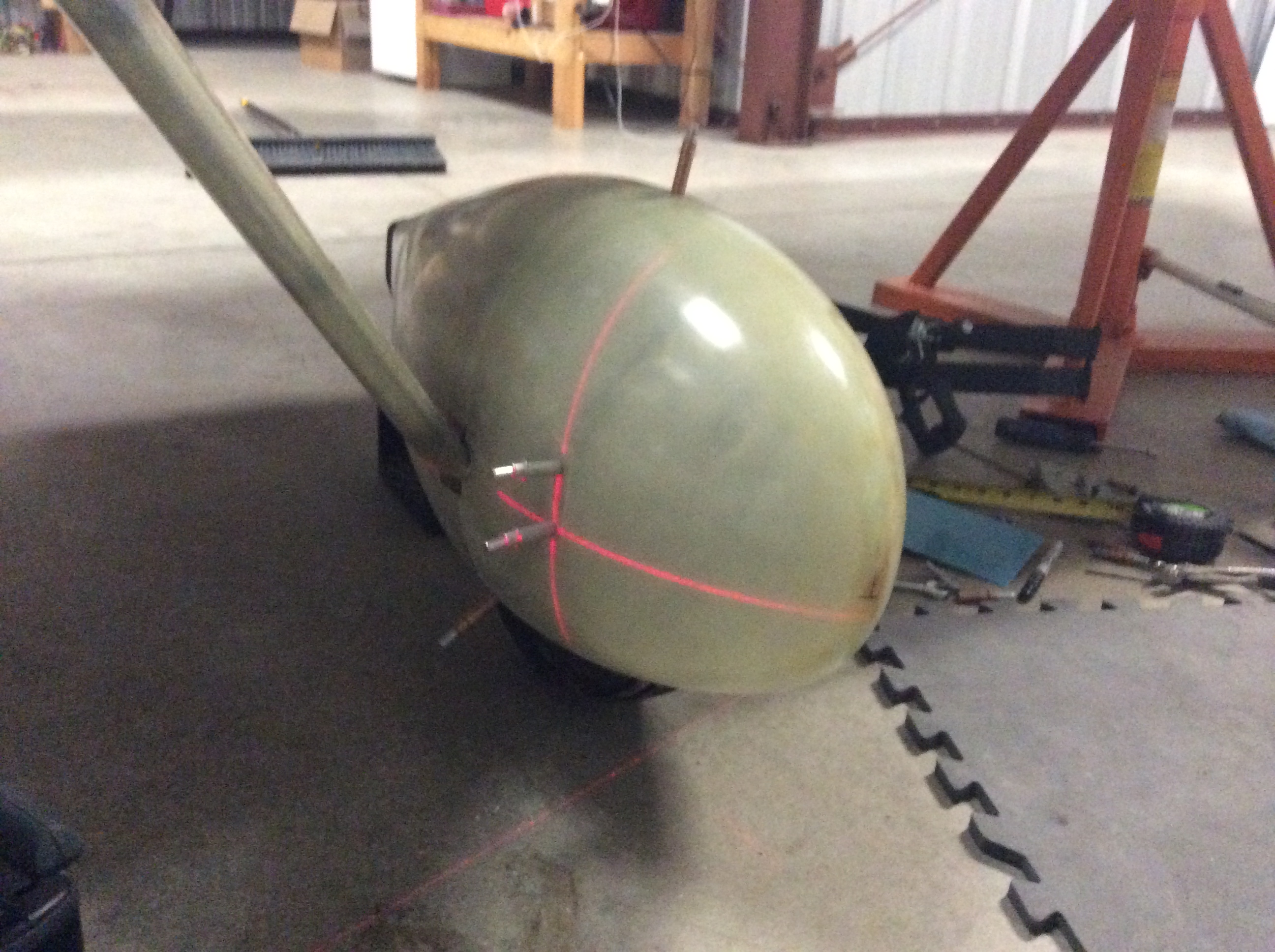
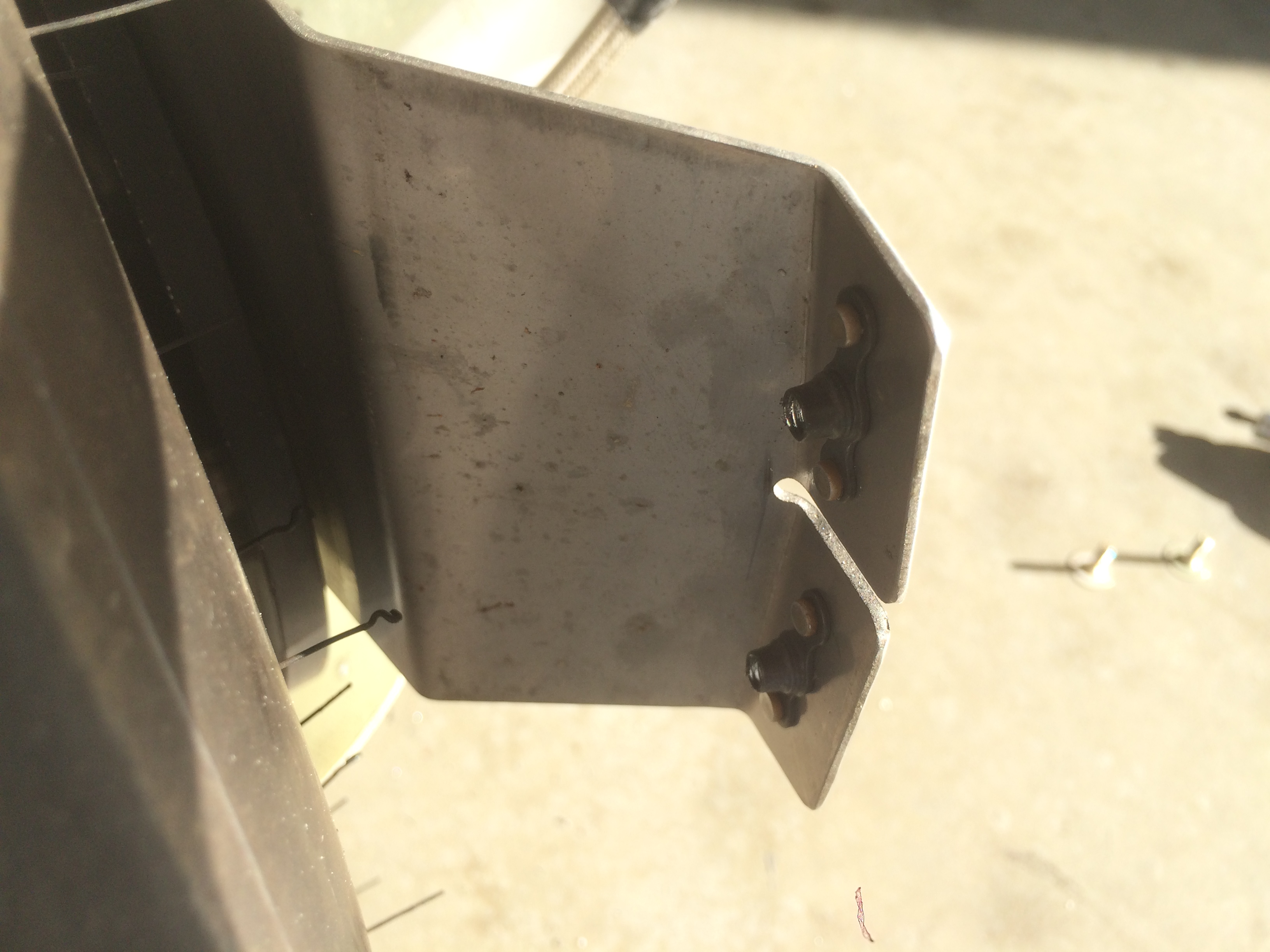
I transferred those measurements to a board that I positioned under the tail of the plane and then drilled a small hole at that position.  I ran the fishing line through the hole and tied it off to the tailwheel.

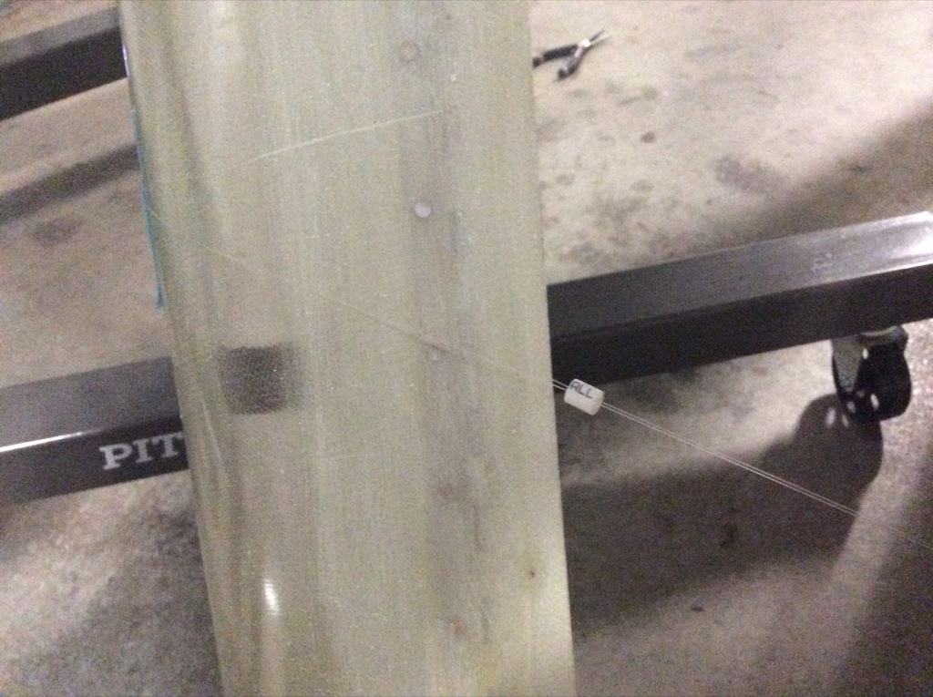
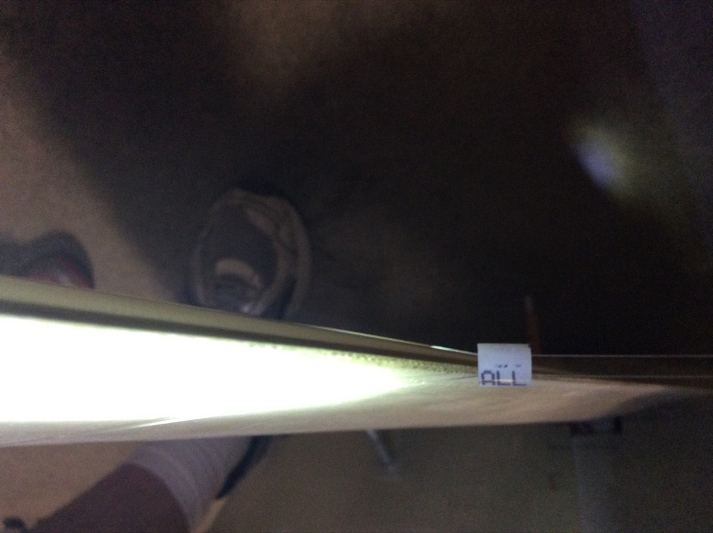
I slipped a small piece of static line over both lines and slid it close to the trailing edge of the fairing.  Amazingly, the left fairing was already perfect.  I had previously aligned it with the upper intersection fairing, but I didn’t expect it to come out this perfect.

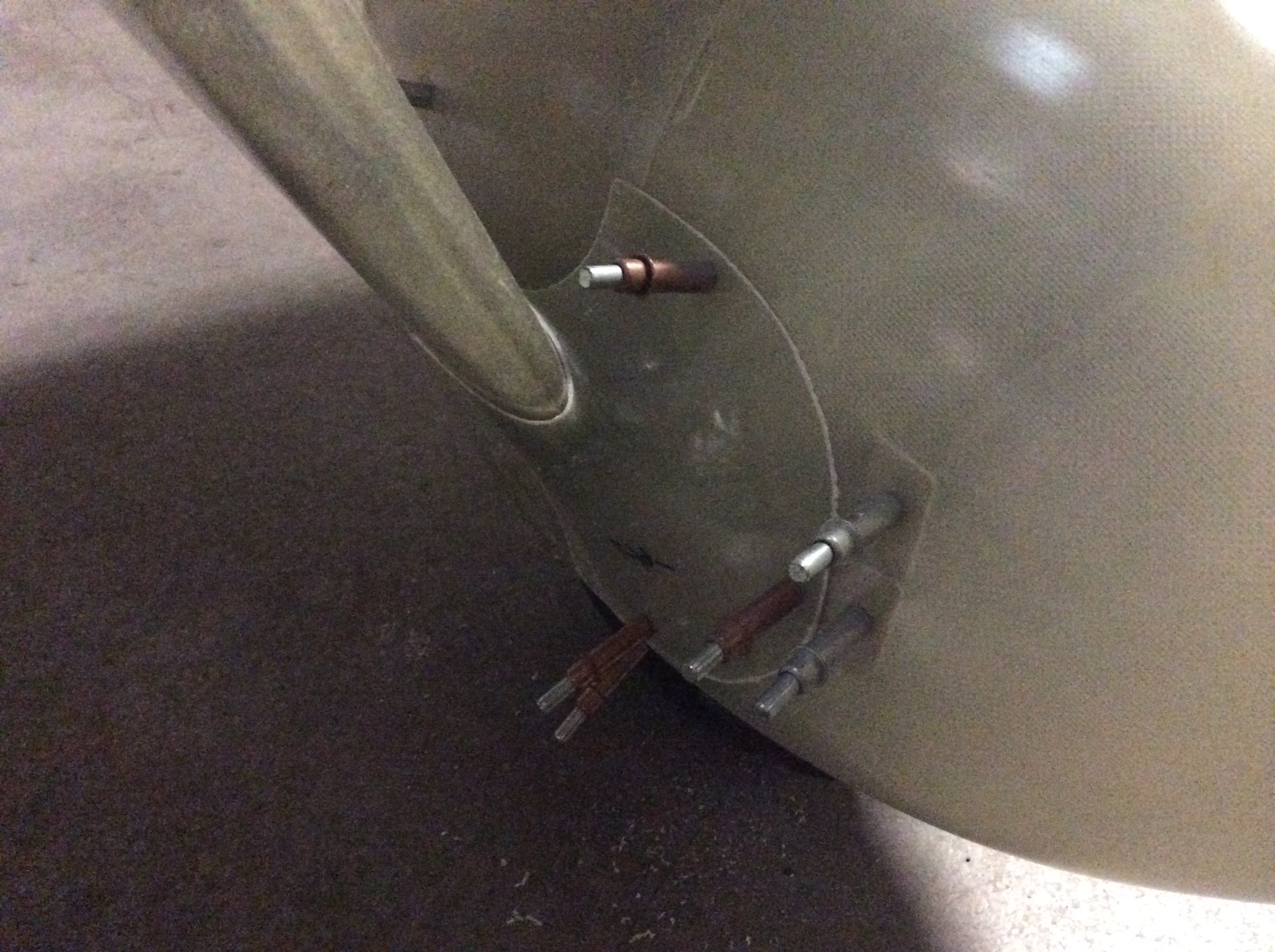
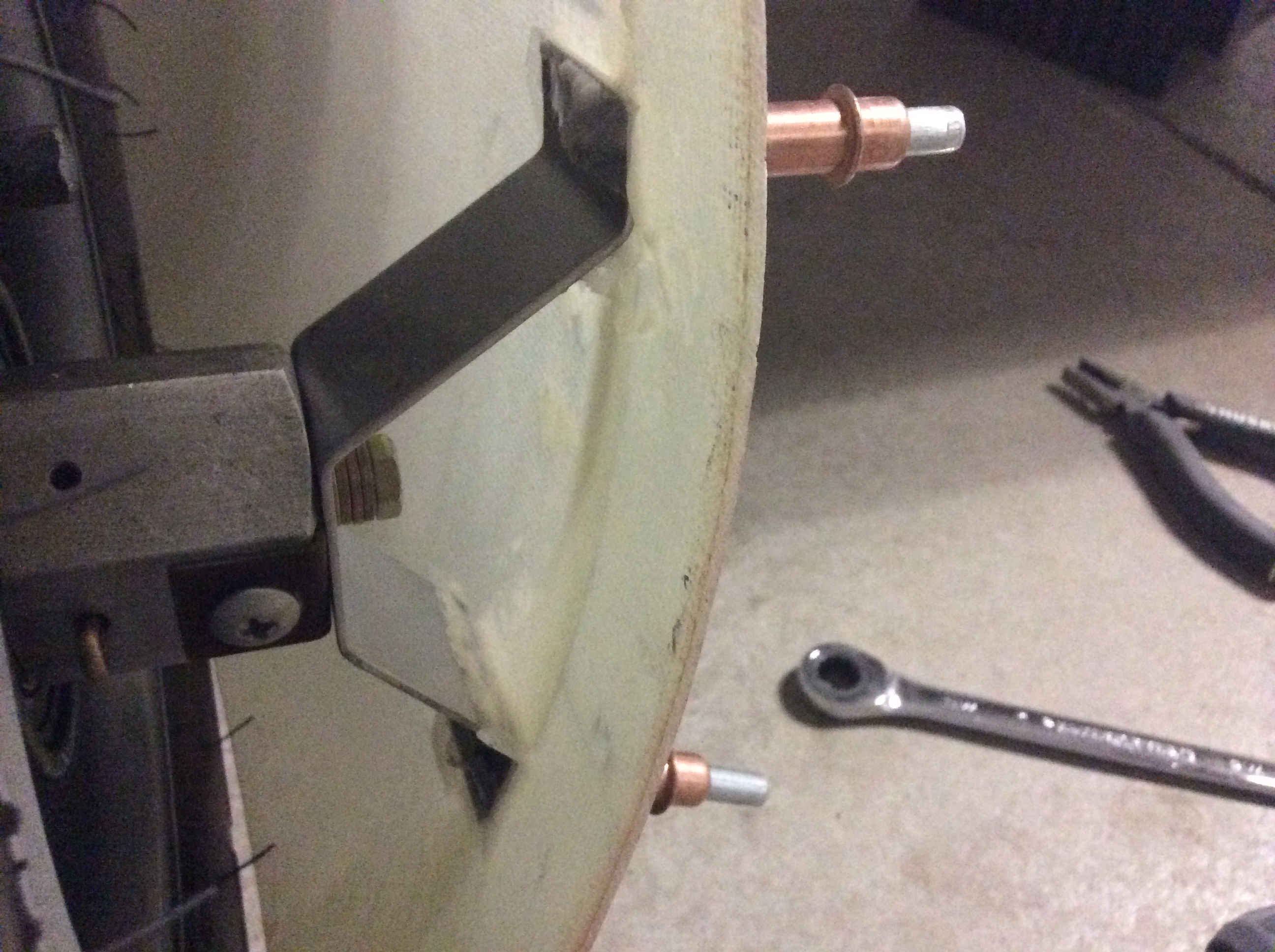
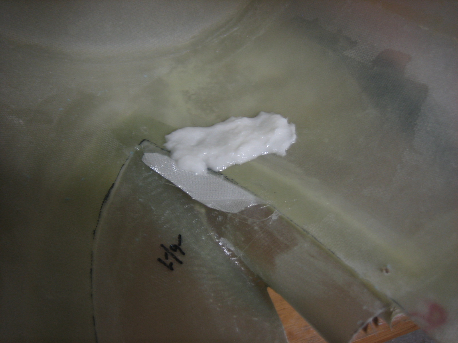
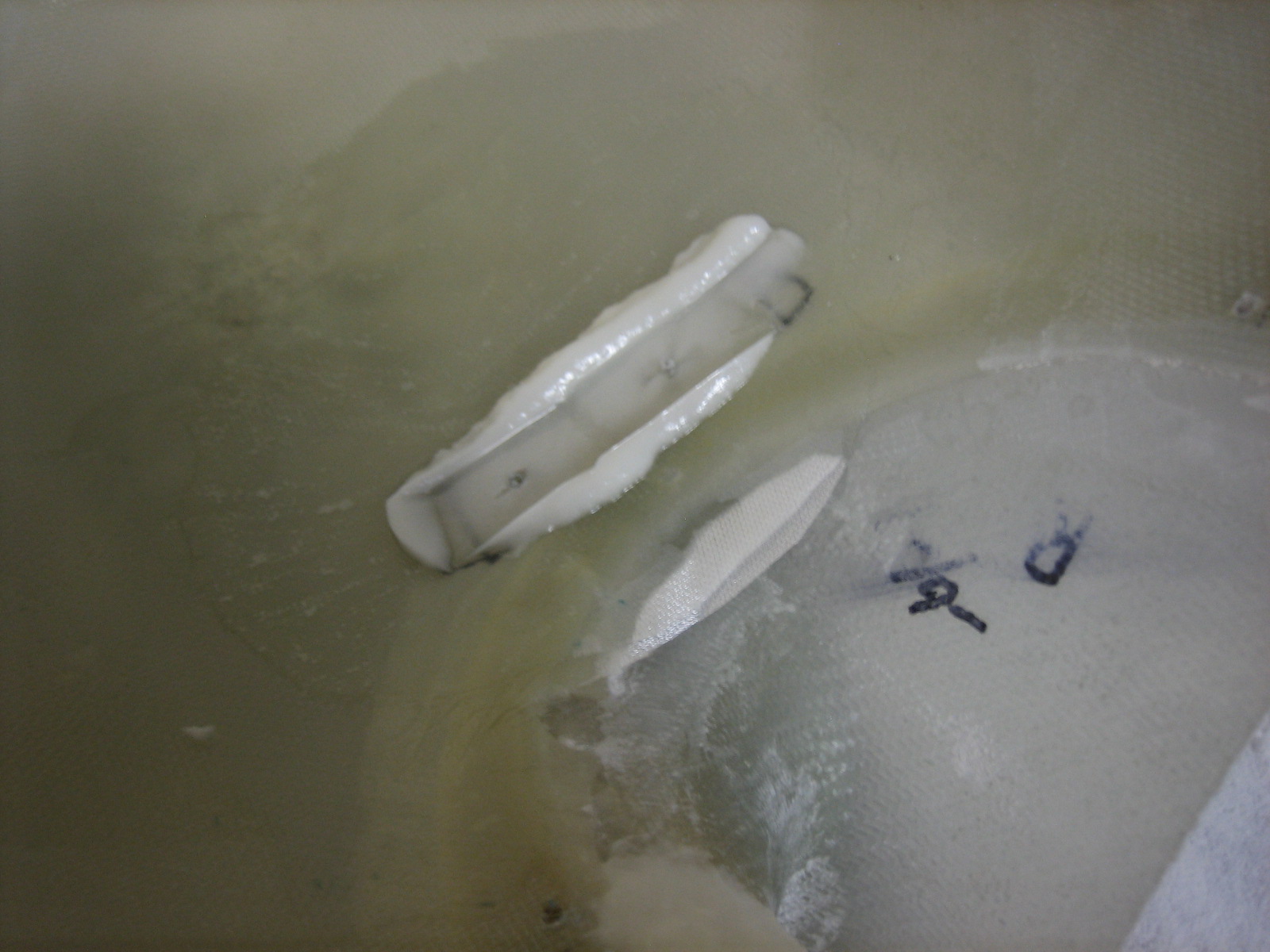
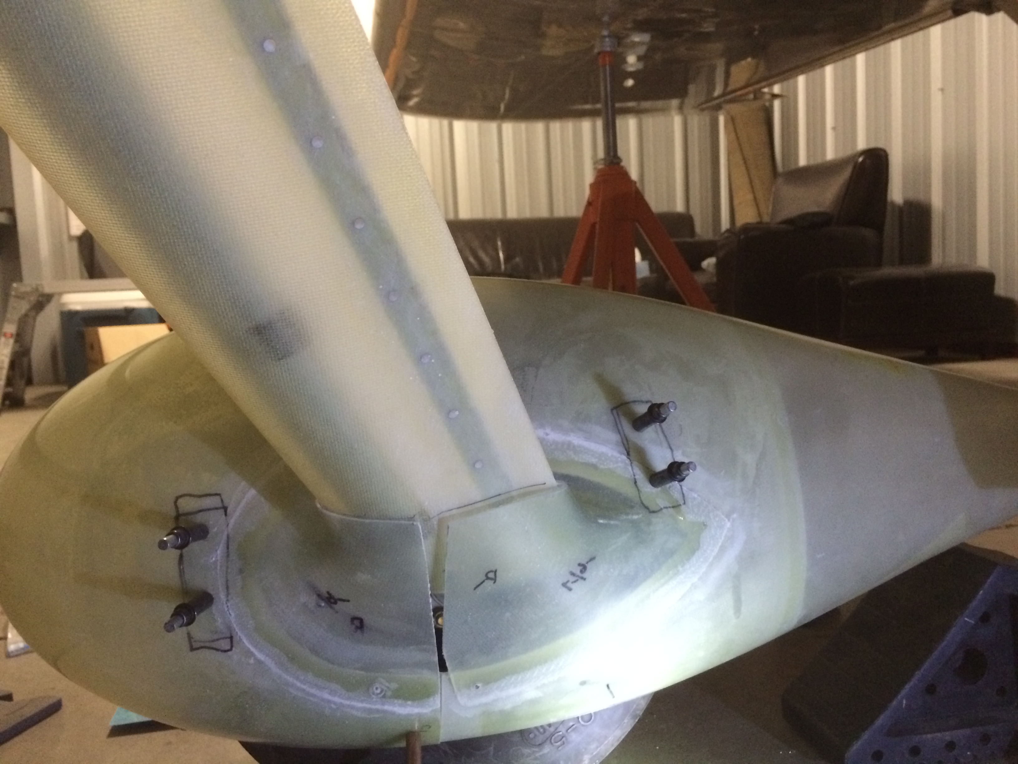
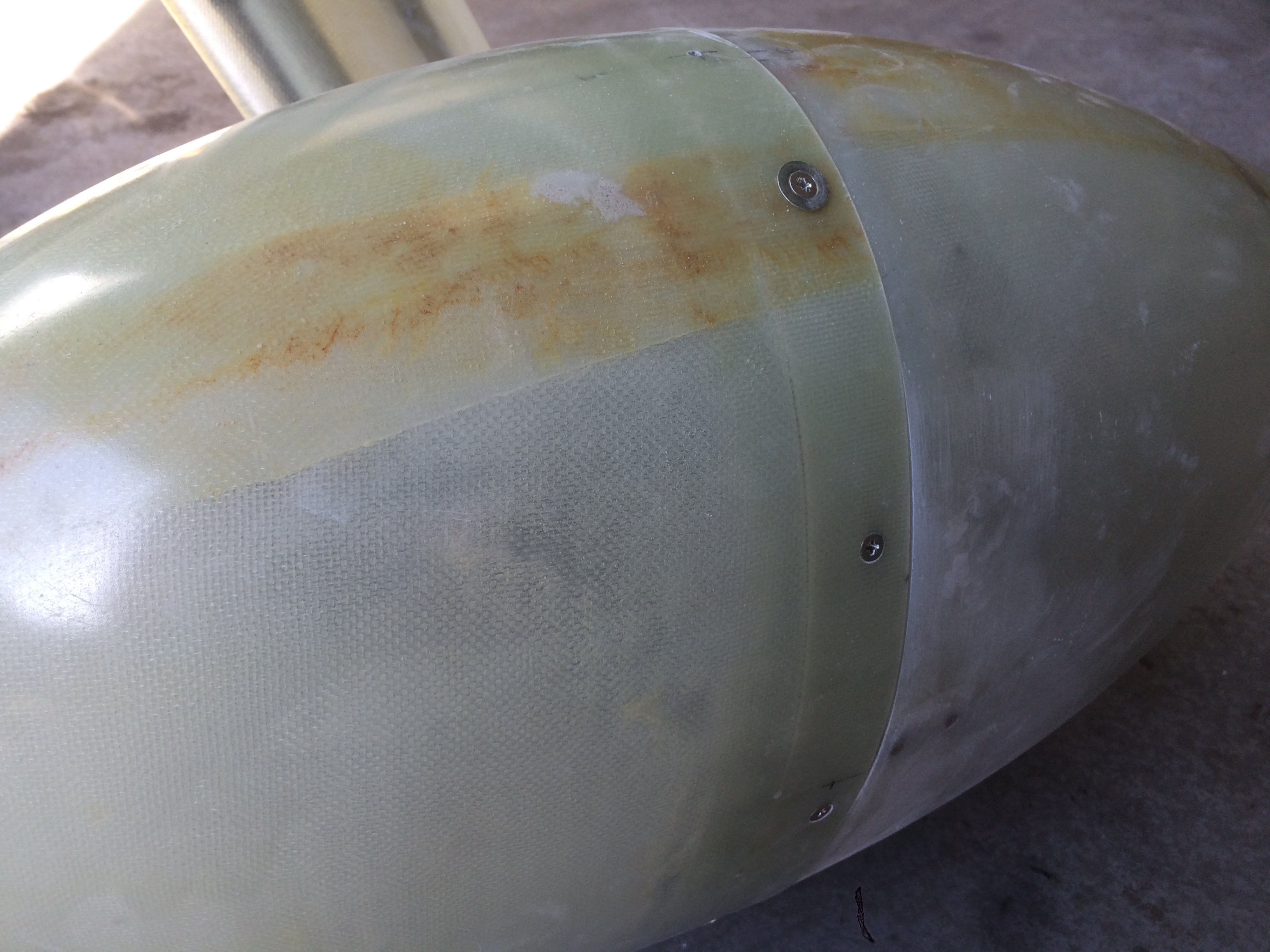
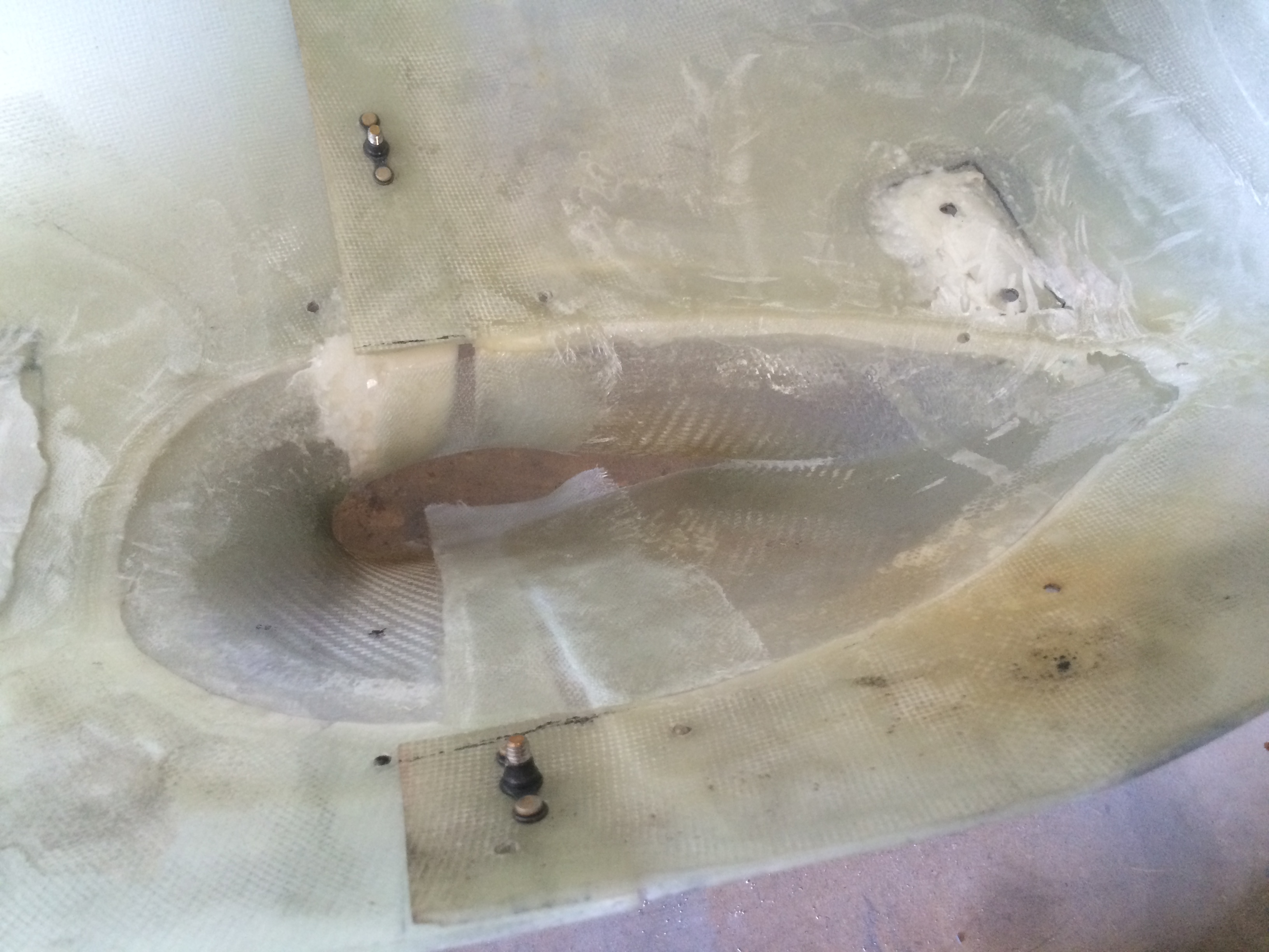
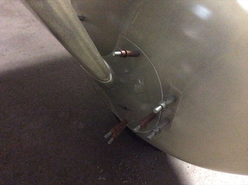
With the gear leg fairing aligned, I could install the lower intersection fairings to lock in the angle.  I drilled the front and back halves with several 1/8″ holes each.

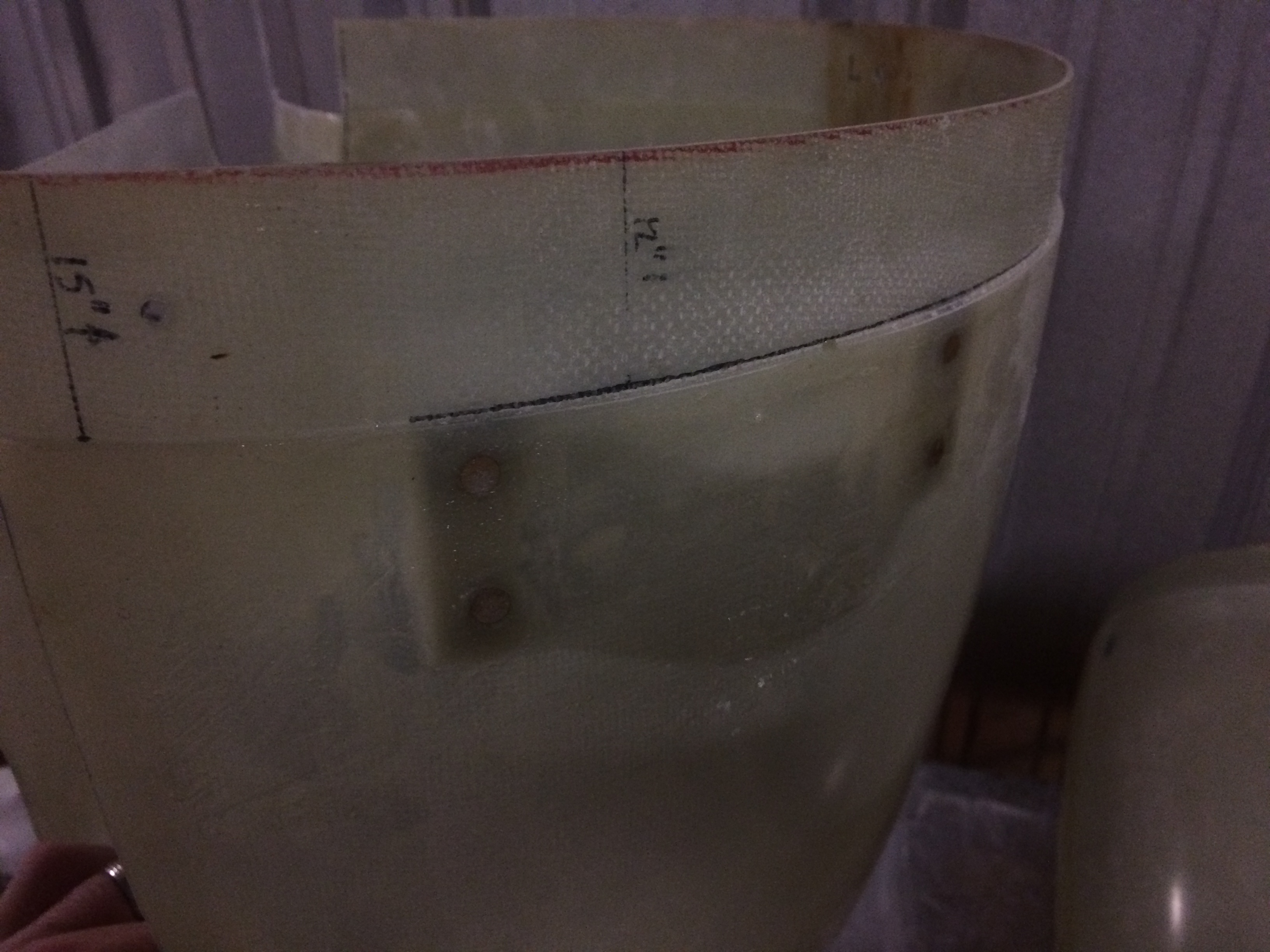
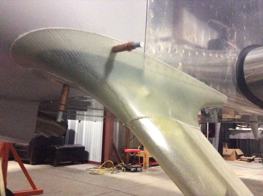
I then slid the upper intersection up tight and drilled a few holes to lock it into position.

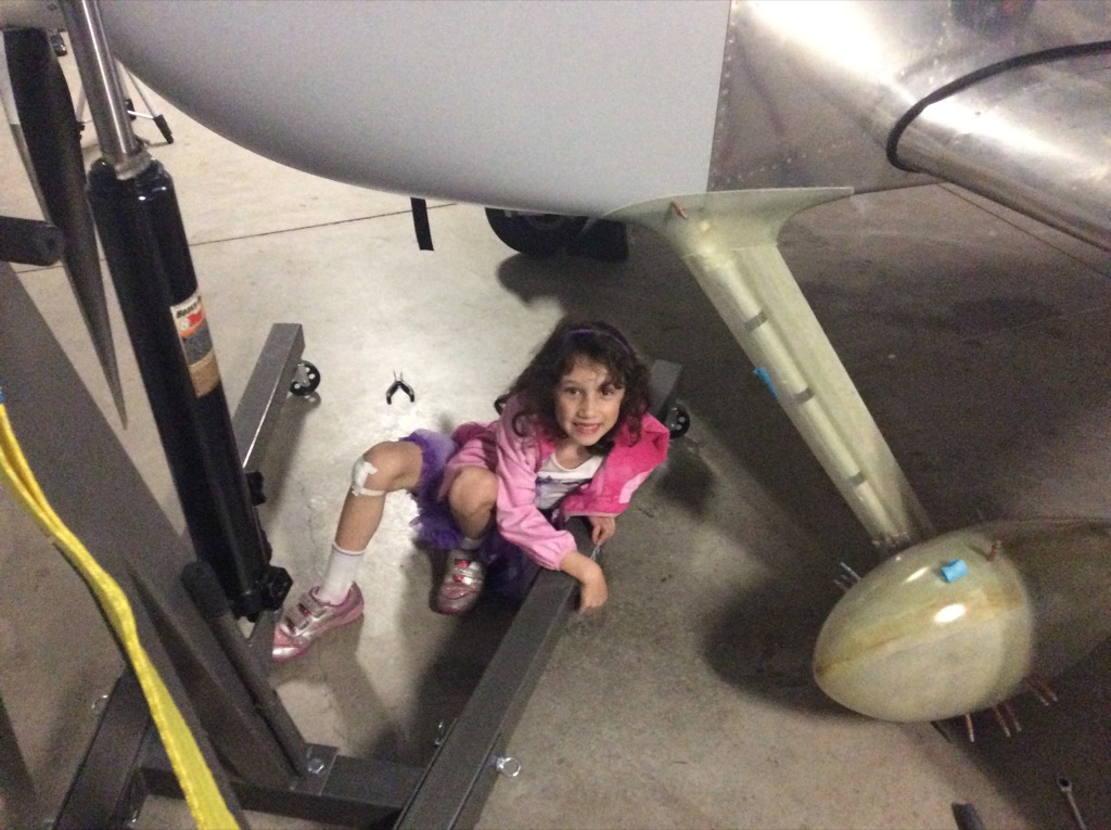
Madeline was a big helper today, bringing me tools whenever I needed them.

I wrapped up the other side and then took the plane back off the jacks.  Although the jacks are very stable, we live in earthquake country and I didn’t feel comfortable leaving it up on the jacks overnight.

Worked on Wheel Pants

I mixed up some epoxy/flox and glued the lower intersection fairings to the wheel pants.

After the epoxy cured, I trimmed the intersection fairings along the split line so I could fit the two halves together.  You can see that there are some gaps to fill.

The right side is much worse.  I’m going to have to build up the flanges since there’s such a large gap.

The wheel pants attach to the gear in three spots; the outer bracket shown here and an inner bracket that has forward and aft attach points.  Because the wheel pants are curved, the bracket flanges don’t conform nicely to the inside of the pant.  To fix this, I mixed up some epoxy/flox and applied some before clecoing the pant in place.  This will create a nice flat mounting pad for the bracket.  This bracket will be riveted to the pant and the others will get nut plates so the pant can be attached with screws.

I used some of the extra epoxy/flox to build up the upper side of the forward half of the lower intersection fairing.   I will need to sand away the other side of the fairing to align the front and back halves.

Riveted Outer Wheel Pant Brackets

I scuffed up the flanges and epoxy/flox shims, then used some epoxy on the mounting surfaces when riveting these outer wheel pant brackets on.

Here’s the outside.  I threw a layer of glass over the outside to prevent the paint from cracking around the rivets.

Glassed Inside of Wheel Pants

I added a couple of layers of fiberglass to reinforce the areas around the mounting bracket attach points.  I then added some flox to the epoxy and spread a reasonably thick layer over the area where the bracket will sit.  A bunch will extrude out, but it’s easier to grind off the extra than mix up subsequent batches because there were voids in the shims.

I taped over the mounting flanges, then reinstalled the wheel pants so that the epoxy/flox could set up in the right position.

You can see the extra flox through the wheel pant here.  I didn’t want to use clecos to clamp this while the epoxy cures because that would flex the mounting bracket and squeeze out the excess epoxy/flox.  Instead, I simply used some really long 3/32″ rivets to keep the holes aligned.  I’ll put the plane back up on jacks and realign the wheel pants while opening these holes up for screws since there could be some misalignment introduced as the holes are drilled out.

Trimmed Wheel Pant Mounting Shims

I popped the wheel pants off the plane, and all of the mounting shims turned out great.  There was plenty of squeeze out to ensure that the shims went to the edge of the mounting flanges.

I used my fiberglass cutoff wheel to remove the excess epoxy/flox and fair it into the surrounding glass.  I don’t care if this is perfectly smooth since it’s on the inside of the wheel pant.  I mainly just want to remove the sharp edges so I don’t cut myself when handling these in the future.  A lot of dirt and muck will get slung up into the wheel pants over time, so I want to make this reasonably easy to clean if necessary.  Finally, I reinstalled the wheel pants in preparation for final alignment.

Final Wheel Pant Alignment and New Avionics

I put the plane back up on jacks and slowly enlarged the mounting holes up to #19 for a #8 screw while adjusting the wheel pants to be perfectly aligned with the longitudinal axis of the plane.  They were off a little bit when I started which is probably due to the epoxy/flox shims slightly shifting the position of the pants from when I first drilled them.  Since my brackets are stainless steel, I needed to use a fair amount of pressure to drill these, so I backed them up with some wood to prevent them from flexing in as I drilled.

After drilling these out, I pulled the wheel pants and gear leg fairings off the plane and to the plane back off the jacks so it’s ready for flight again.

Dynon recently released two new boxes that work with the SkyView system: one to provide dedicated knobs to control the altitude bug, heading/track bug and barometric pressure and another to provide a set of dedicated autopilot controls so that you don’t have to navigate through various menus to control it.  I’m mounting these in my radio stack with the outer edges flush with the other boxes in the stack.  This leaves enough room in the center for another small device if I want to add one.  I laid out for the holes, but it was too late to start cutting into the panel.  Once I have these mounted, hooking them up to the SkyView network will be pretty straightforward since I can just daisy chain them between the displays.

More Work on Wheel Pants

I had another chunk of time today at the airport, so I decided to make a little more progress on the wheel pants.  I first drilled and mounted all of the nutplates on the mounting flanges.  These are stainless, so drilling them is a pain.

I also added 7 nutplates around the flange where the forward and aft halves of the left wheel pant join.  I also iterated a bit on the opening around the tire.  I now have 5/8″ of clearance all the way around with the weight on the tire.

With the pant attached to the mounting flanges, the left wheel pant is ready for flight.  I still have 2-3 hours of work to get the right pant to this stage, but then I’ll be ready for flight with these.

Adjusted Wheel Pant Brackets

I took the plane up for the first test flight with the wheel pants installed.  Everything seemed solid and the ball was still centered, so I guess I did a good job with the alignment.  On the taxi back however, I heard a funny sound coming from the wheels, so I pulled the wheel pants to see what was up.  I took a close look at all of the components and it was apparent that the bracket was being flexed into the brake rotor when the pants were installed.  I pulled the wheel and the bracket to take a better look.  You can pretty clearly see the mark that was being left on the bracket.  Fortunately, since this was stainless steel, the damage barely penetrates the surface and should be easy to remove.

The worst spot is right here and is still probably less than 10% of the thickness of the part.

You can see that the bracket was also damaging the brake rotor.  Since these are both steel, it looks like galling.

I used the scotchbrite disk to remove the marks from the bracket and then added an additional washer to push the bracket out an additional 1/16 of an inch.

I reinstalled the wheel pants and snaked an inspection camera inside to make sure there was still clearance between the bracket and the brake rotor.  Everything looked good, so I took it up for another test flight.  Problem solved.

Worked on Lower Intersection Fairing Flanges

I needed to create some overlap on the flanges of the lower intersection fairings to prevent them from lifting in the slipstream, so I taped up the forward flange and then laid up some glass over the joint so it will bond to the aft flange.

On the right forward pant, I needed to extend the flange before I can create the overlap.  I taped up a piece of thick paper and then attached it to the flange.  I then laid some additional glass over the paper to form the extended flange.

I ordered a set of cowl inlet plugs from Bruce’s Custom Covers.  They look great and fit like a glove.