Rigged Elevators

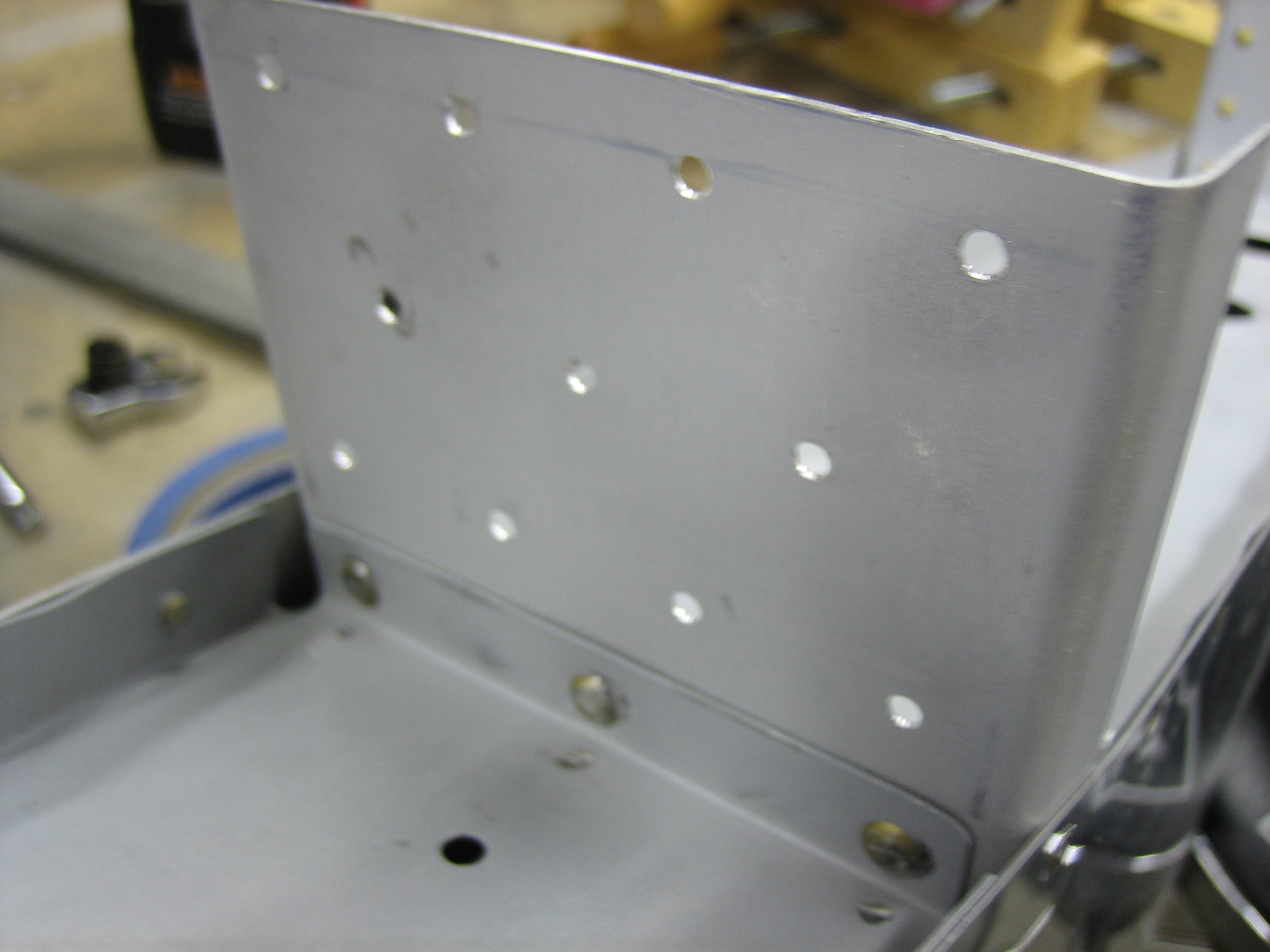
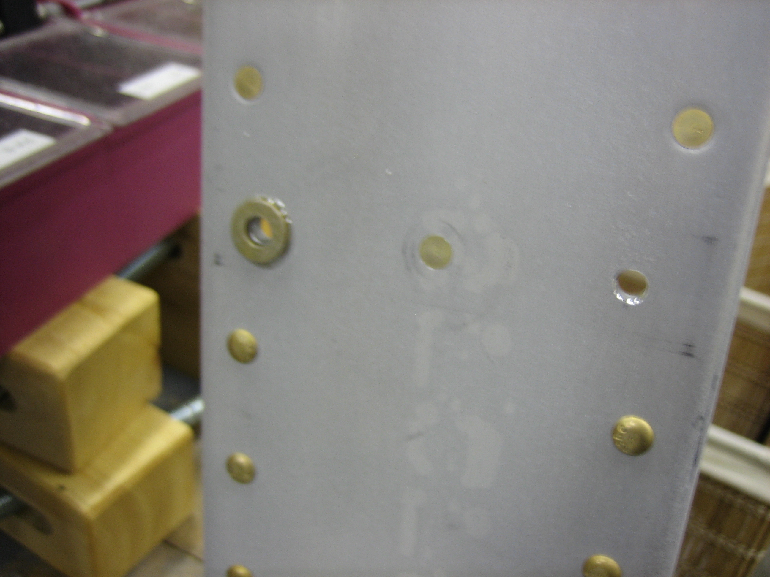
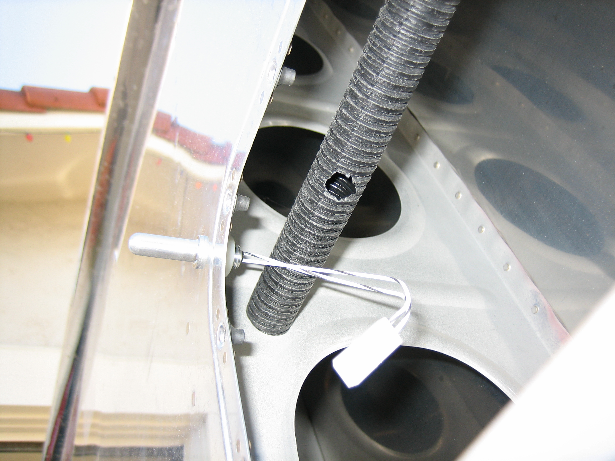
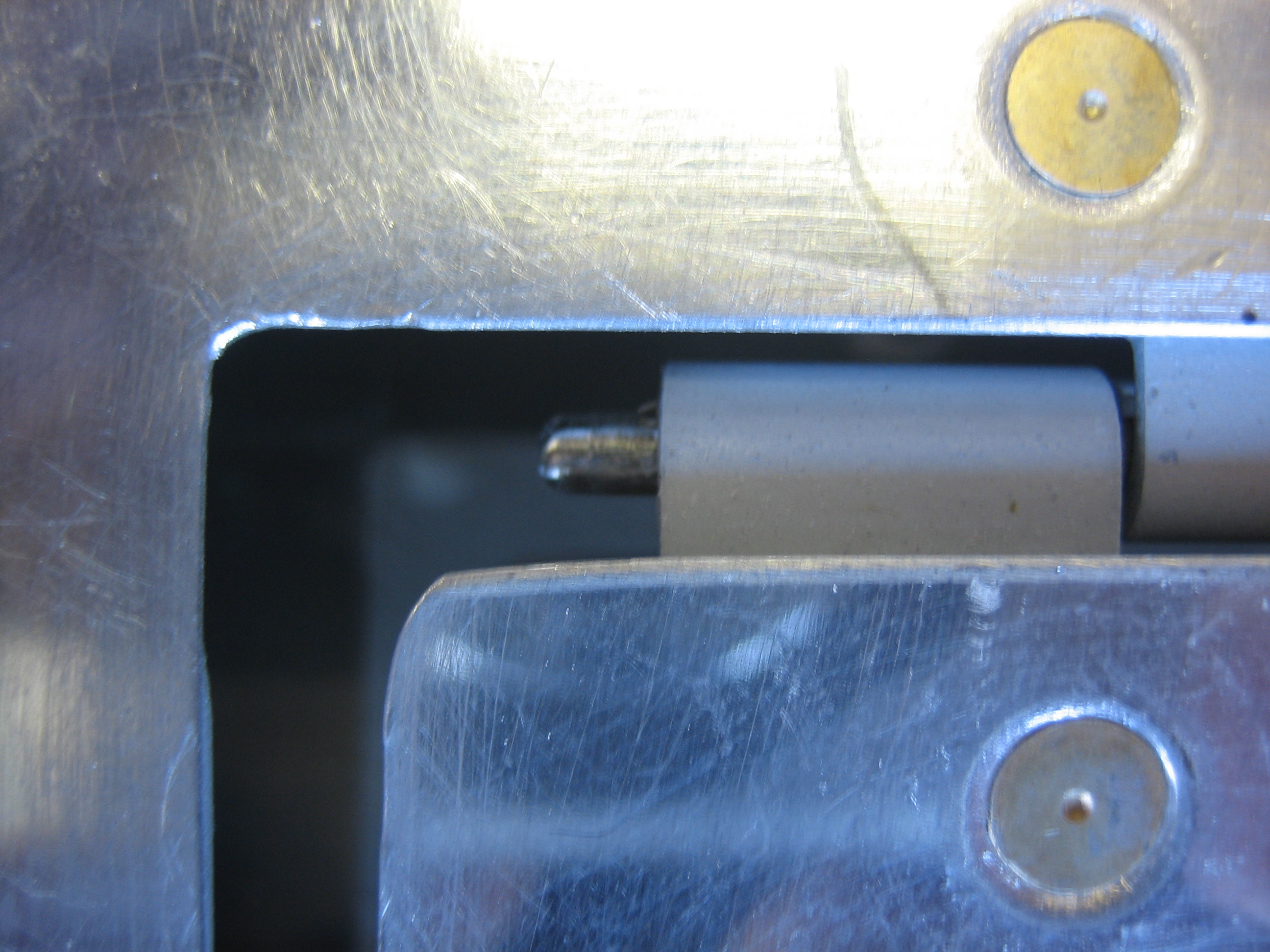
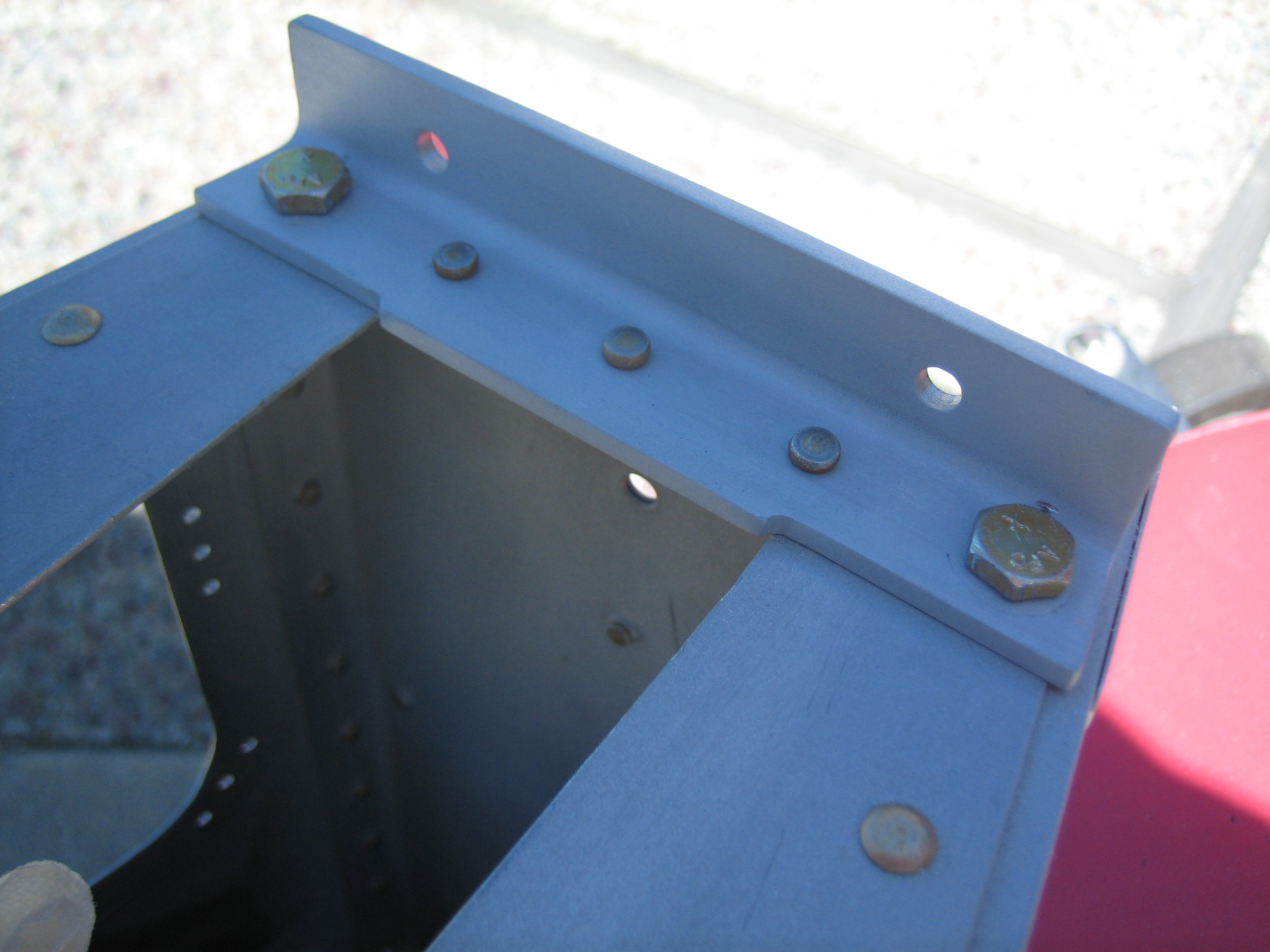
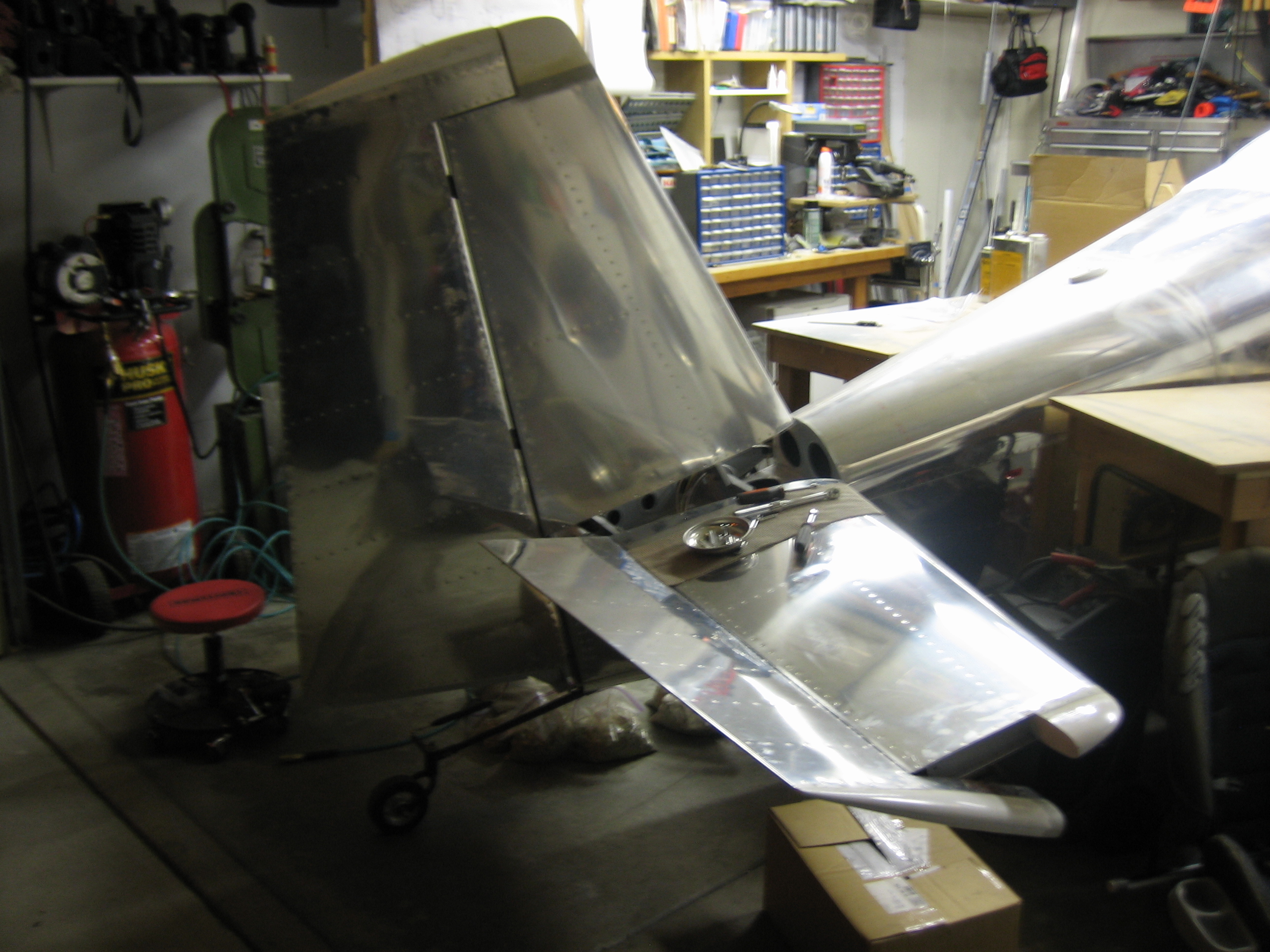
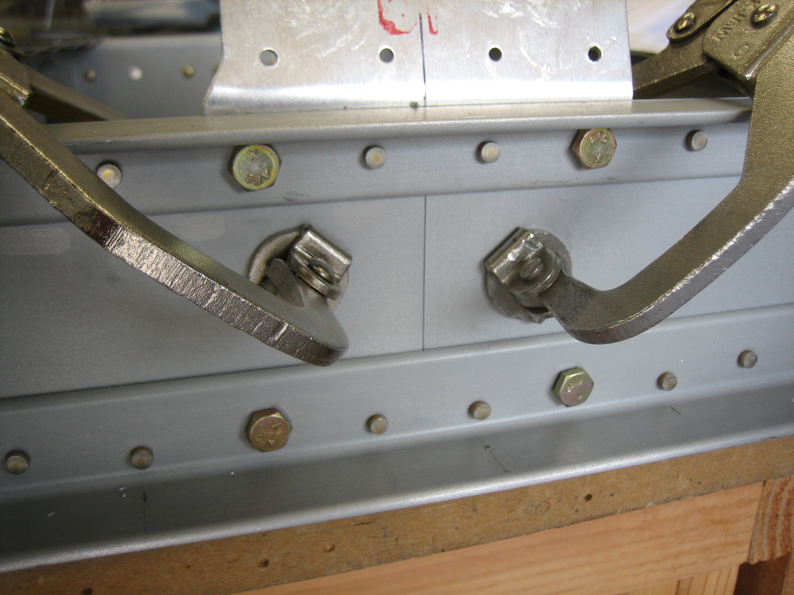
I finished drilling the aft deck and longerons to the elevator up stop.

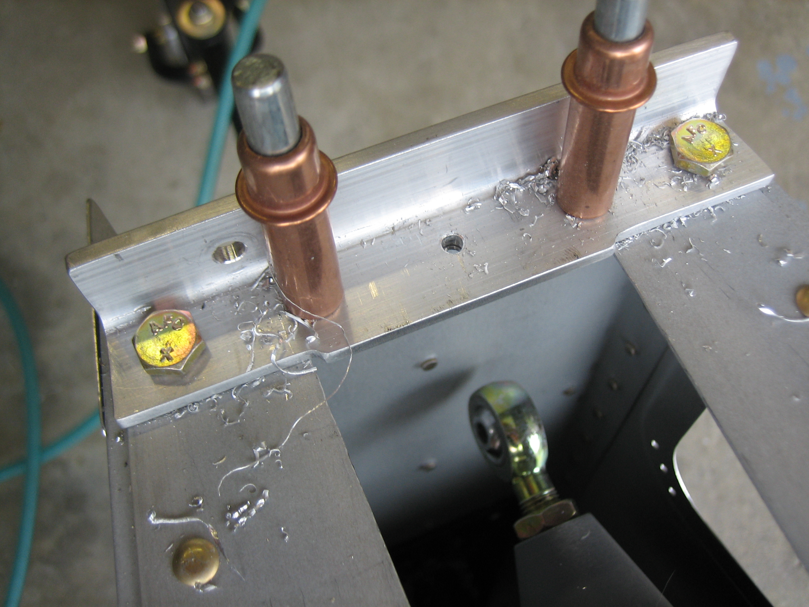
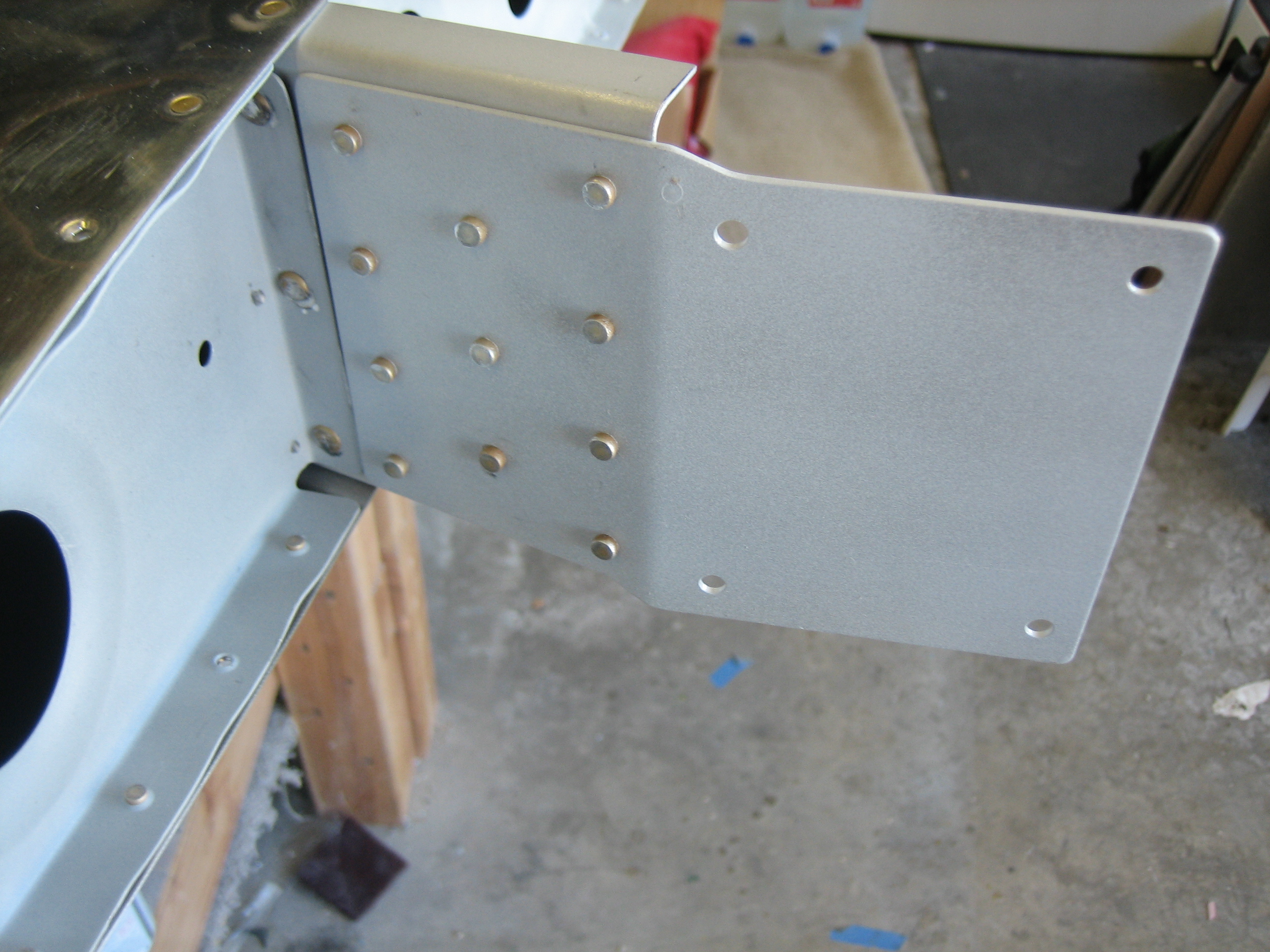
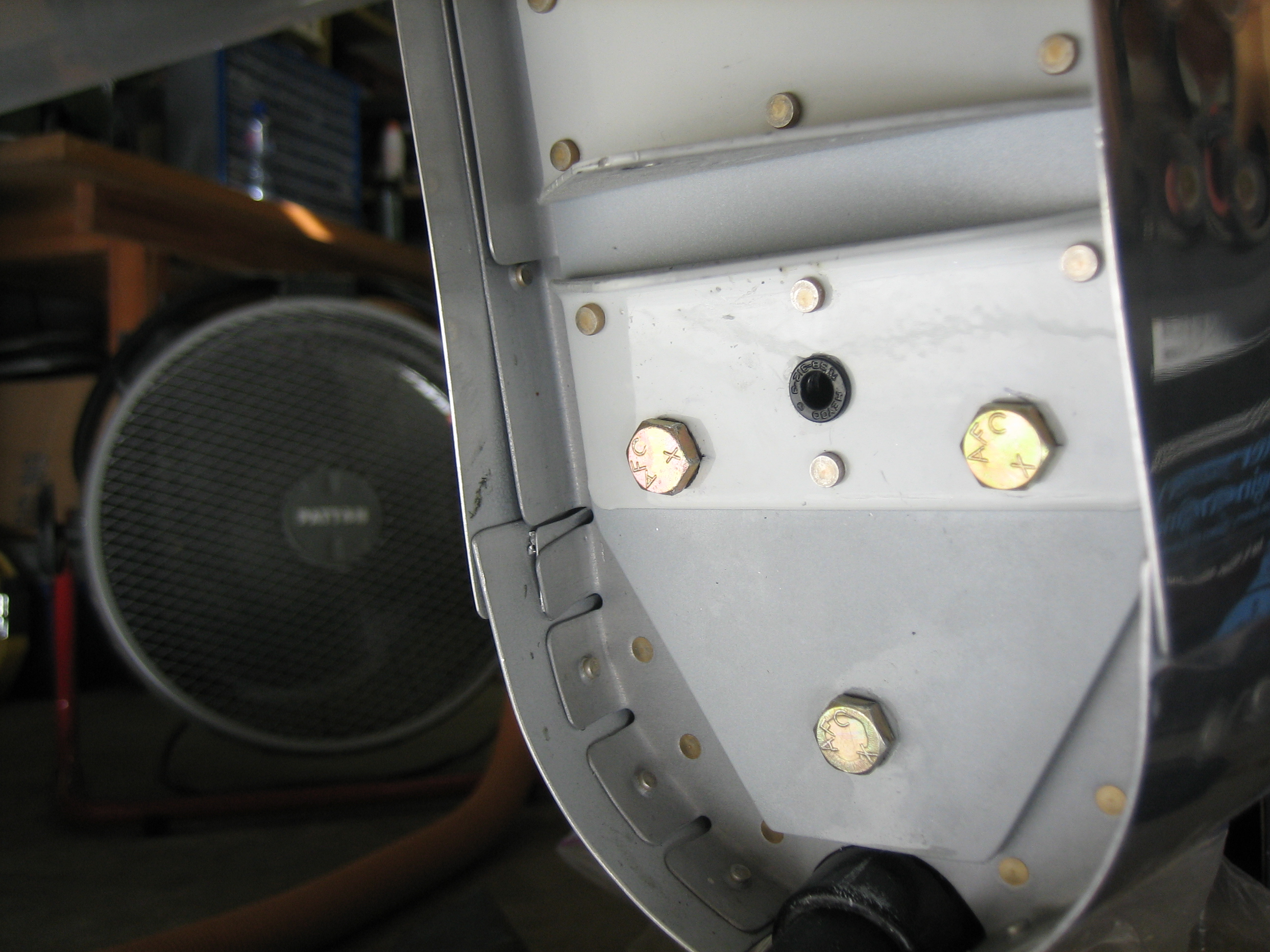
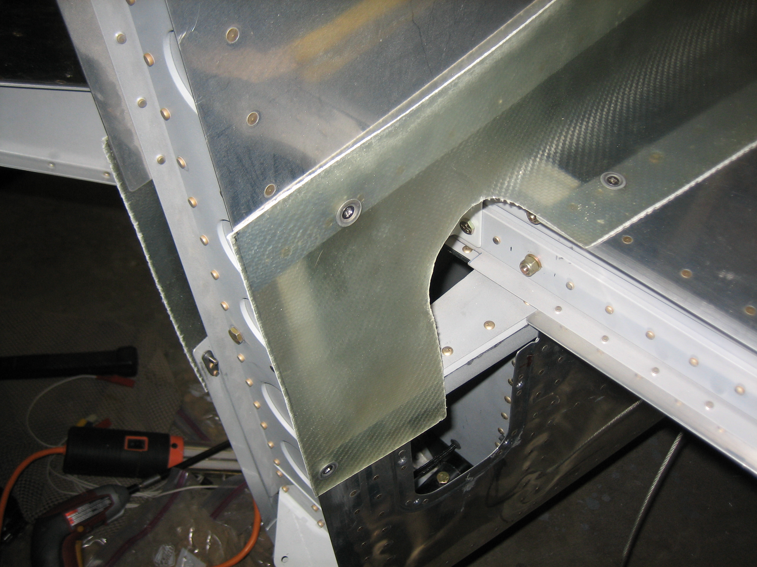
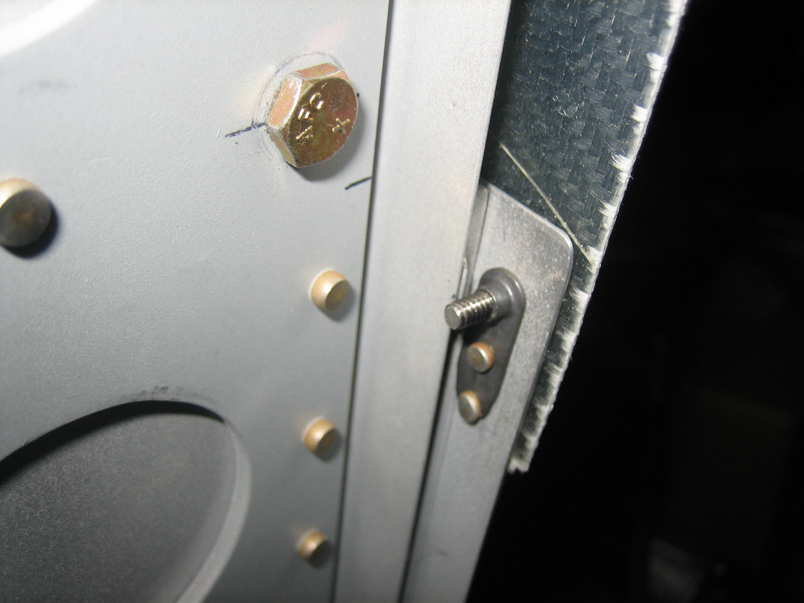
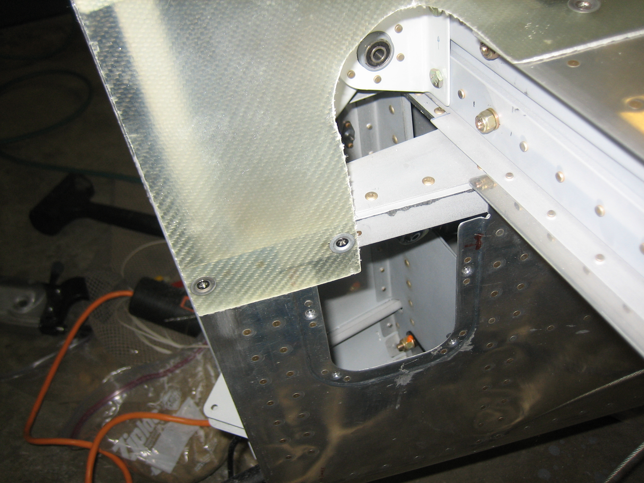
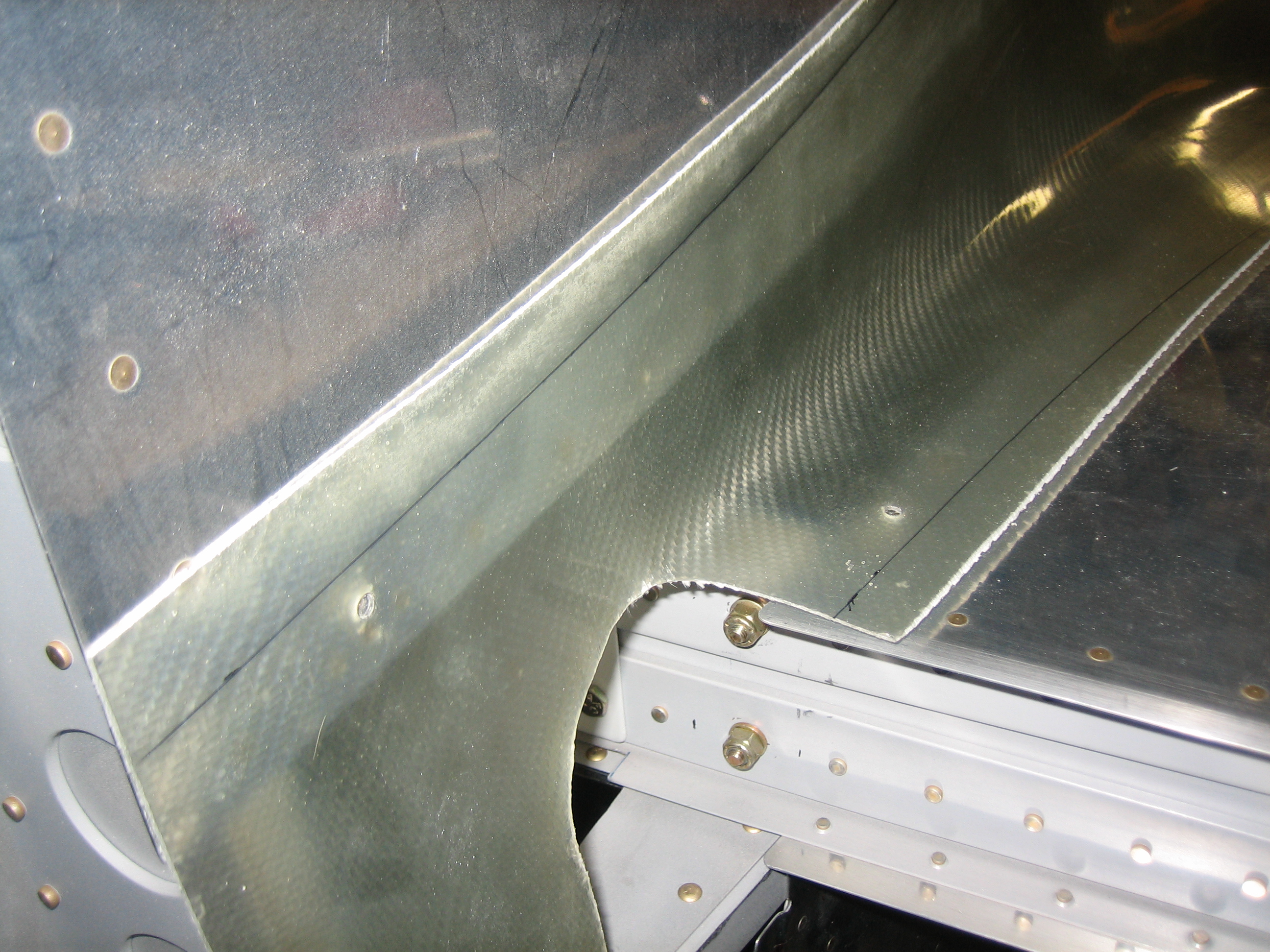
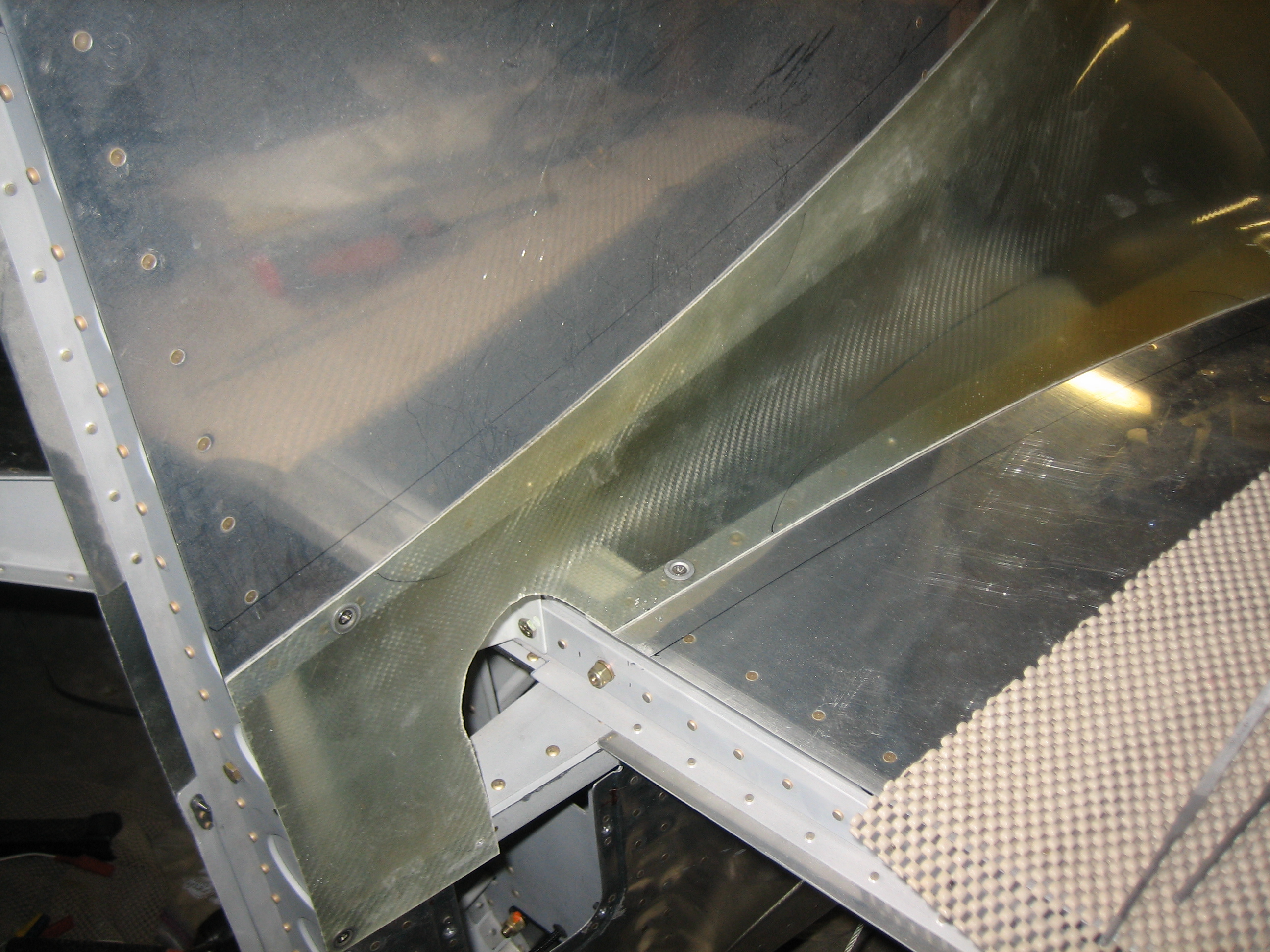
I also finished drilling/reaming the forward vertical stabilizer support bracket to the forward spar of the horizontal stabilizer.

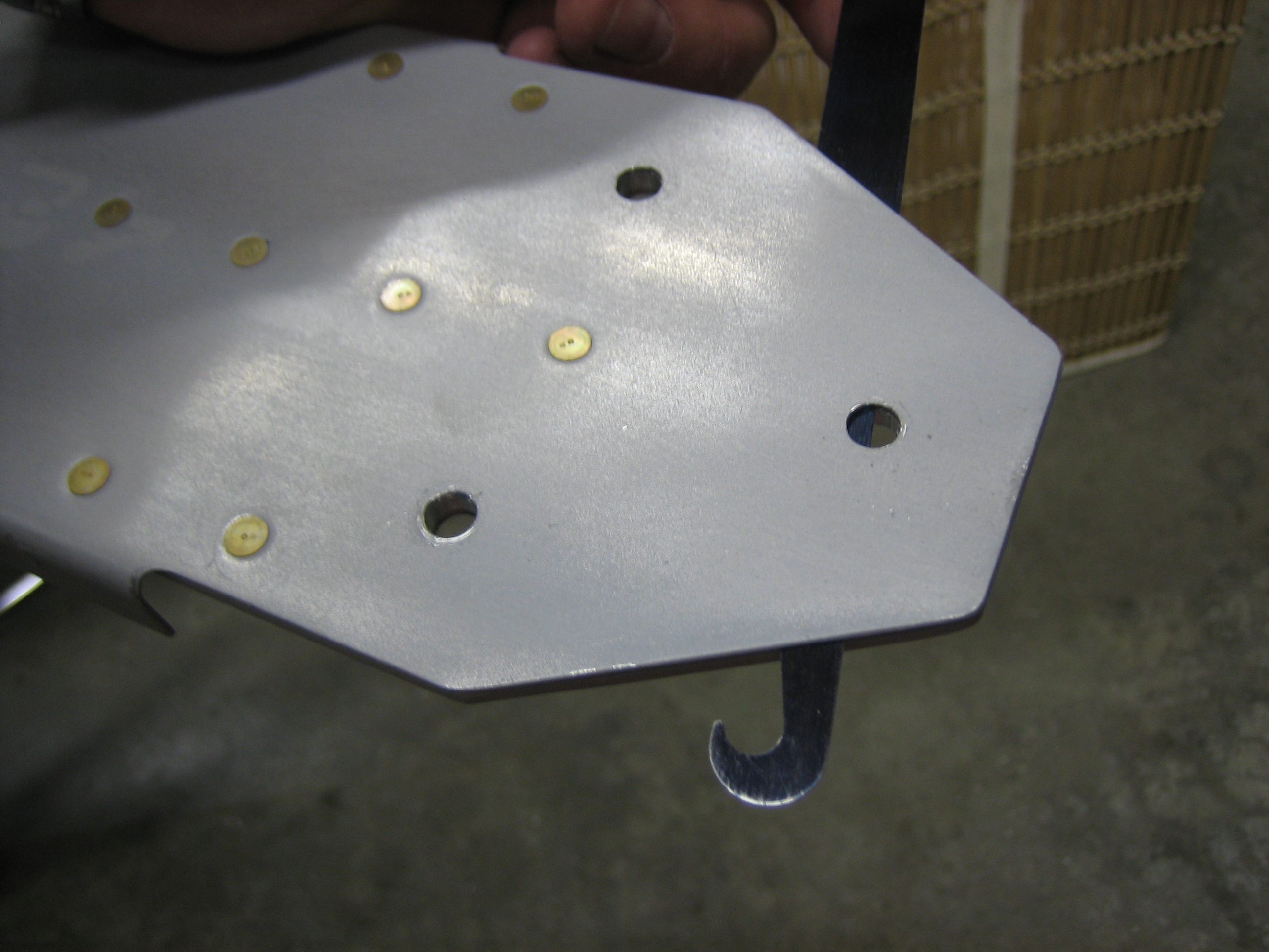
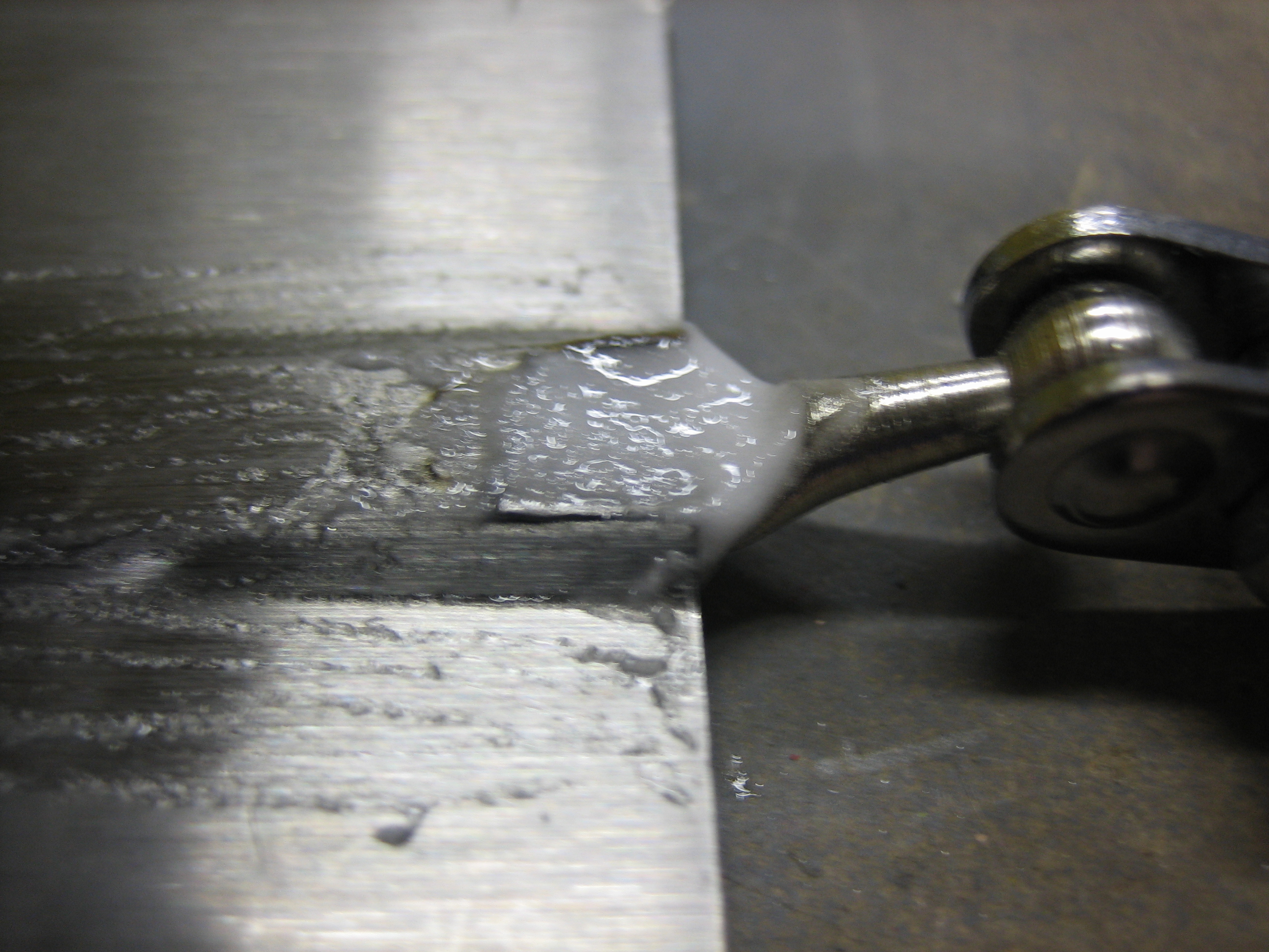
The elevator down stop needed quite a bit of material removed to achieve the recommended amount of deflection.

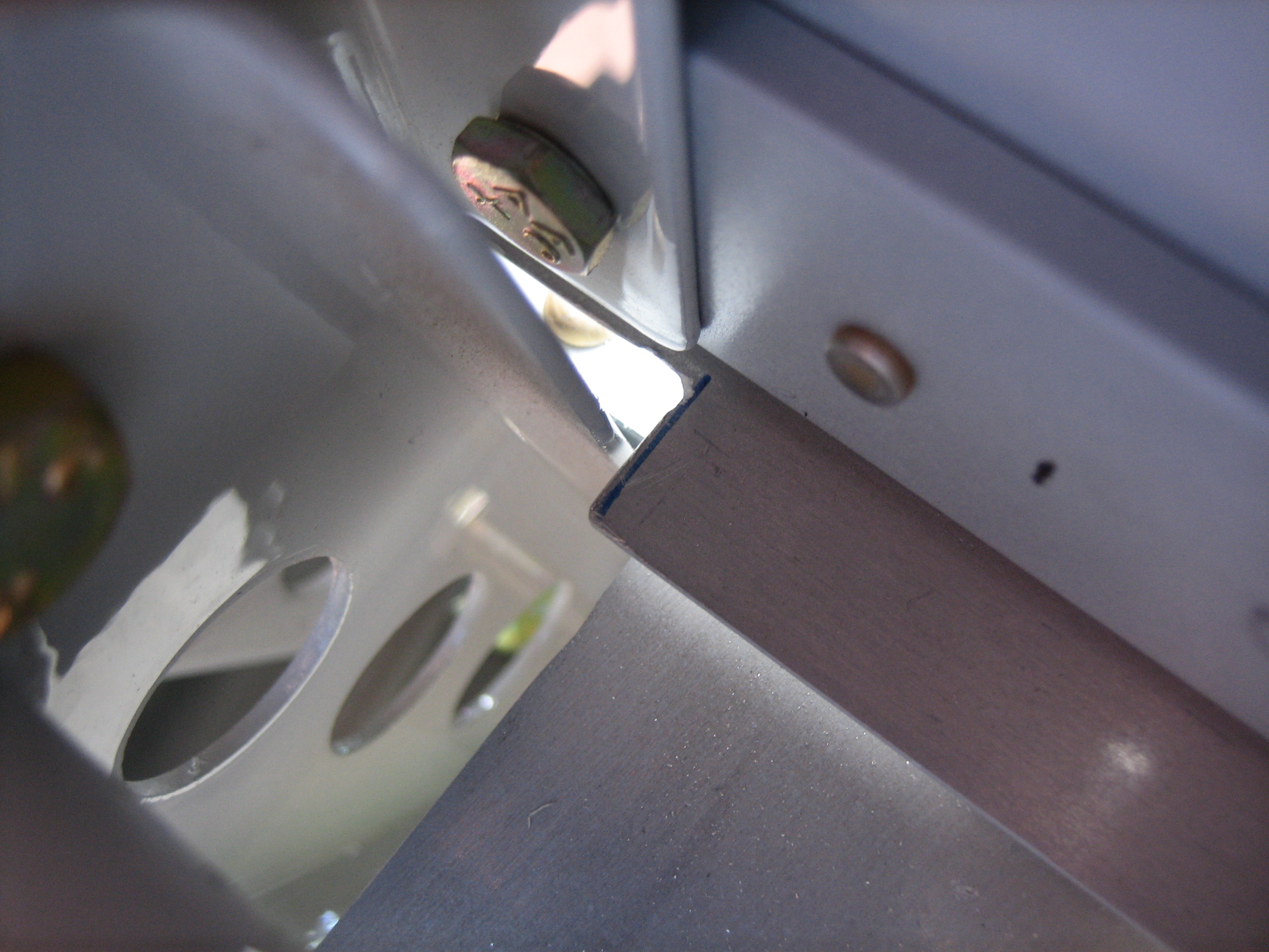
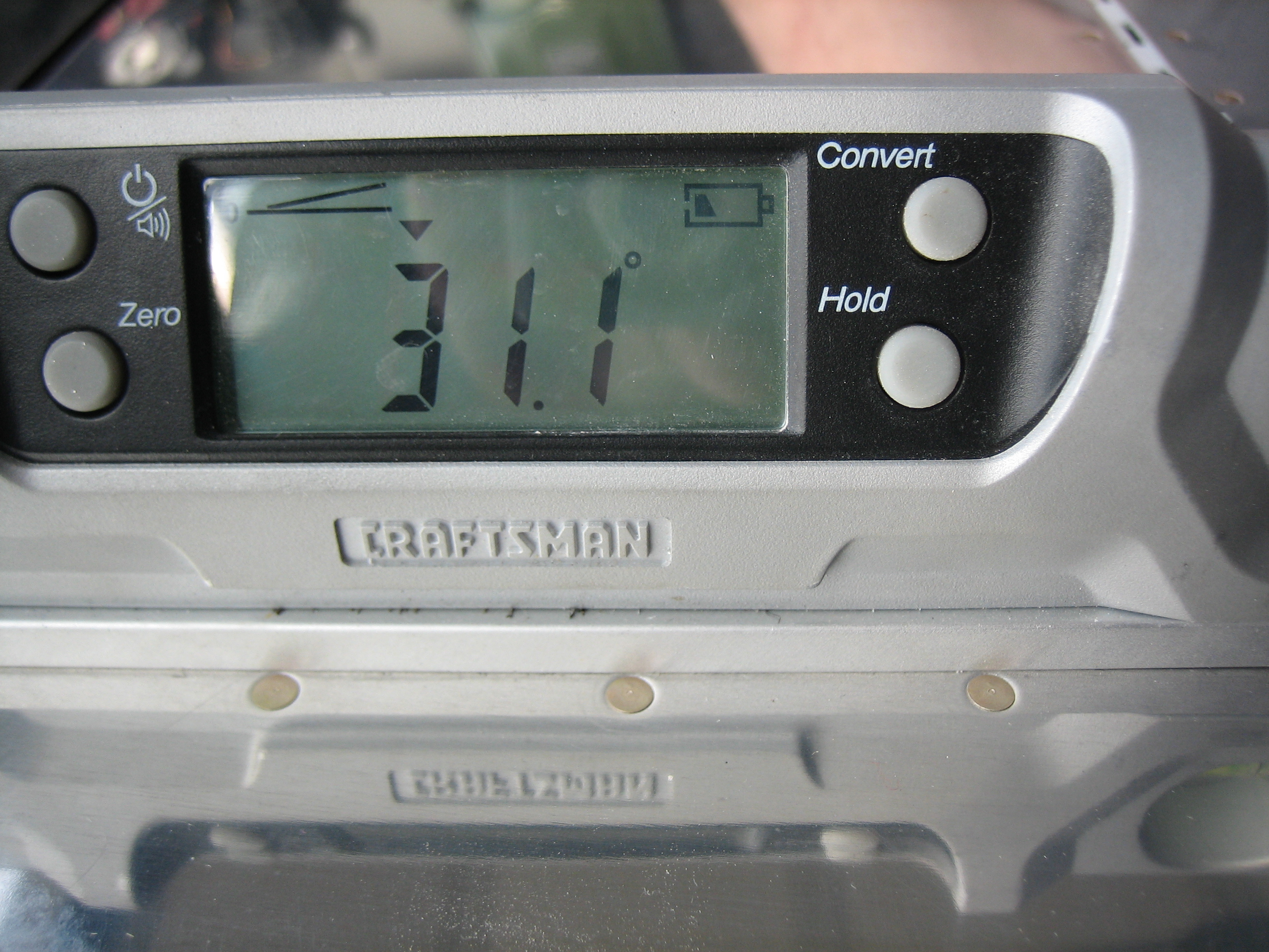
With the up stop manufactured to plans, I get 31.1º of upward deflection (25º-30º is the specified range).  It looks like a number of builders have ended up with slightly more than the 30º limit.

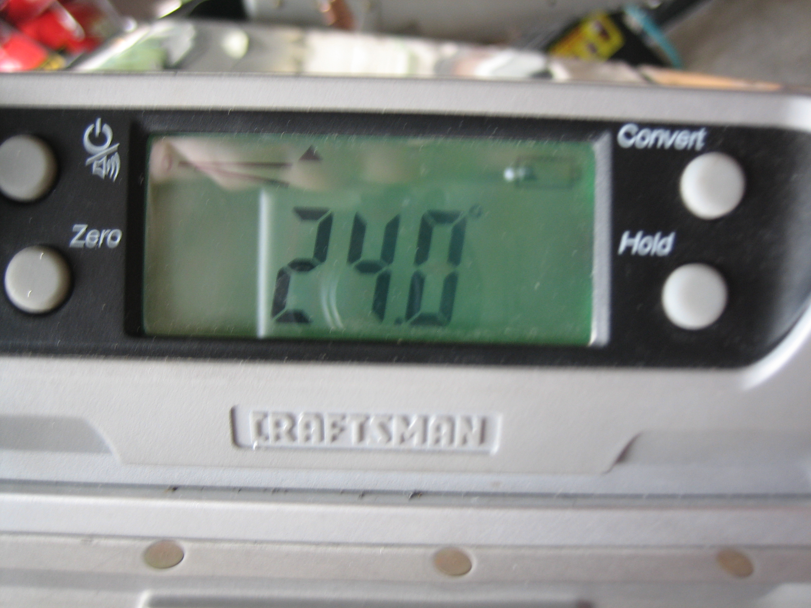
With the adjusted down stop, I can reach 24º deflection from neutral (20º-25º is the specified range).  Since I plan on doing quite a bit of acro, I wanted to get near the upper limit.

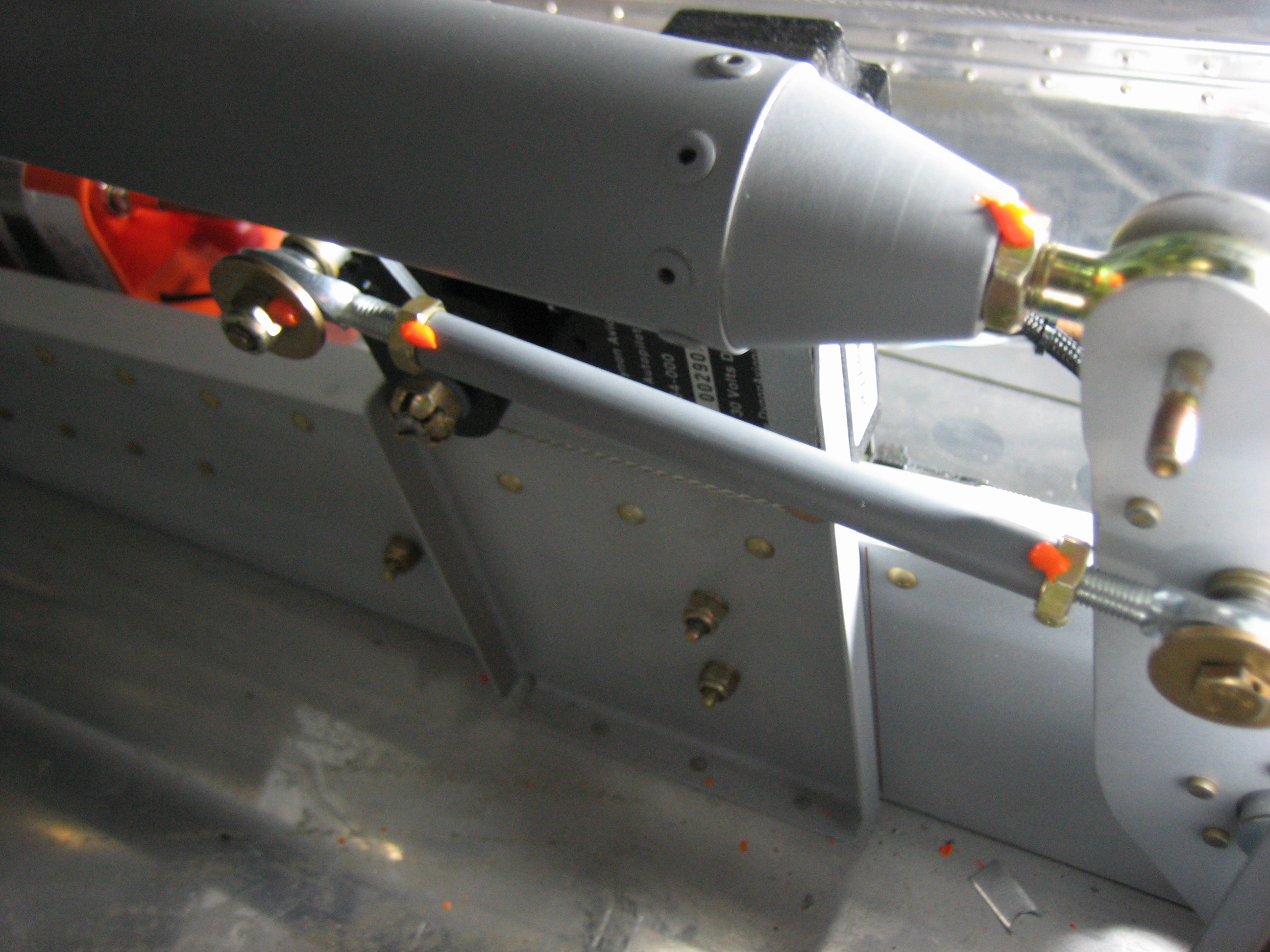
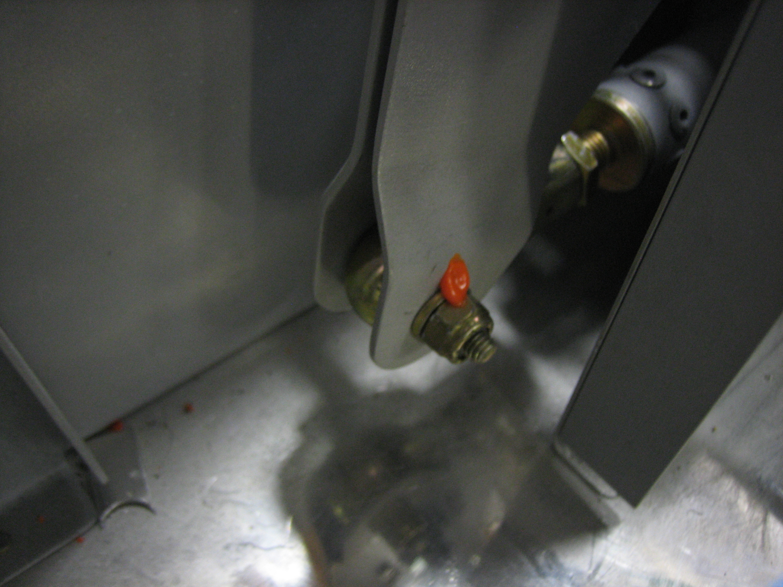
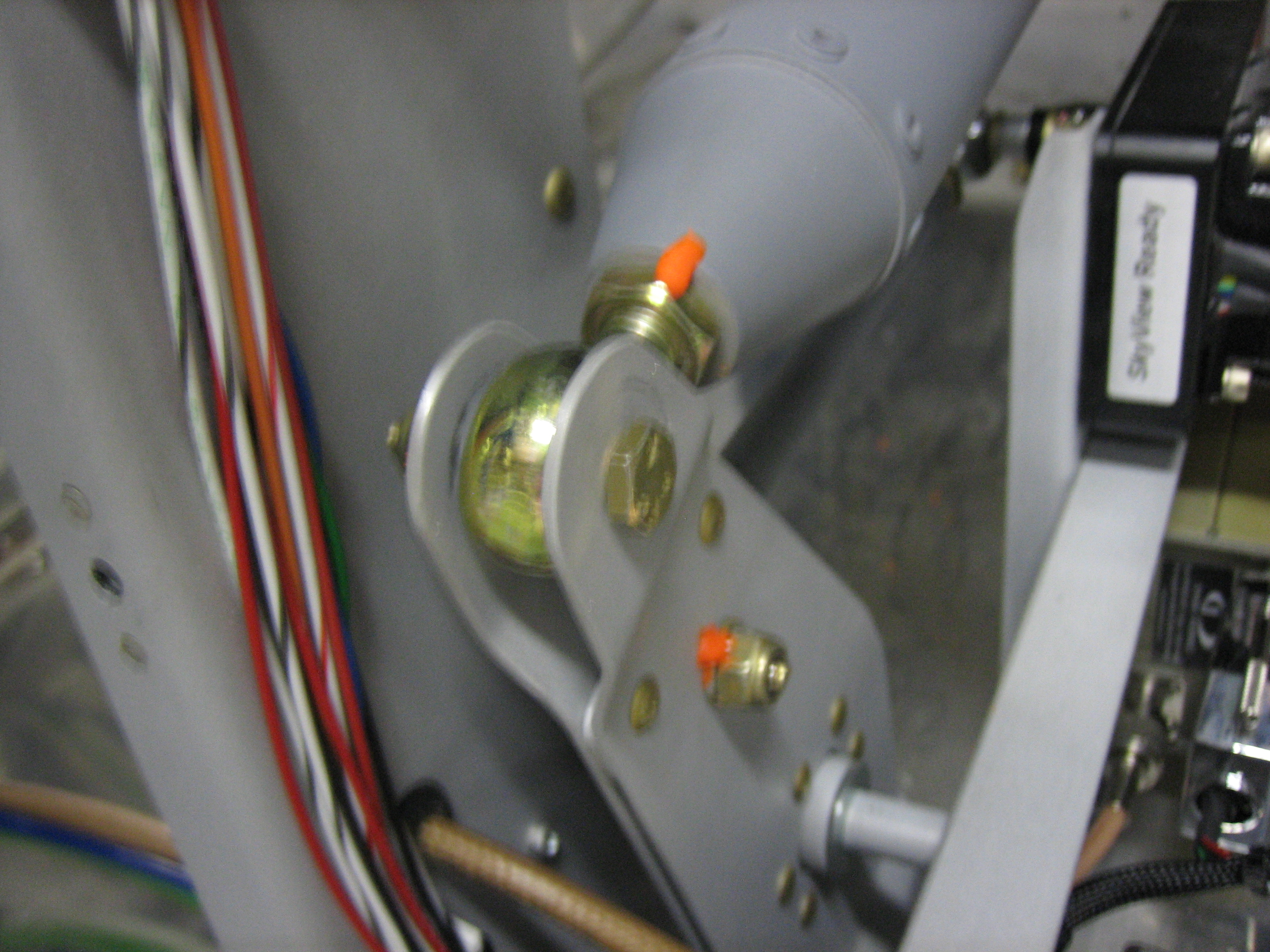
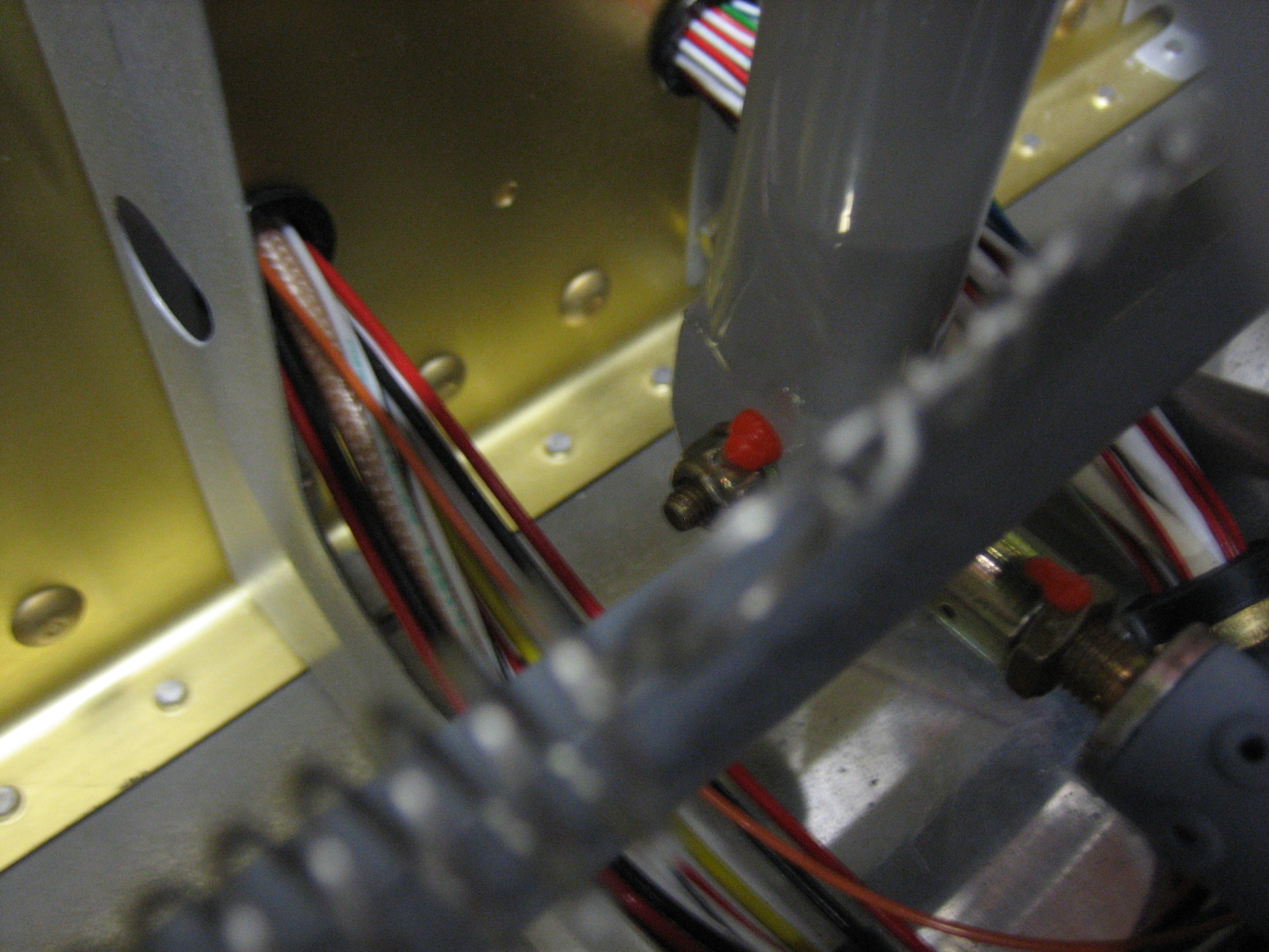
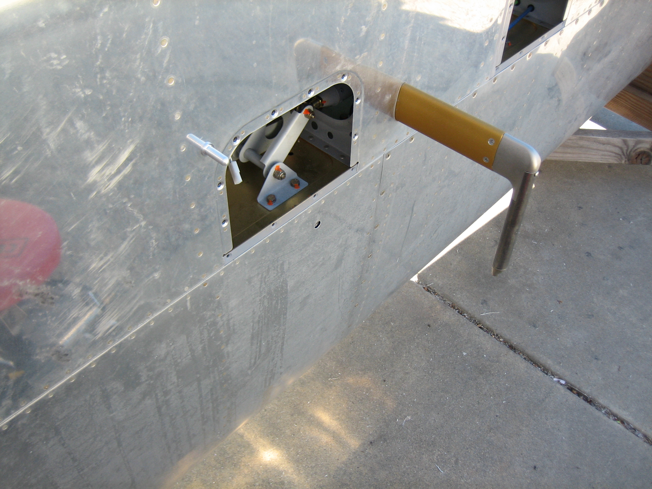
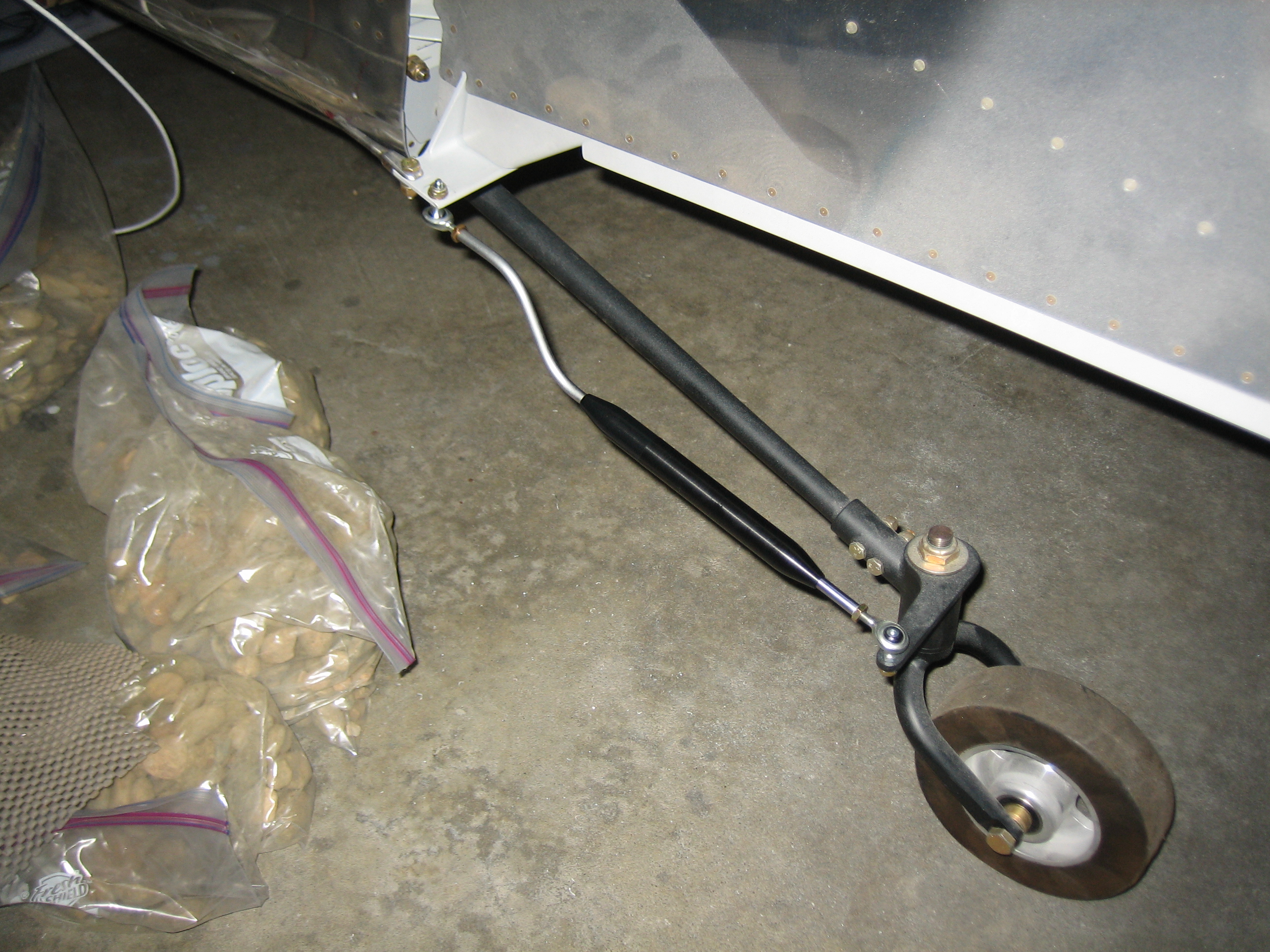
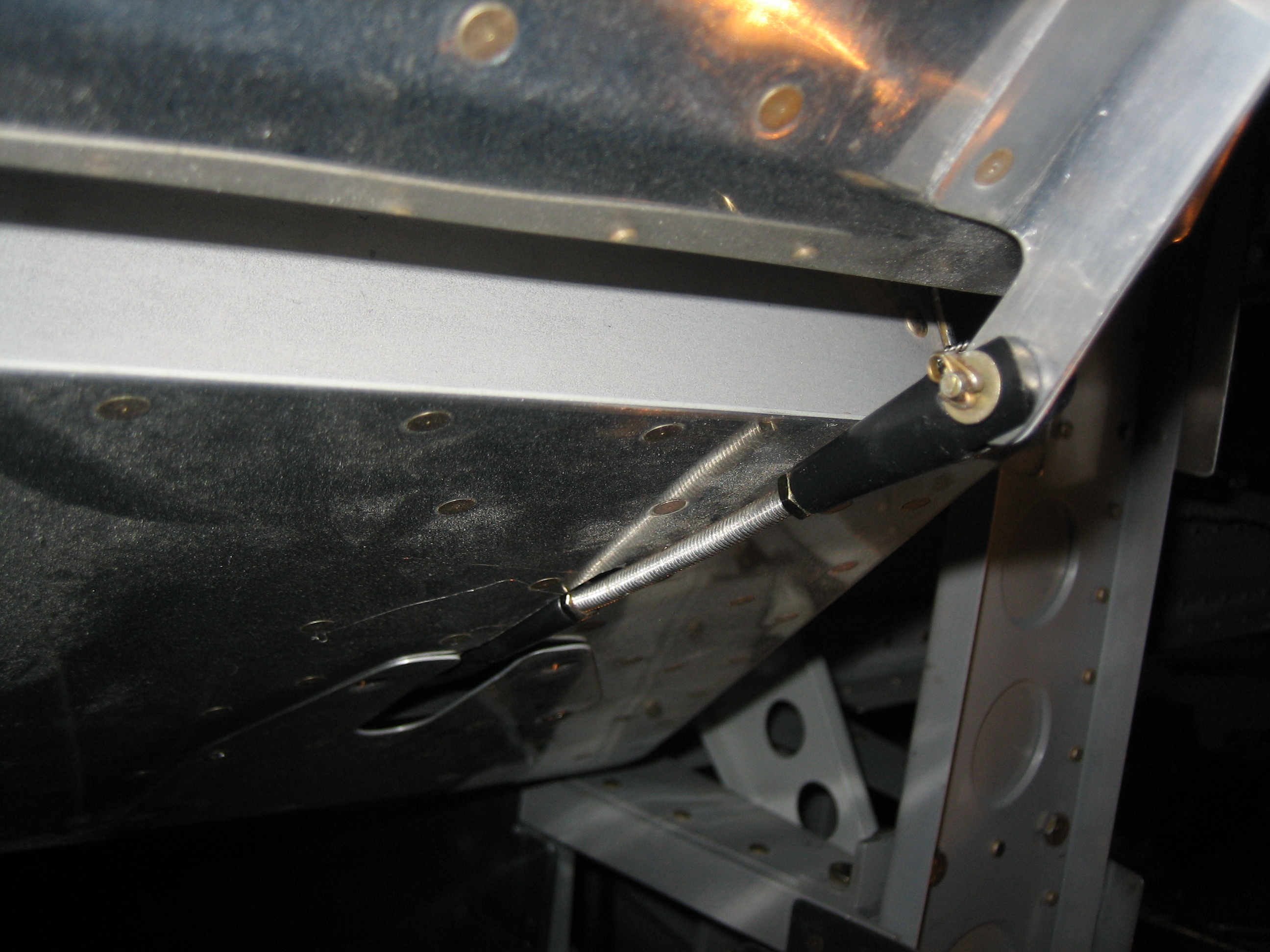
Afterward, I adjusted all of the elevator pushrods to length and torqued the jam nuts.

I had to lengthen the servo pushrod from 6″ to 6 3/16″ center to center to put it at 90º to the servo arm when the elevators are neutral.  I also took the opportunity to prime the servo pushrod and torque everything down.  I still have the forward elevator pushrod to do and the final bellcrank connections to install/torque.

Finished Elevator Pushrods and Worked on Vertical Stabilizer

I finished up the forward elevator pushrod and installed it for good.  Putting the washers between the bellcrank arms and the bearing was a real pain in the ass and required using a washer wrench and looking in a mirror to see what I was doing.  I just noticed that I forgot to add torque seal to the jam nut on the rod end bearing.

I also installed the forward end of the aft elevator pushrod for good.  This didn’t need washers since it uses a larger bearing.

Installing the forward end of the forward elevator pushrod was also a real pain because the aileron interconnect pushrod really gets in the way.  This also needed washers between the forks of the arm, but at least I didn’t have to use a mirror to see what I was doing.

I finished drilling the vertical stabilizer forward spar to the attach bracket and deburred it.

I also epoxied a washer to the forward side of the vertical stabilizer rear spar on the left side since the vertical stabilizer is twisted to the left slightly to counteract the left turning tendency of the airplane.  I also countersunk and installed an AN426 washer in the center hole here since I had to drill out the AN470 rivet I installed there.

When I drilled the bottom of the vertical stabilizer to the tailwheel mount bracket and aft bulkhead, it left some tiny metal shavings between the two pieces.  Fortunately, I had this chip chaser which did a great job of cleaning these out so that the two pieces lay flat against each other.

This is not an airplane part, but the attach point on my inspection mirror finally broke.  I mixed up some epoxy and flox and glued it back together.  This is probably far stronger now than it was originally.

OAT Probe and Empennage Fairings

I drilled the bottom of the wing for the outside air temperature probe.  I installed it in the wing, adjacent to one of the inspection plates (just to the upper left in this picture).

I also cut a small hole in the conduit here so that the OAT probe wires could exit.  You can see the 2 conductor molex connector I used here as well.  I’m honestly not sure the connector is worth the trouble since it would have to be cut off to remove the probe anyway.  It’s probably better to just use a couple of butt splices to crimp the probe wires together with a service loop for future maintenance.  With this done, I think I’m done with the wings until they go to the airport.

I needed a little more filler on the front of the rudder.

…as well as the aft side of the vertical stabilizer.

After that cured, I filed and sanded it down to create a uniform 0.150″ gap (the same as the lower gap under the rudder horn).

I also trimmed a little more off the bottom rudder fairing and then removed all of the gel coat around the hole in preparation for bonding a patch.  For a non-structural patch like this, removing the gel coat isn’t necessary.  I did it more so that the patch would be flush with the gel coat and I wouldn’t have to use as much filler to fair it in.

Finally, I added a patch made of three layers of 8.9oz/yd cloth.

To keep it tight against the fairing, I laid a piece of plastic over the patch and taped it tight.  I then taped a piece of scrap aluminum over the patch to ensure it cures totally flat.

Worked on Nav/Strobe Lights

My Nav/Strobe Lights arrived from Aircraft Spruce today.  I used the adaptor plate and gasket and installed them to the landing/taxi light housing.  I hooked them up to the plane to verify everything works properly.  Holy shit these things are bright.  You can’t be looking anywhere near these things when the strobes go off; it is blinding.

Next up, I drilled the rudder bottom fairing and installed a couple of 4-40 nylock nuts.

I anchored the nuts using a couple of screws and some safety wire.

I then mixed up some 5 minute epoxy with flox and covered the nuts to anchor them inside the fairing.  After the flox cured, I removed the screws and temporarily installed the tail light to ensure the nuts were secure.

Finally, I took one of the lights and installed a waterproof molex connector so that all of the connections can be made at once when installing the wingtip.  I was only able to do this on one of the lights before running out of steam.

Miscellaneous Work on Empennage

I drilled a hole in the aft spar of the left elevator so I could use a loop of safety wire to secure the trim tab hinge pin.

The hinge pin tucks under the spar flange to prevent it from lifting.

From the top, you can see how little of the hinge pin is visible.

I left a small amount of the pin visible at the other end of the hinge so that it’s easy to confirm the hinge is fully inserted during pre-flight.

I pulled the plane out of the garage so that I could rearrange it to work on the empennage.  First up, I riveted and bolted on the up elevator stop.

I then riveted on the plate that ties the vertical stabilizer’s forward spar to the horizontal stabilizer’s front spar.

After spending most of the day cleaning out the garage, the plane is safely tucked back in.

In this orientation, I can actually completely install the empennage and still get the garage door closed.  I can’t walk around the plane that way though, so I’ll likely leave off the rudder and right elevator most of the time though.

I installed the steering link so that I could adjust the length.

Finally, I decided how I was going to mount the ELT antenna, and drilled a hole in the bulkhead and installed the antenna.  I still need to figure out how I’m going to secure the other end of the antenna so that it doesn’t bounce around inside the tail.

More Empennage Work

I drilled out one of the rivets on the horizontal stabilizer and installed an adel clamp to secure the aft end of the antenna.  I also wrapped a bit of silicone wrap around the antenna where it passes over the forward spar of the horizontal stabilizer so that it can’t touch.

I drilled a hole for the tail strobe wiring.  The material here is so thick that a single snap bushing won’t go all the way through, so I glued a snap bushing in from each side.

I also drilled a hole in the aft deck to bring the ELT antenna wire and trim cable through.

The ELT antenna cable crosses the deck and goes through the existing hole in the forward spar of the horizontal stabilizer.

From there, it crosses back across the deck and connects to the antenna.

The trim cable is zip tied to the rear spar of the horizontal stabilizer and then follows the torque tube out to the left elevator.

It’s also zip tied to the torque tube and then goes through a grommet in the left elevator spar.

I installed some d-sub pins and sockets on the cable and trim motor to make it easy to disconnect the motor if it ever needs repair.  I added some heat shrink to each side so that there will be no electrical contact between the wires.  If the elevator ever needs to be removed, it’s fairly easy to fish the cable out through the hole in the spar.

By doubling the wires back on themselves and zip-tying them together, the d-sub pins can’t pull out of the sockets.  This bundle can easily be tucked along side the trim motor.

Finally, I adjusted the length of the pushrod to give me 25º of down movement (up elevator) and 20º of up movement (down elevator).

Afterward, I started fitting the rudder bottom fairing.  This is going to have to move up a bit more, but it’s been a long day and I’m exhausted.

Initial Fitting of Empennage Fairing

I did the initial fitting of the empennage fairing tonight.  These are from Fairings Etc. and the initial fit right out of the box was quite good (much better than the fairings from Van’s from what I’ve heard).  I first used a heat gun on the leading edge to get it to lay down more smoothly on the fuselage.

These flanges were also different in length by about 1/2″, so I marked and trimmed the right one to match the left.  It’s pretty tough to make this symmetrical since everything is curved, but I’m happy with how it turned out.  I then drilled out one of the rivets on each side and tapped it for a #6 screw.  I may end up installing nutplates here since I’d otherwise have to use thread locking compound to keep these from backing out.

I also drilled one hole on each side at the aft end of the horizontal stabilizer and installed a couple of #6 nutplates.  The fit around the fuselage and horizontal stabilizer is great.  I still need to do a little work to get the fit around the vertical stabilizer as nice, but I think this is going to turn out great.

Additional Fitting of Empennage Fairing

I added a couple more nutplates at the aft end of the empennage fairing.

The lower one is through the fuselage side aft of the vertical stabilizer rear spar.  The screw just barely clears the spar flange and setting these rivets was a little tricky.  I double checked, and this easily clears the rudder in all positions.  The plans specify MS24693C28, but they’re clearly too long for most positions.  I’ll probably replace most of them with MS24693C27 or even MS24693C26.

Finally, I trimmed the aft end of the fairing so that it’s flush with the vertical stabilizer and fuselage.  I may end up having to trim the vertical stabilizer and fuselage a bit for rudder clearance, so this may need to be trimmed further.

Continued Work on Empennage Fairing

I drilled an additional hole on each side of the aft flange so that both the forward and aft ends are secure.  This hole also goes through the cover plates on each side.

I also drilled an additional hole at the forward end of the fairing.  I originally tapped the holes here through the longeron, but that will require thread locking compound to prevent these screws from backing out.  I don’t like having to mess with that, so I drilled out the holes to #27 and installed nutplates here.

I used the longeron bending template to mark some additional curves on the empennage fairing.  These will bring the flanges in closer to the screw holes which will help them lay flatter.

Reshaping and Customizing Fit of Empennage Fairing

I spent a little time with the heat gun to reshape a few spots on the fairing that weren’t sitting tight against the aluminum.

The fairing now fits pretty tight all around.  There’s no more than 1/32″gap all the way around.  Here’s the right side of the vertical stabilizer which was one of the worst fitting spots.

And here’s the fit along the right horizontal stabilizer which was also not great.  It now fits pretty well.

To get the fit perfect, I mixed up some epoxy/flox and applied a bead under all of the edges.  I’ll have a little more filling to do underneath each flange after the epoxy sets up.

There were also some minor gaps along the leading edge of the fairing.  This should fit really nicely after I’m done.