Finished Fuel Flow Sensor Wiring and Secured Wiring Runs

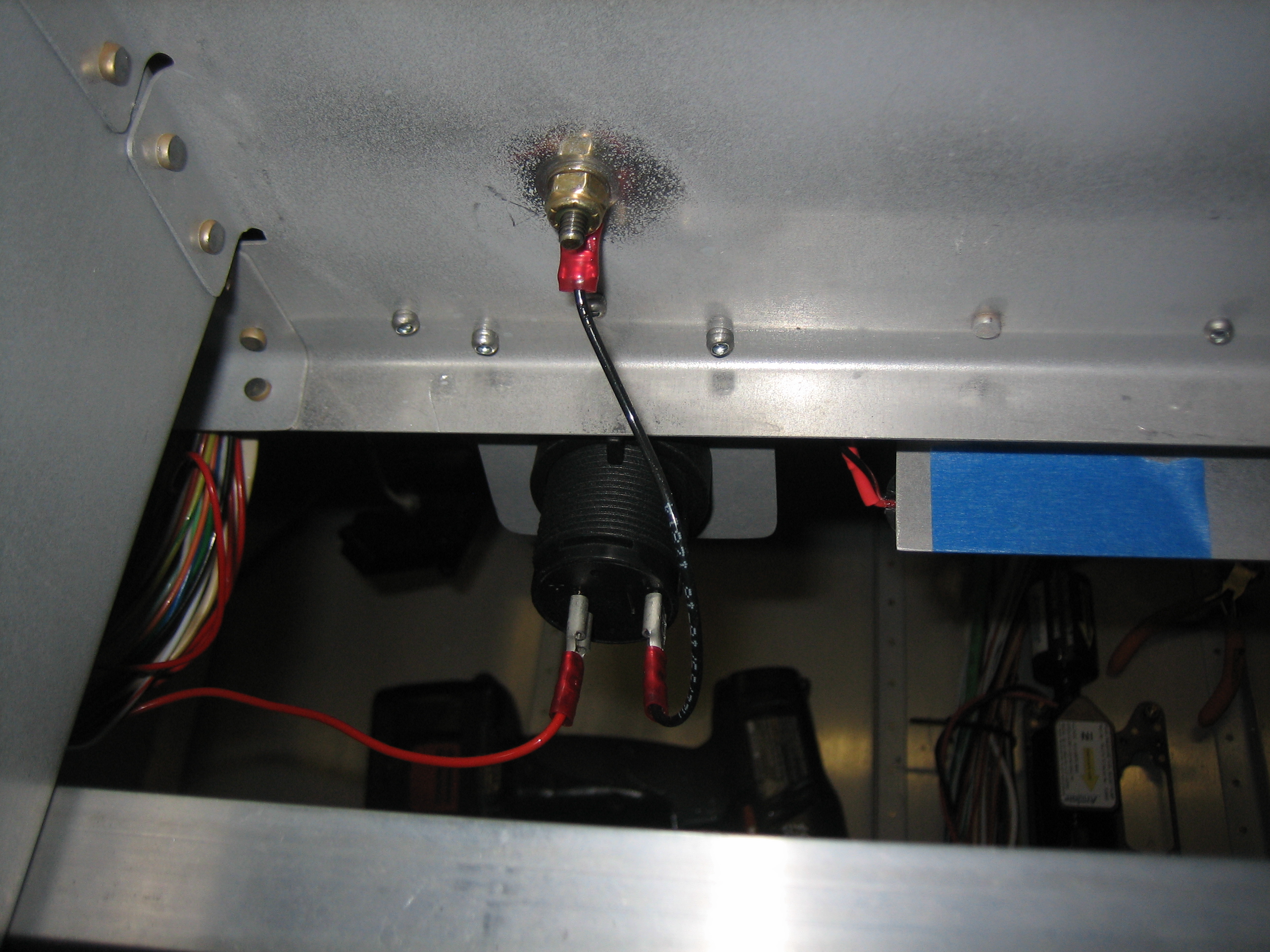
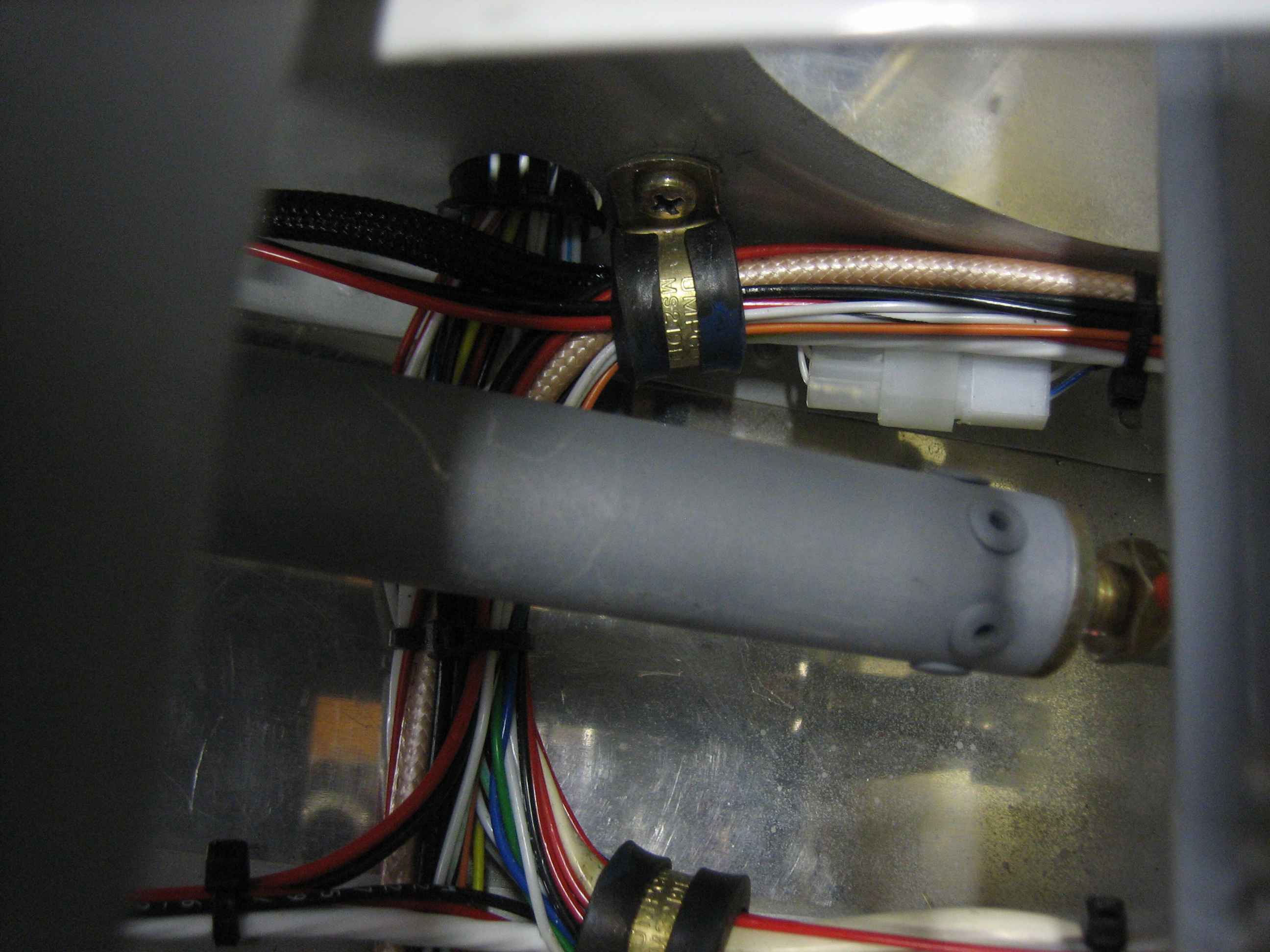
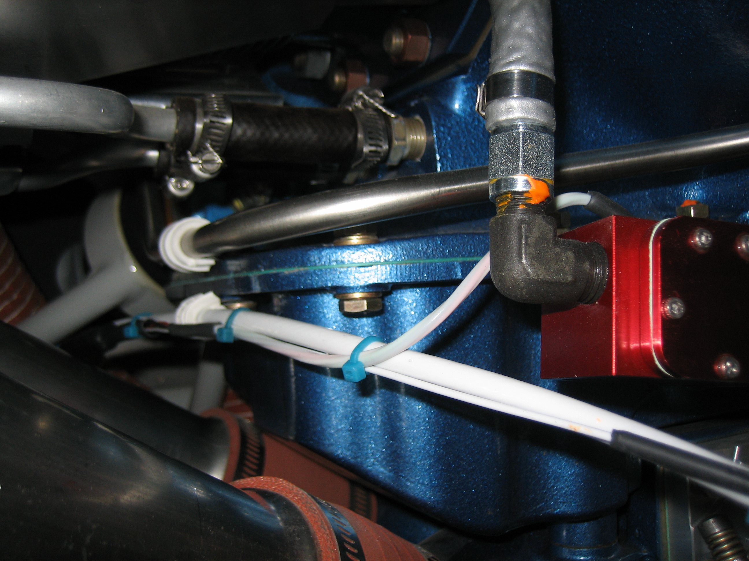
I finished up the fuel flow sensor wiring run by crimping knife connectors on the wires from the EMS and attaching them to the wires from the FT-60 (red cube).  I covered each of the knife connectors and the whole bundle of connectors with some heat shrink tubing and secured the wires with some Tefzel zip-ties.

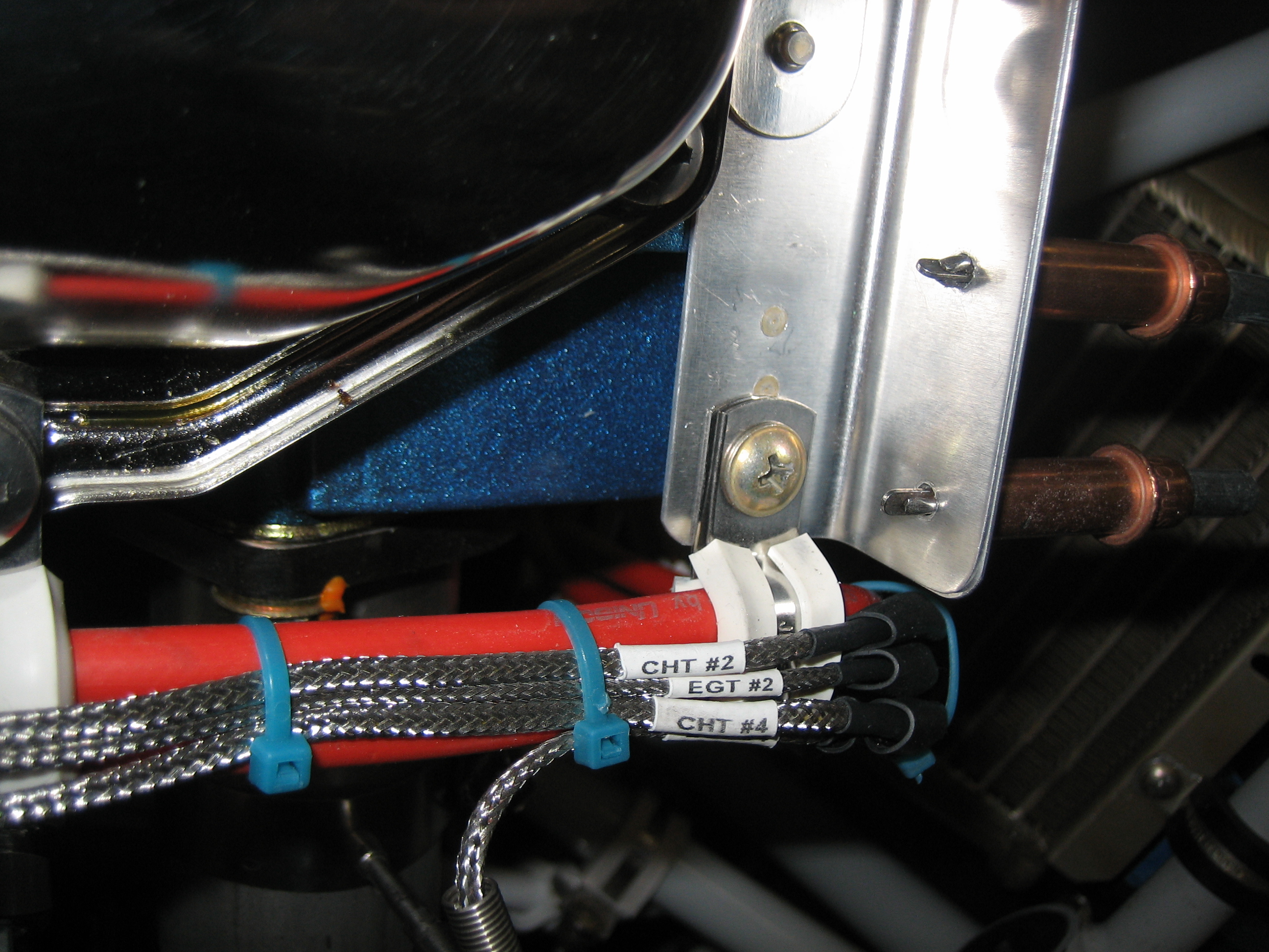
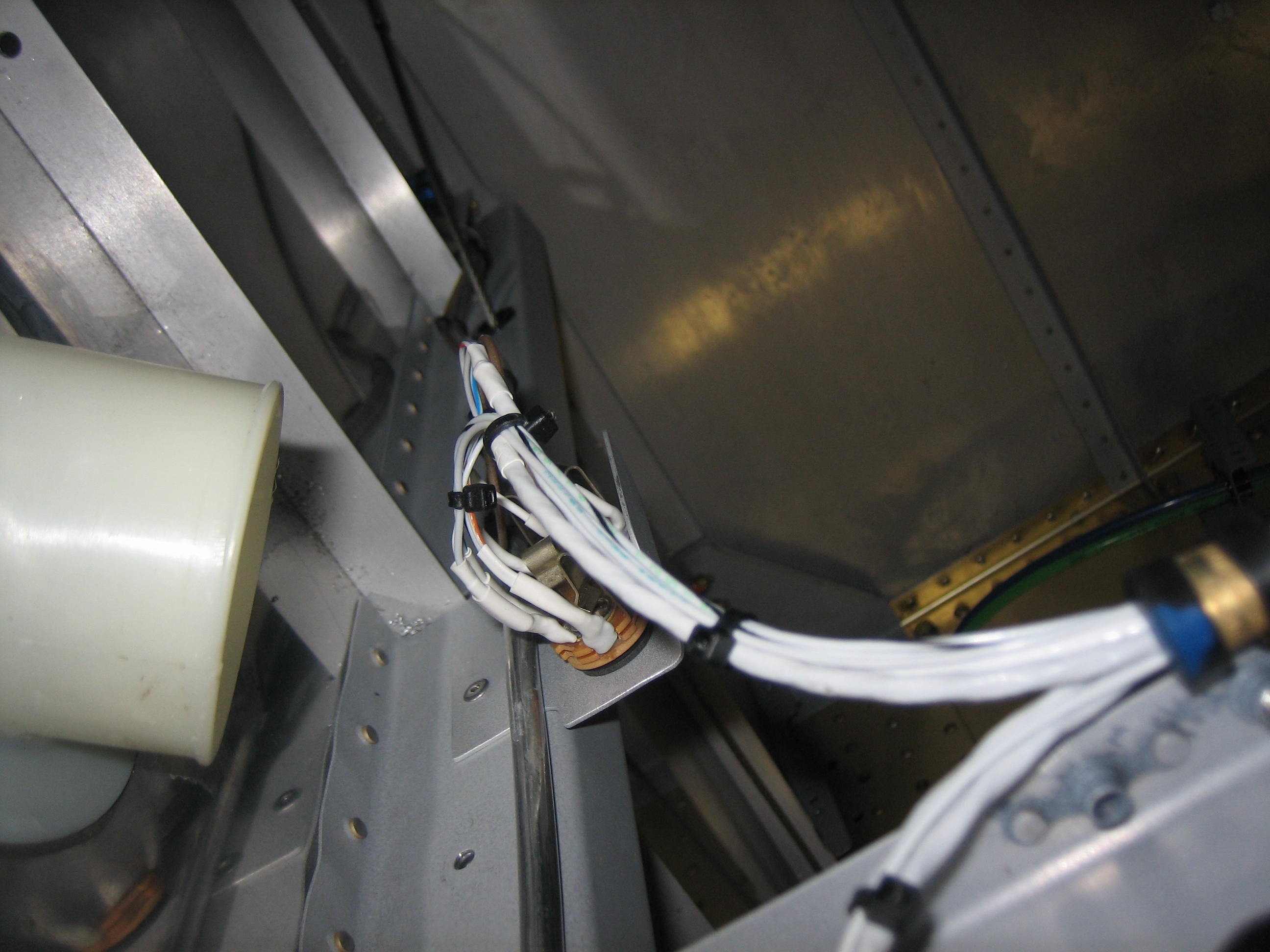
The bundle of ignition, EGT and CHT wires running aft from the #4 cylinder weren’t well supported.  I riveted a K2000-3 nutplate to the side baffle and used a two-wire adel clamp to secure the bundle to the baffles.  This prevents these wires from flexing down and contacting the #4 exhaust pipe (or flexing up and contacting the baffles under negative G conditions).  Other than hooking up the starter wire just before first engine start and the coax wires to the electronic ignition coils, I believe all of the firewall forward wiring is complete.  Other than final hookups of wing and empennage components (lights, roll servo, OAT probe, etc.), I believe all of the firewall aft wiring is complete as well.

Started Disassembling Cabin Area

I removed the canopy frame and started taking out the avionics.  I still need to trim and install the ribs that tie the instrument panel to the subpanel, so I spent a little time determining how to do that.  I also tidied up the wiring harness on the right side.  After the panel comes out, it won’t go back in until the cabin area is painted and the panel is painted and labeled.

Cut Holes for SkyView USB Jacks

I cut the holes in the panel for the SkyView USB jacks.  These are cut just above the screens near the inboard edges, inline with the annunciator lights and controls.

In order to make the opening slightly oversized for paint and to ensure the socket was centered in the hole, I wrapped a couple of layers of electrical tape around the USB plug.


I then filed the hole until the USB jack fit snugly.

I then pushed the plug into the jack and drilled for the mounting screws.  The result was jacks that were perfectly centered in the holes.

Those are the final two holes in the panel.  Afterward, I removed everything from the panel in preparation for painting and labeling.  It won’t go back in too soon because I have a bunch of other things to take care of in the cabin first.  Oh, and you can just see the ribs that I installed between forward and aft radio stack support angles; they’ll help stabilize the panel.

Reinstalled Subpanel and Radio Stack

I reinstalled the center subpanel and Jenn helped me quickly knock out the rivets that tie it to the outer subpanel sections and forward ribs.  I then installed the canopy pivot blocks and radio stack.  You can also see that I added some blue tape on the canopy decks to protect the paint.

Riveted Firewall Flanges and Wrapping Up Wiring

I used the bucking bar I modified to finish riveting the firewall flanges.  The bottom one on each side was still a little tricky, but I managed to get solid rivets in every hole.

I ended up having to move the cigarette lighter plug from just below the forward canopy deck to just below the right edge of the center subpanel.  The old location interfered with the heater valve control cable.

I installed a couple of adel clamps above the VP-X to anchor the main wiring bundle that crosses over the top.

I also buttoned up the pilot’s side headset jack wiring.  You can also see that the capacitive fuel sender wire follows the vent tube down to the exit hole.

Here’s the backside of the cigarette lighter jack.  I grounded the jack locally to the subpanel.

I also wrapped up all of the wiring beneath the seats.  The hardest bit was getting the final adel clamp installed between the forward elevator pushrod.  After that, I installed a few more zip-ties to keep everything tight.  The wiring under the seats is completely done now.

Prepped Instrument Panel for Paint

I’m working seven days a week now, but I took a break in the evening to work on the plane a bit.

My pneumatic squeezer’s adjustable set holder snapped at the base of the threaded section.  I’m going to call Isham and see if I can get this replaced as this shouldn’t have happened.

I drilled and countersunk the holes for the TruTrak Gemini PFD.  I’m still waiting on this from TruTrak, but I’m hoping it will ship soon.

I also countersunk all of the reinforcement angle rivet holes.  You can also see at the bottom of the picture that I countersunk the panel attach holes.

I also countersunk the holes that will attach the hobbs meter and ELT remote.  I’m trying to use all flush head screws across the panel.  I’m still looking for the right screws to attach the USB jacks though.

There were a couple of extra holes in the panel that were intended to attach the crappy Van’s plastic air vents.  I filled them with AN426AD5-4 rivets.

Finally, I prepped and riveted the reinforcement angle to the top of the panel.

The reinforcement angle needed a few relief cuts to clear some of the components that are near the edges.  This relief cut is to clear the alternate static port switch.

These relief cuts are to clear the ears on the annunciator lights bracket.

Finally, this notch is to clear the ELT remote.

Primed Instrument Panel

Sorry for the blurry picture, but I primed the instrument panel tonight.  I applied a little filler last night and first had to sand it smooth.

I filled all of the rivets that attach the reinforcement angle.

I also filled the filler rivets I pull in.  Here are the ones on the sides that would normally be used to attach the air vents.

This is one of the two rivets that fill the holes below the SkyView screens.  These are normally used to attach the panel to the forward ribs.

After cleaning the panel, I primed the back and front.  I put the primer on fairly heavy on the front so that I can sand it a bit before shooting the top coat.  I’d like to make that as smooth as possible.

Painted Instrument Panel

After sanding the instrument panel with 400 grit sandpaper to smooth out a few rough spots, I shot it with the same paint that matches my leather.  I *think* I’m going to have to sand this a bit and shoot another top coat, but we’ll see tomorrow.  You can see in the lower right of the picture that I also painted all of the screws that will be visible on the panel.