Annunciator Control Circuit (Version 2)

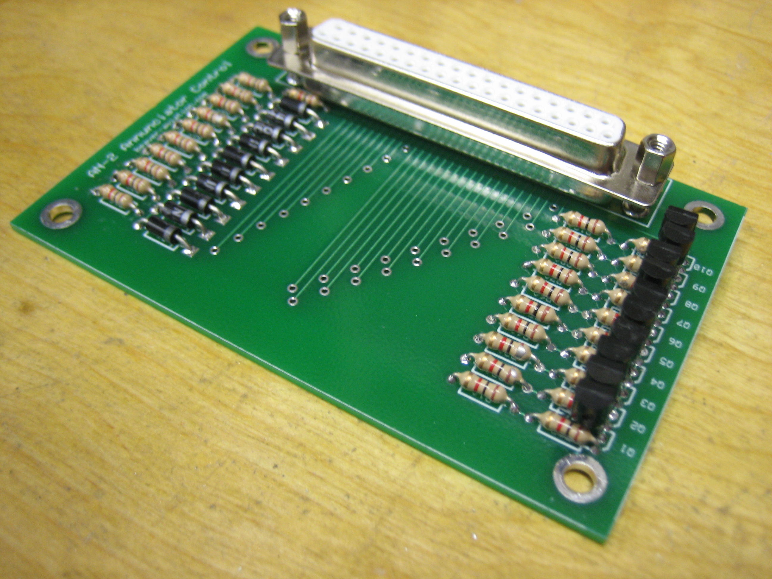
I mentioned a few weeks ago that there was a flaw in my annunciator control circuit.  I redesigned it to provide a pull down resistor for the transistor base and a pull up resistor for the transistor collector.  I received the circuits yesterday and quickly assembled one, but it was not working as expected.  It was late, so I put it off until tonight.

I got started tonight trying to diagnose the misbehaving circuit.  The first three annunciator lights were working as expected, but all of the others (both some high and some low triggers) were misbehaving.  I measured the voltages at various points in the circuit, but they really didn’t make sense.  It was almost as if I had installed PNP transistors instead of NPN transistors.  I checked the bag from Radio Shack and they were indeed NPN.  I breadboarded a single light control circuit and still couldn’t get it to work properly.  At this point, I was beginning to wonder if I had completely forgotten my circuit design skills from university.  I was disassembling the breadboard circuit and noticed that the transistor was smoking hot.  This shouldn’t have happened because the transistor should either be fully off or fully saturated.  In either case, the power dissipated in the transistor should have been essentially zero.

It was really starting to seem like the only explanation was that it was a PNP transistor.  I looked up the part number on the transistor, and sure enough it was a PNP.  I went through the whole bag from Radio Shack and sure enough, every transistor was a PNP despite the bag indicating they were NPN.  I started desoldering the transistors off of the board and noticed the first three (the circuits that worked) were NPNs that I had left over from the first circuit I built.  This really pissed me off.  I wasted hours trying to diagnose a problem caused by Radio Shack’s mislabeled transistors.

Anyway, I replaced all of the incorrect transistors and unsurprisingly, the circuit worked flawlessly.  All of the annunciator lights have nice sharp on/off transitions and work exactly as expected.

Mated the Wings

My brother Seth flew out from KY yesterday to help me mate the wings.  The weather was spotty in the morning, so we got started a little later that I’d have liked.  We pulled the plane out into the driveway and temporarily fit the wings with some hardware store 7/16″ bolts.

Next up, we leveled the fuselage laterally and hung two plumb bobs off of each wings.  I tied a piece of fishing line to the cord on the outer two plumb bobs so that I could easily compare the position of the inner two plumb bob cords to the line to see if the wings had any sweep in them.  I also took some measurements from the tail to make sure each wing had the same amount of sweep.  Finally, I checked the wing incidence on both sides to make sure they were the same.

With the wings straight, I installed the flaps to see how they fit against the fuselage.  The good news is that the height on both sides is perfect and the inboard end of the flap skins just kisses the bottom of the fuselage.  Unfortunately, with the wings perfectly straight, the joint between the flaps and the side of the fuselage wasn’t uniform.  The gap got progressively wider towards the trailing edge of the flap.  I decided to sweep the wings back slightly to make the gap uniform (I probably only brought the wing tips back 1/4″ or so from straight across).  This will make no discernible difference in the flying qualities, but the aesthetics of the flap/fuselage intersection are significantly improved.

After triple checking everything, I laid out some marks to ensure that I had 5/8″ of edge distance (from the center of the bolt) in all pieces, then progressively drilled out the hole to just under the final size.  I then used a 0.3115″ reamer to bring the hole up to final size providing a snug fit for the bolt.  I used a drill cup on the first three sizes to ensure that I was drilling absolutely perpendicular to the material.

My buddy Andre dropped by to check out the progress, and we drilled the bottom wing skin and the wing root fairings for #8 screws and my brother trimmed them to the fuselage.

Next, I installed the flaps and pushrods and cut out the flap pushrod holes.  These are odd shaped holes due to the changing geometry between the flap weldment and the flap as they’re moved up and down.

Heres a rough idea what the hole on the left side looks like.

The side of the fuselage has an arch shaped hole to clear the end of the flap pushrod when the flaps are fully retracted.

The bottom of the fuselage has a slanted and tapering hole to provide clearance for the pushrod and it moves through its range of motion.  I have about 1/8″ all around the pushrod in all positions.

Seth removed the tank attach brackets and bent them so that they’re flush against the side of the plane and flush with the back of the fuel tank attach bracket.  Afterward, I drilled the fuel tank attach bracket for the bolt that ties these together.  Once the wings are back off the plane, I install a nutplate on each bracket to allow these to be screwed together.

I was getting really damn cold.  I was still in shorts and a long sleeve t-shirt, and it had dropped to 46º before I gave up and decided to call it a night.  Hopefully I can rig the ailerons tomorrow morning pretty quickly.

Rigged Ailerons

I got started this morning by adjusting all of the aileron pushrods so that both ailerons are aligned with the flaps when the sticks are perfectly vertical and I had the same number of threads showing on each end of the pushrods.  I then torqued all of the jam nuts down and applied torque seal.

Next, I figured out what will work for the aileron stops.  These are 1/2″ long, 5/8″ diameter spacers with a 3/16″ hole in the middle.  I probably need to shorten them slightly to allow me to insert the appropriate washers to give the bearing some play.

This gives me 30.2º upward deflection (25º-32º is the recommended range).

And 16.5º downward deflection (15º-17º recommended range).

My brother and I pulled the wings off and got them covered and the plane back in the garage just as the rain started.  I wasn’t able to fabricate the fuel lines, but those can happen after the wings are installed for good.

Wired Copilot’s Headset Jacks

I wired the copilot’s headset jacks tonight.  I wired the pilot’s side weeks ago, but for some reason didn’t get around to the copilot’s side until tonight.

On this side, I routed the wires over the duct like I meant to do on the pilot’s side.  I’ll secure these wires a little better later.

More Misc Fuselage Tasks

My wife and I celebrated our 11 year wedding anniversary tonight.  She had to get up early for work tomorrow though, so I came out to the garage for a few minutes tonight to knock a few tasks off the to-do list.  I got started by crawling under the fuselage and deburring/scotchbriting the flap pushrod holes.

After that, I decided to torque and seal a bunch of the fuselage fasteners that are in for good.  First up, I retorqued the center pushrod jam nuts and sealed them.

Next, I torqued and sealed the bolts that secure the center pushrod to the control sticks.

Finally, I torqued and sealed the bolts that attach the tank attach brackets to the fuselage.

Rigged Elevators

I finished drilling the aft deck and longerons to the elevator up stop.

I also finished drilling/reaming the forward vertical stabilizer support bracket to the forward spar of the horizontal stabilizer.

The elevator down stop needed quite a bit of material removed to achieve the recommended amount of deflection.

With the up stop manufactured to plans, I get 31.1º of upward deflection (25º-30º is the specified range).  It looks like a number of builders have ended up with slightly more than the 30º limit.

With the adjusted down stop, I can reach 24º deflection from neutral (20º-25º is the specified range).  Since I plan on doing quite a bit of acro, I wanted to get near the upper limit.

Afterward, I adjusted all of the elevator pushrods to length and torqued the jam nuts.

I had to lengthen the servo pushrod from 6″ to 6 3/16″ center to center to put it at 90º to the servo arm when the elevators are neutral.  I also took the opportunity to prime the servo pushrod and torque everything down.  I still have the forward elevator pushrod to do and the final bellcrank connections to install/torque.

Finished Elevator Pushrods and Worked on Vertical Stabilizer

I finished up the forward elevator pushrod and installed it for good.  Putting the washers between the bellcrank arms and the bearing was a real pain in the ass and required using a washer wrench and looking in a mirror to see what I was doing.  I just noticed that I forgot to add torque seal to the jam nut on the rod end bearing.

I also installed the forward end of the aft elevator pushrod for good.  This didn’t need washers since it uses a larger bearing.

Installing the forward end of the forward elevator pushrod was also a real pain because the aileron interconnect pushrod really gets in the way.  This also needed washers between the forks of the arm, but at least I didn’t have to use a mirror to see what I was doing.

I finished drilling the vertical stabilizer forward spar to the attach bracket and deburred it.

I also epoxied a washer to the forward side of the vertical stabilizer rear spar on the left side since the vertical stabilizer is twisted to the left slightly to counteract the left turning tendency of the airplane.  I also countersunk and installed an AN426 washer in the center hole here since I had to drill out the AN470 rivet I installed there.

When I drilled the bottom of the vertical stabilizer to the tailwheel mount bracket and aft bulkhead, it left some tiny metal shavings between the two pieces.  Fortunately, I had this chip chaser which did a great job of cleaning these out so that the two pieces lay flat against each other.

This is not an airplane part, but the attach point on my inspection mirror finally broke.  I mixed up some epoxy and flox and glued it back together.  This is probably far stronger now than it was originally.

Installed GTN 635 Serial In Lines

I realized a couple of months ago that I needed one of the serial input lines on the GTN connected so that the SkyView could share traffic with it.  The avionics shop mailed me a few extra wires with high-density d-sub pins crimped on, but I’ve avoided installing them because it is such a pain to remove the connectors.  Anyway, I decided to bite the bullet and do that tonight.  It wasn’t too bad.  I had everything back together and the wire harness zip-tied in under an hour.  I went ahead and hooked up three serial in lines in case I ever need to hook anything else up.