Trimmed Aft End of Cowl

I trimmed the sides of the lower cowl and then sanded them so that they tuck in against the hinge (which I also drilled but didn’t get a picture of).  I drilled one hole through the top of each side into the hinge to lock the position of the lower cowl in place.

I then marked and trimmed the aft end of the top cowl.  This will need a little sanding, but it is enough to let it drop down against the hinge.

Unfortunately, there is still a gap along the sides.  The plans (and other builder’s websites) say these should overlap along the sides so that you can trim them both to get a perfectly straight joint.

The left side is even worse with a roughly 1/8″ gap down the entire side.

The fit at the front still looks great.  Here’s the lineup at the top.

And the lower point on the cowl lines up nicely with the spinner.  Clearly the front of the cowl is in the right spot and the back is pulled in as tight as it can go.  Time to chat with Van’s again about this.

Tech Counselor Visit, Elevator Trim Wiring, Exhaust Heat Shields

My tech counselor, Brian Dal Porto, stopped by tonight to check out my progress.  The last time he stopped by was near the end of the wing construction which was about 19 months ago (holy crap, has it really been that long?).  He checked out my fuselage construction, as well as engine installation and wiring.  He said everything looks good and there wasn’t anything I needed to change which is great.

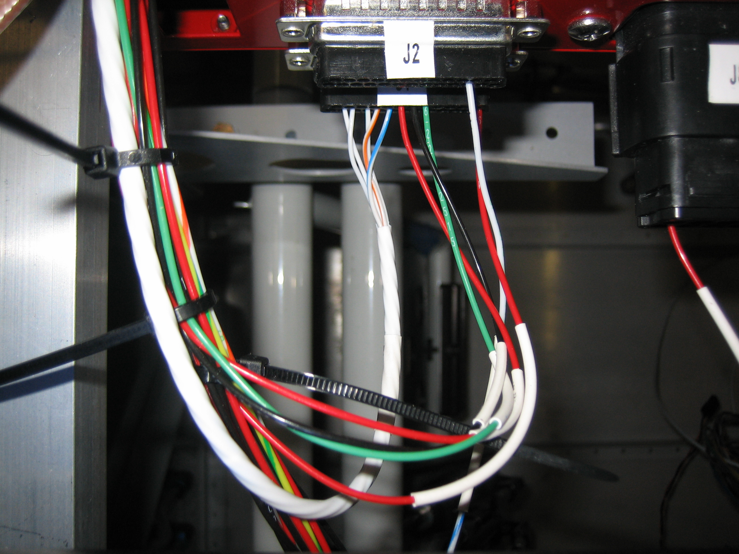
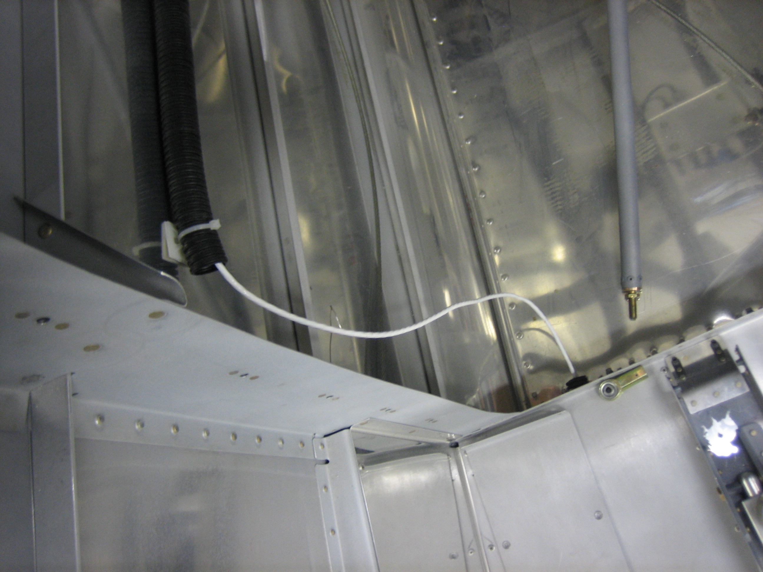
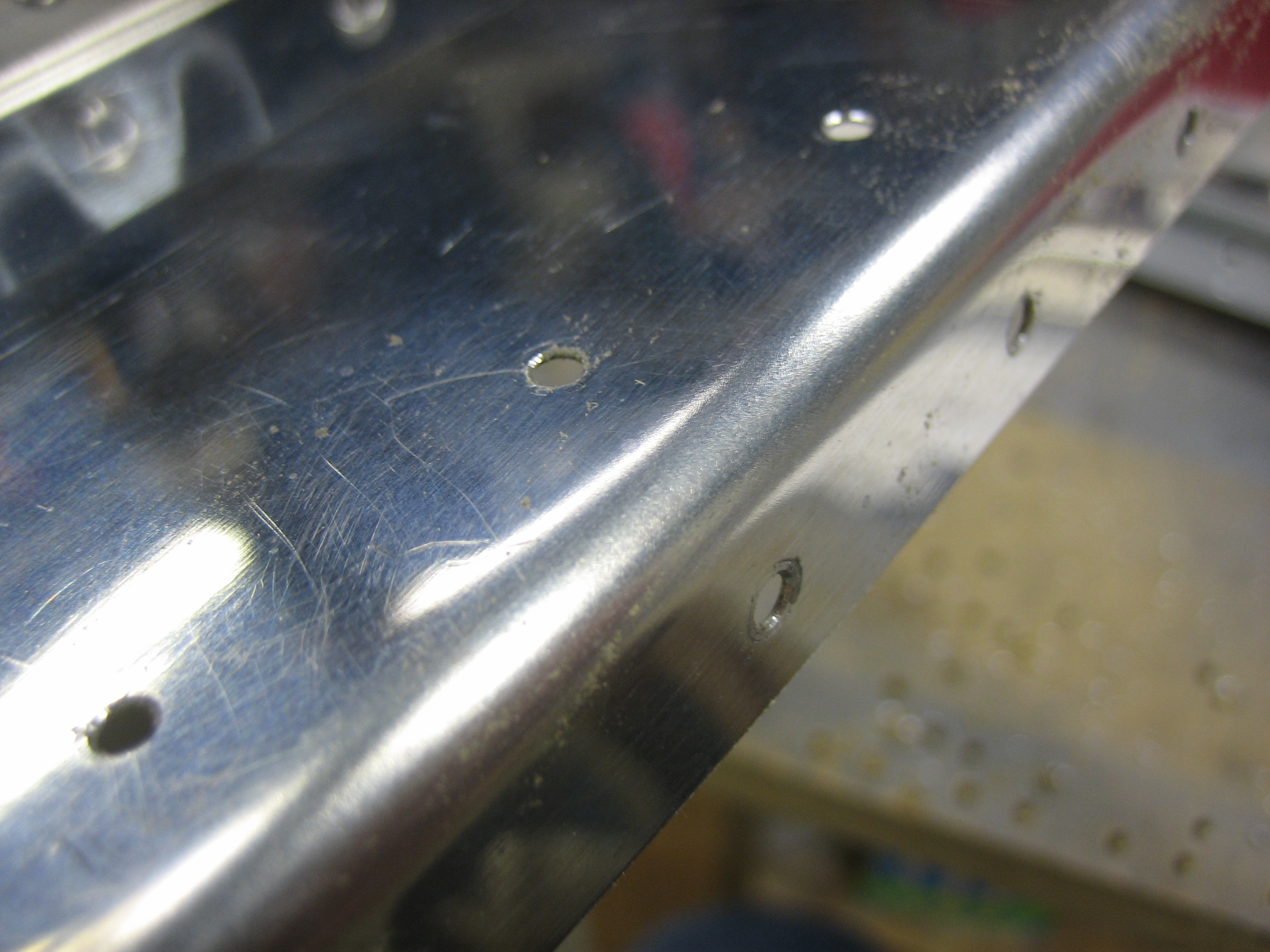
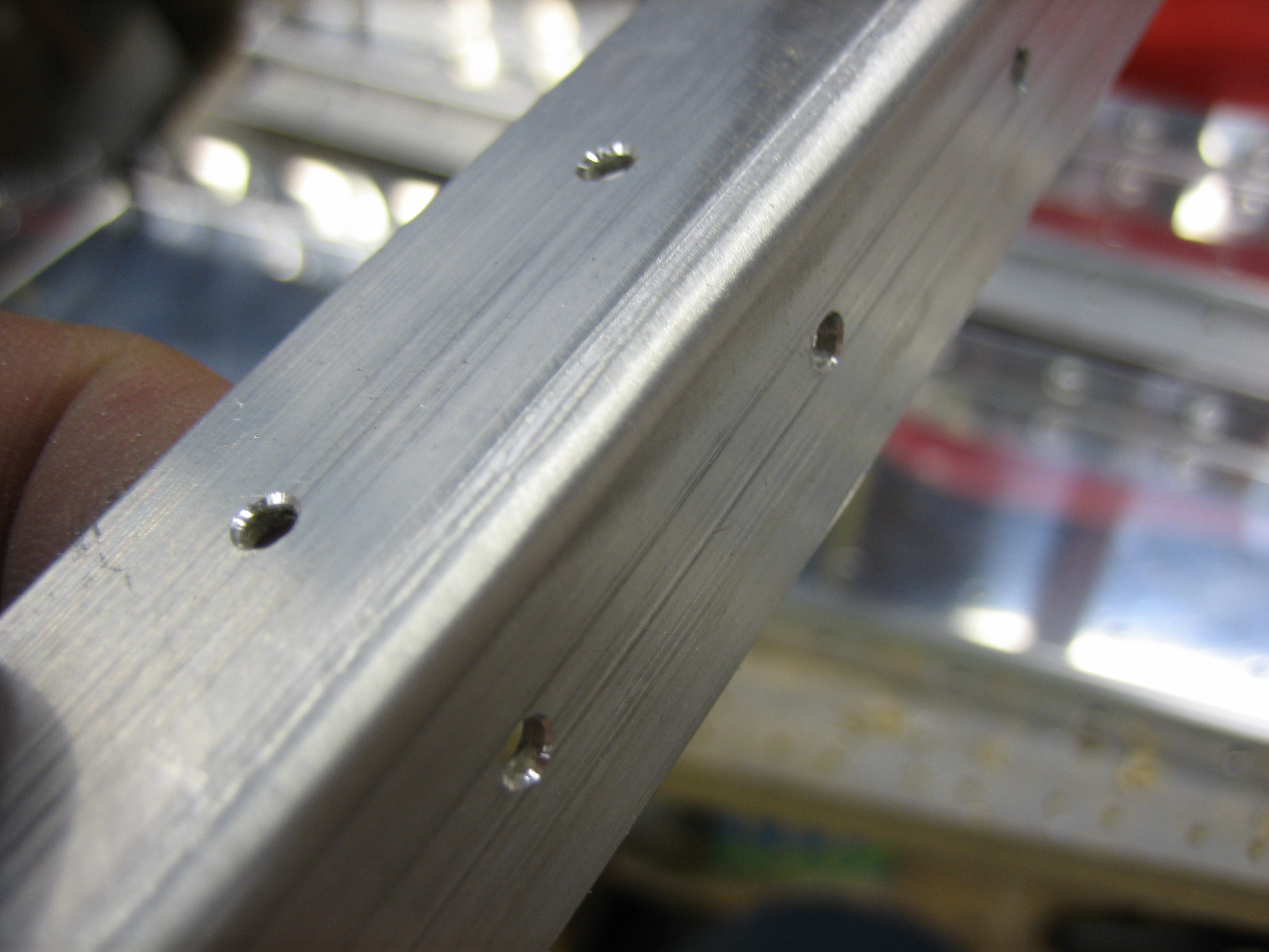
After he left, I took care of a couple of small tasks before heading in to get some work done for my day job.  First up, I ran a cable for the elevator trim.  This is a 5-conductor cable from Ray Allen that is specifically meant for wiring their trim systems.  It contains five 26AWG wires that match the colors of the wires coming out of the trim and position sensor boxes.  I was hoping that one 25′ cable would be enough to do both the aileron and elevator trim wiring, but it was quite a bit short.  I’m going to replace my flap position sensor wires with another piece of this, so another 20′ should be plenty for the aileron trim and flap position.  Here’s the wire where it comes out of the J1 connector on the VP-X (the five small wires that come out of the connector and go into the larger white cable.  You can’t see it, but there is a heat shrink label on the cable.

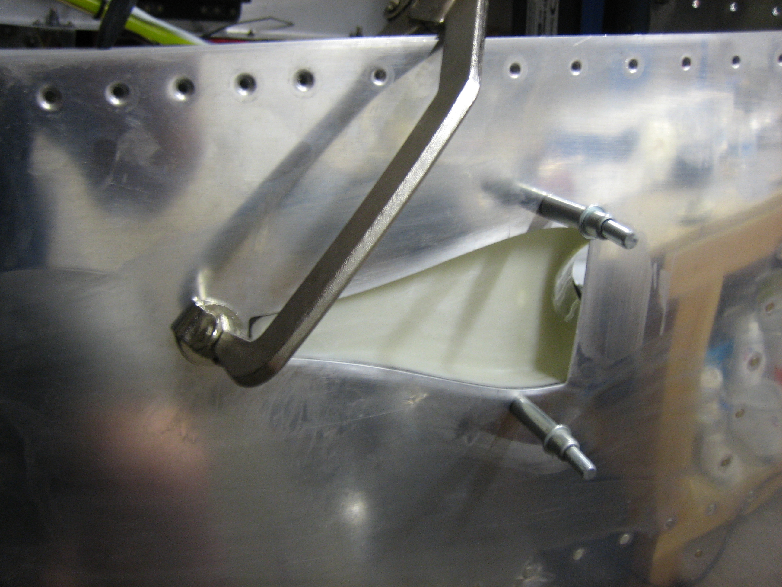
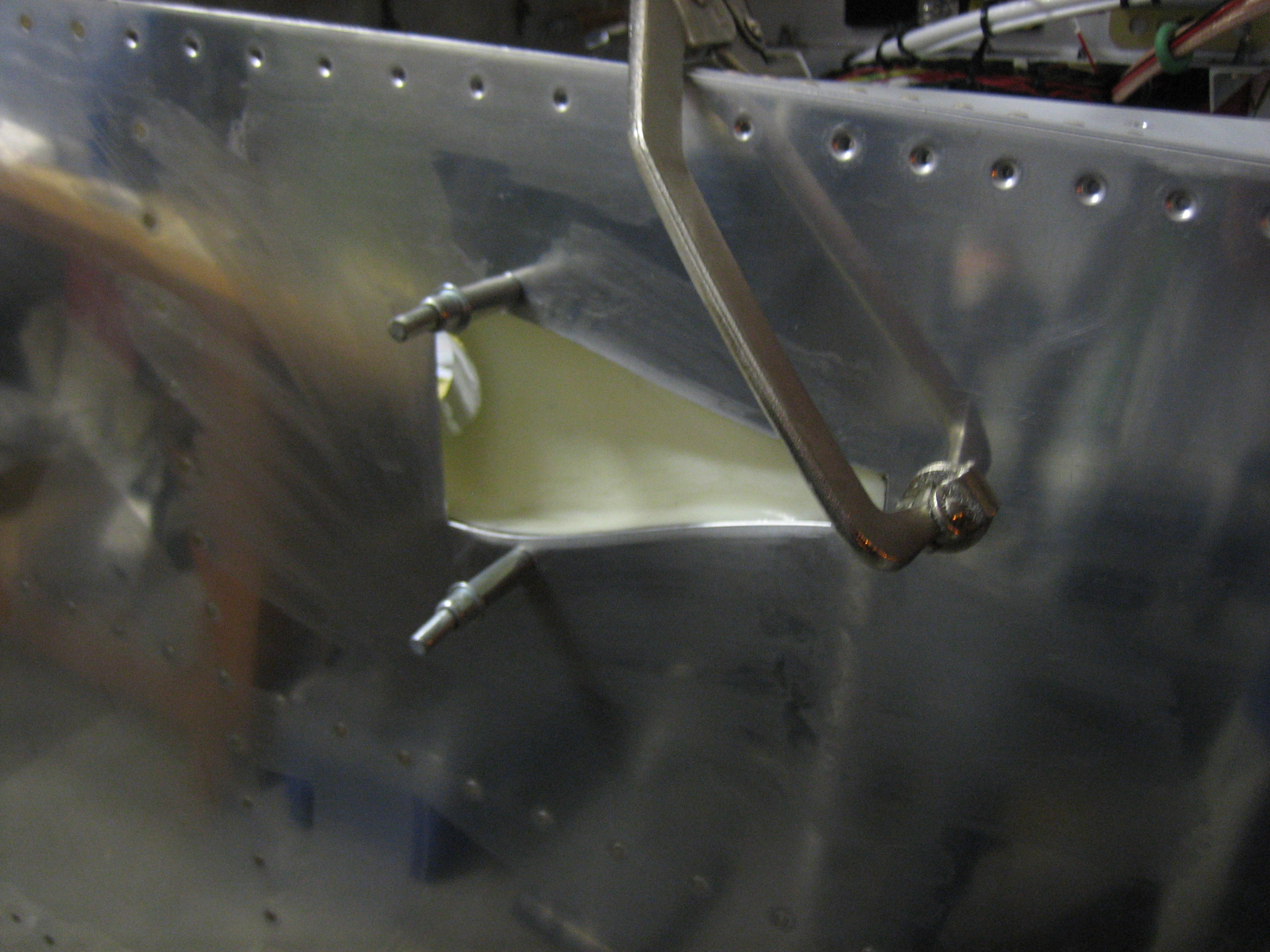
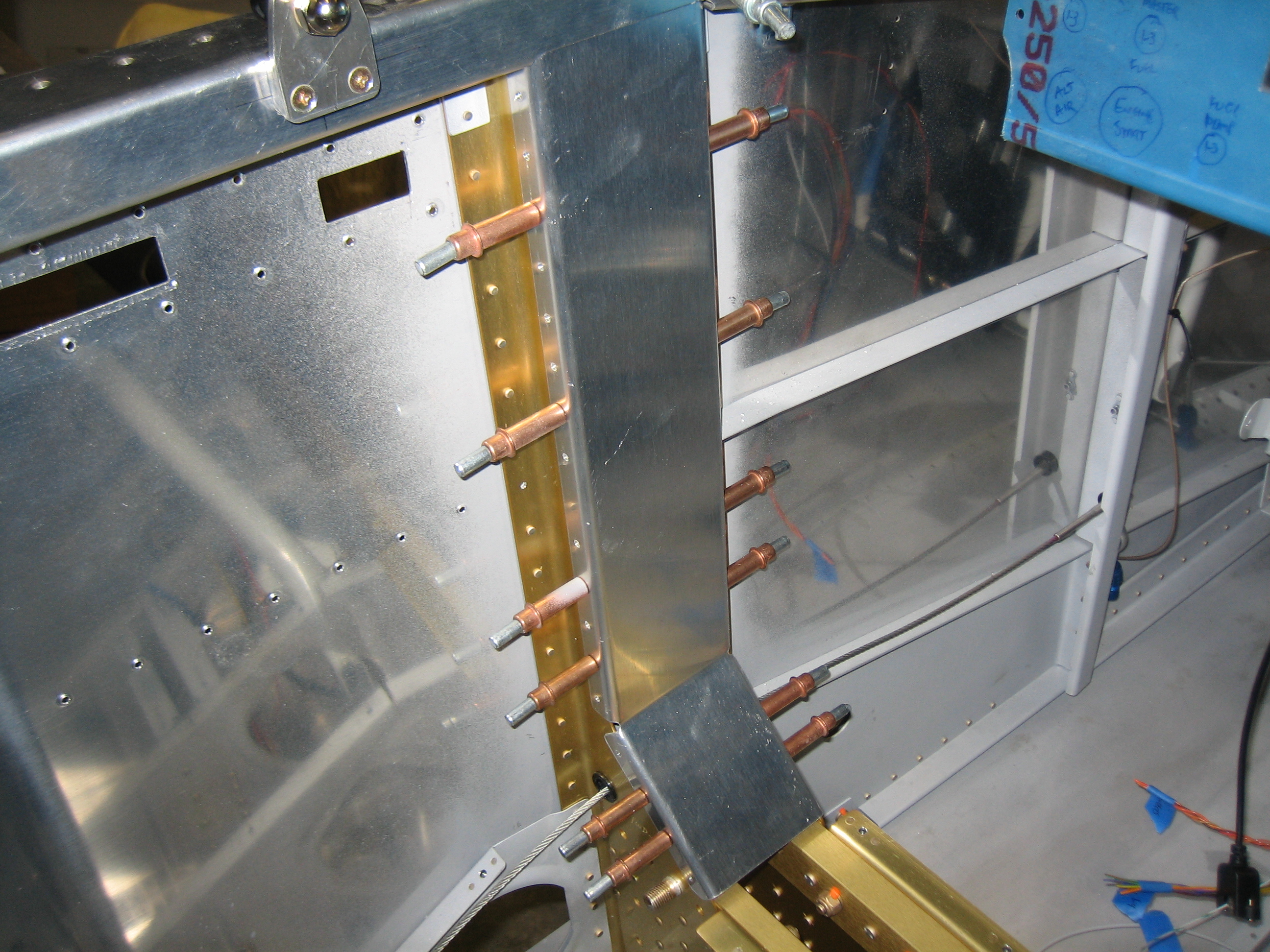
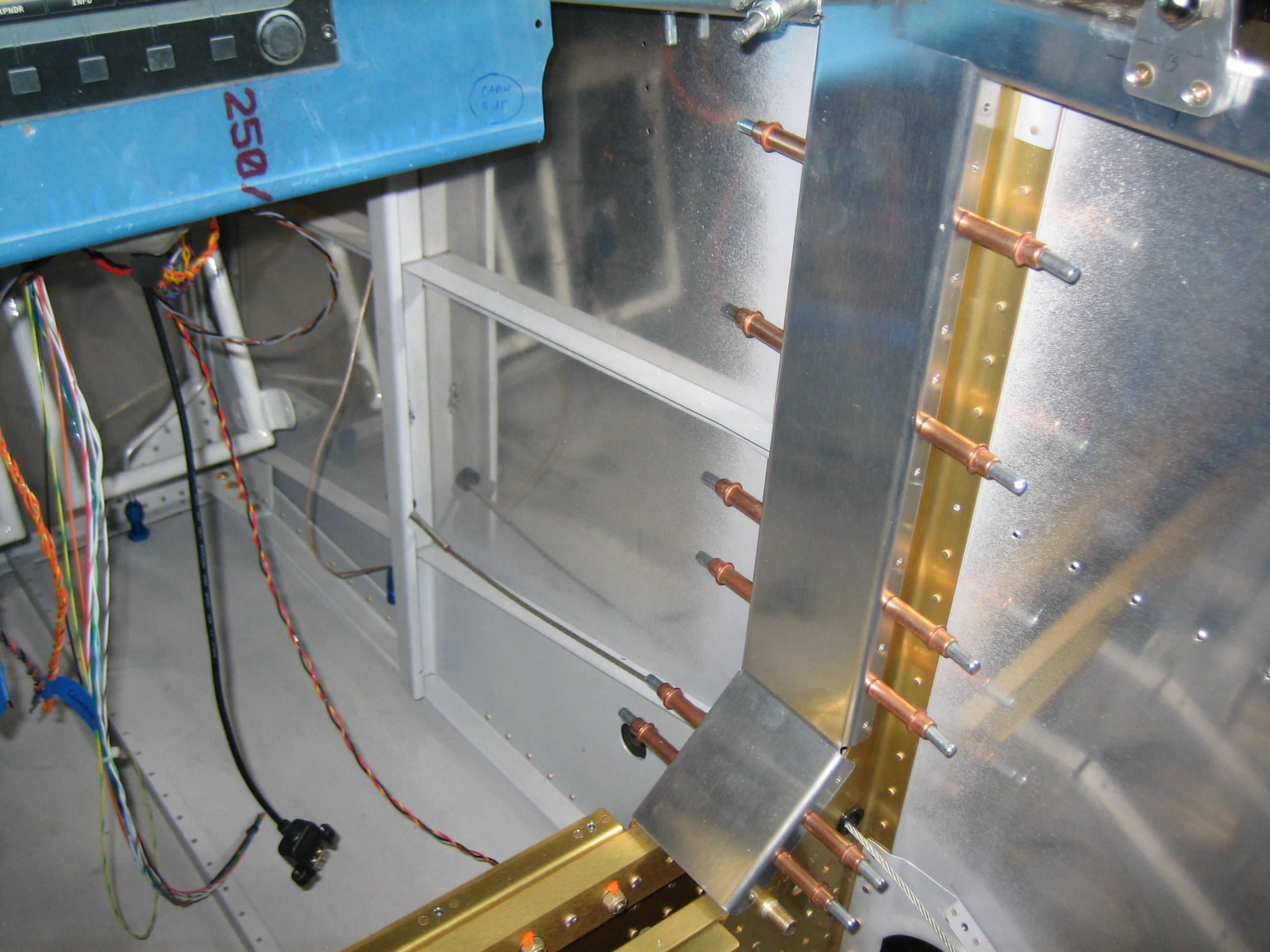
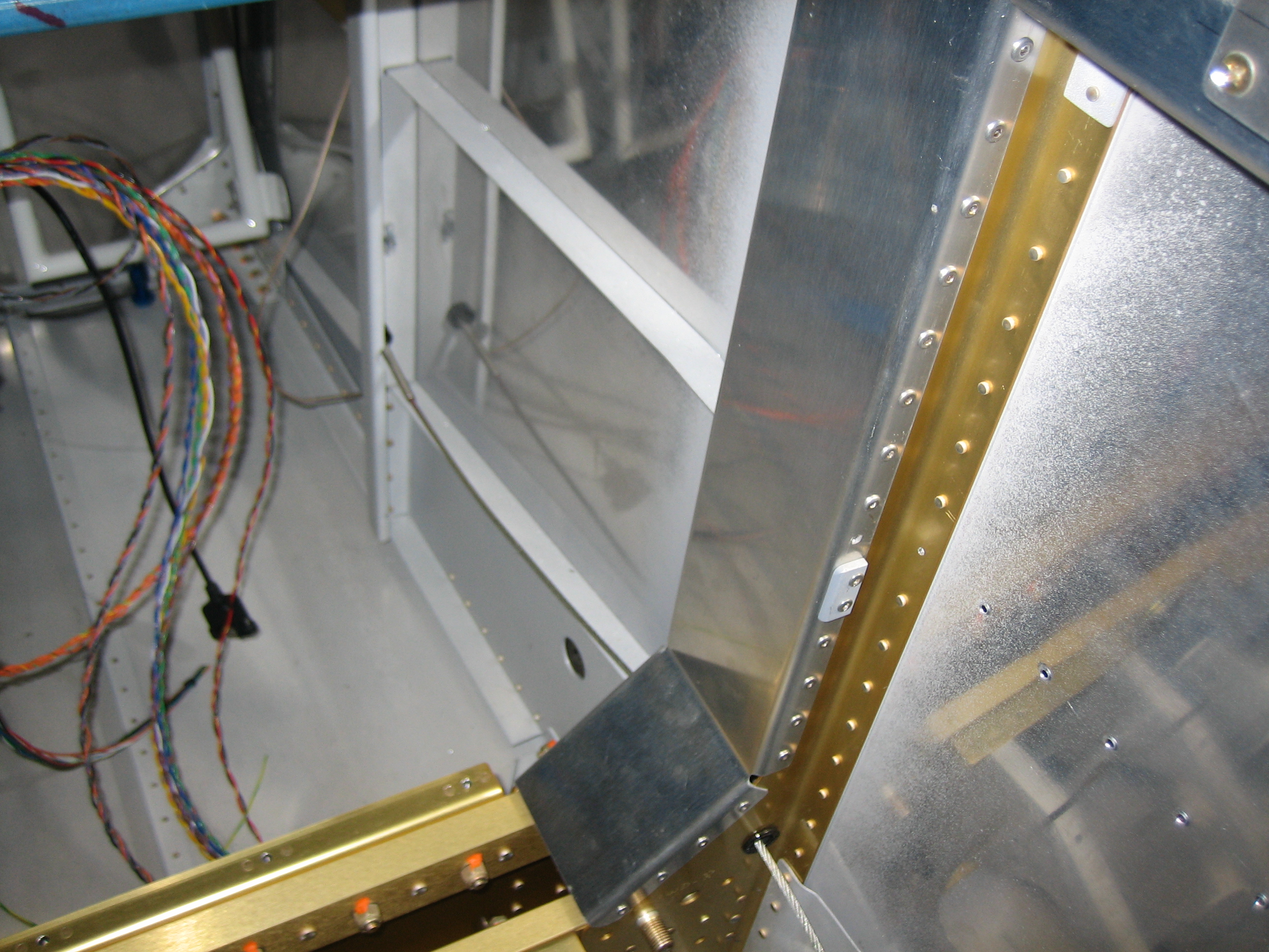
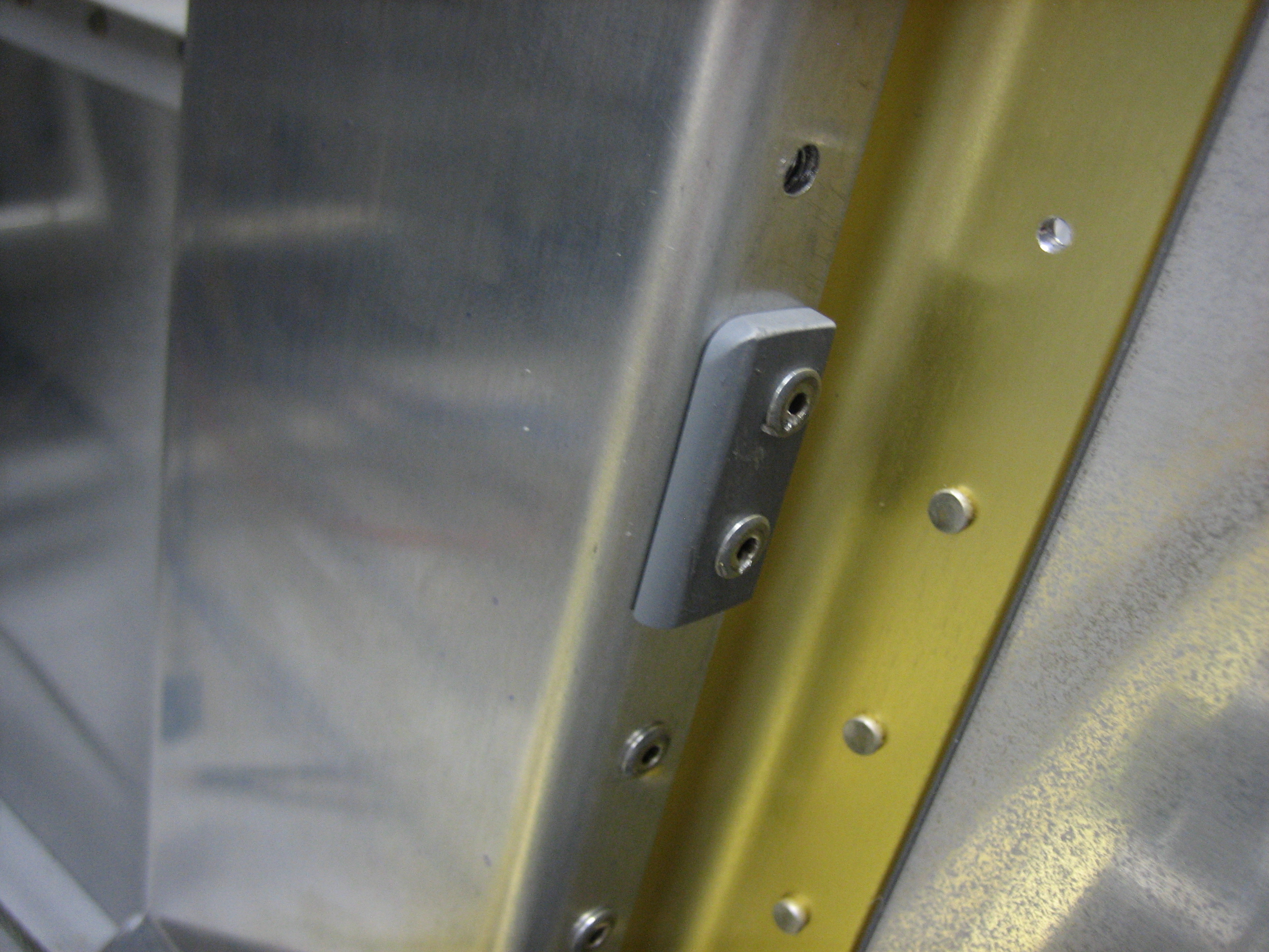
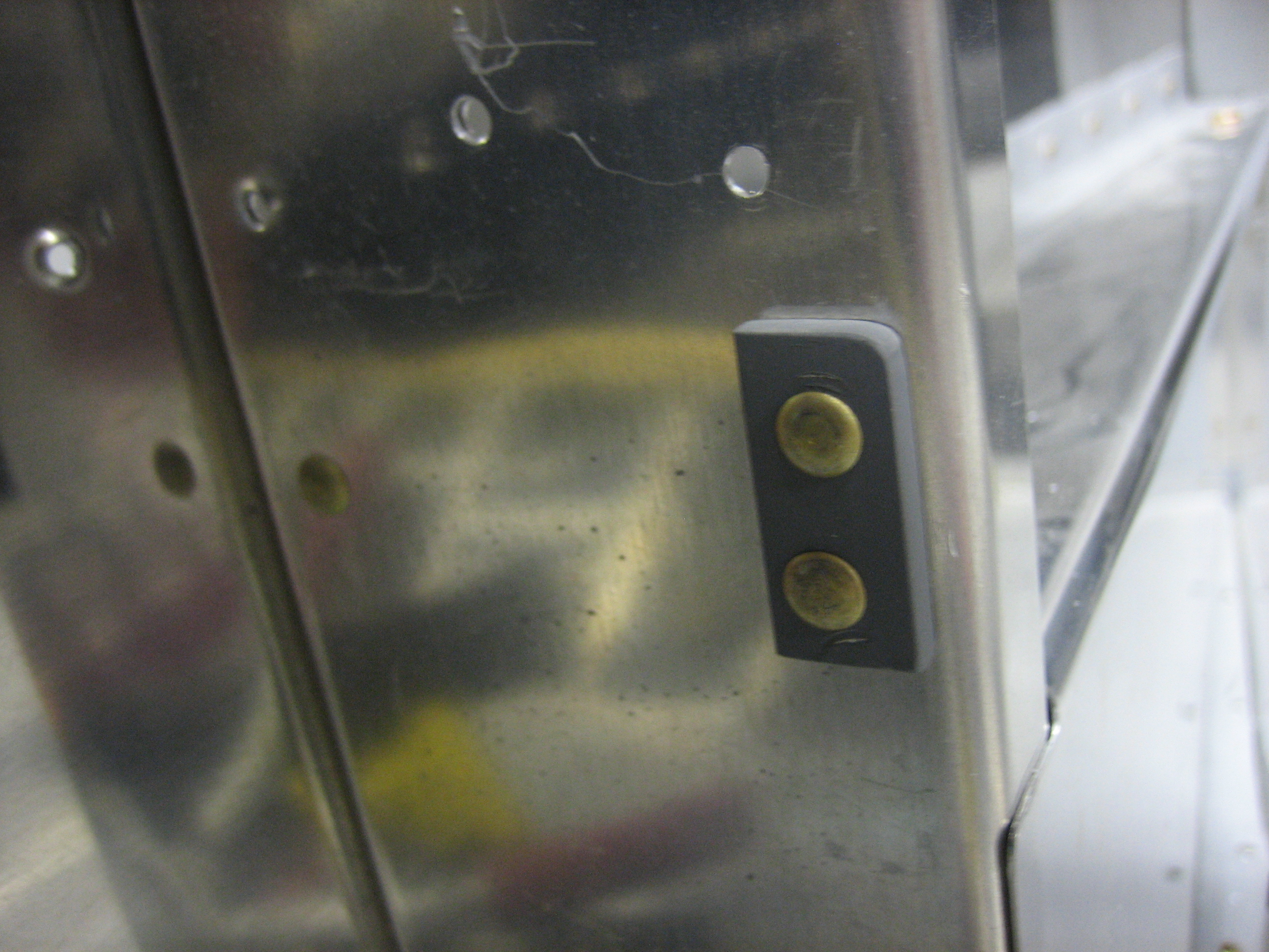
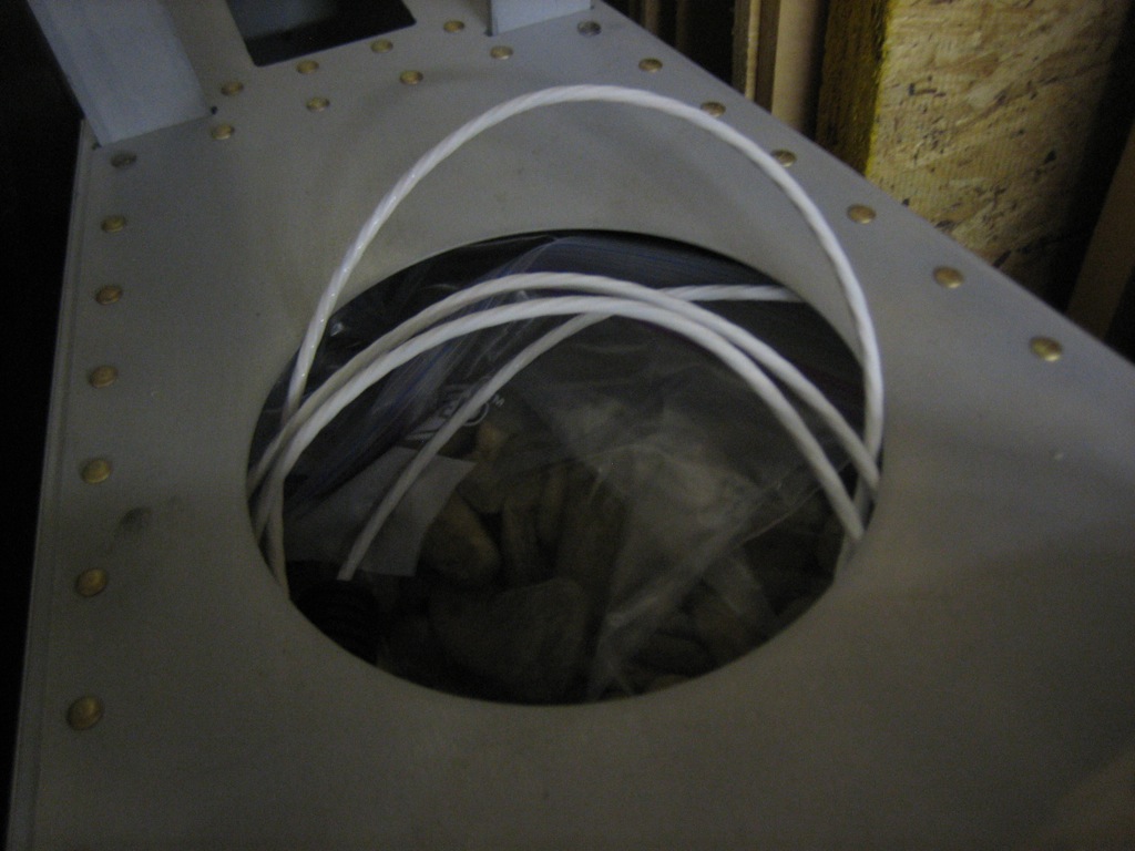
The cable runs down the forward center tunnel and under the copilot’s seat and through the right conduit and comes out here behind the baggage bulkhead.  There will be an adel clamp here securing this to the bulkhead as it runs up to the tail conduit (along with the tail position/strobe wires).

There’s a few extra feet of wire back here.  I’ll cut it to length when I mount the tail.

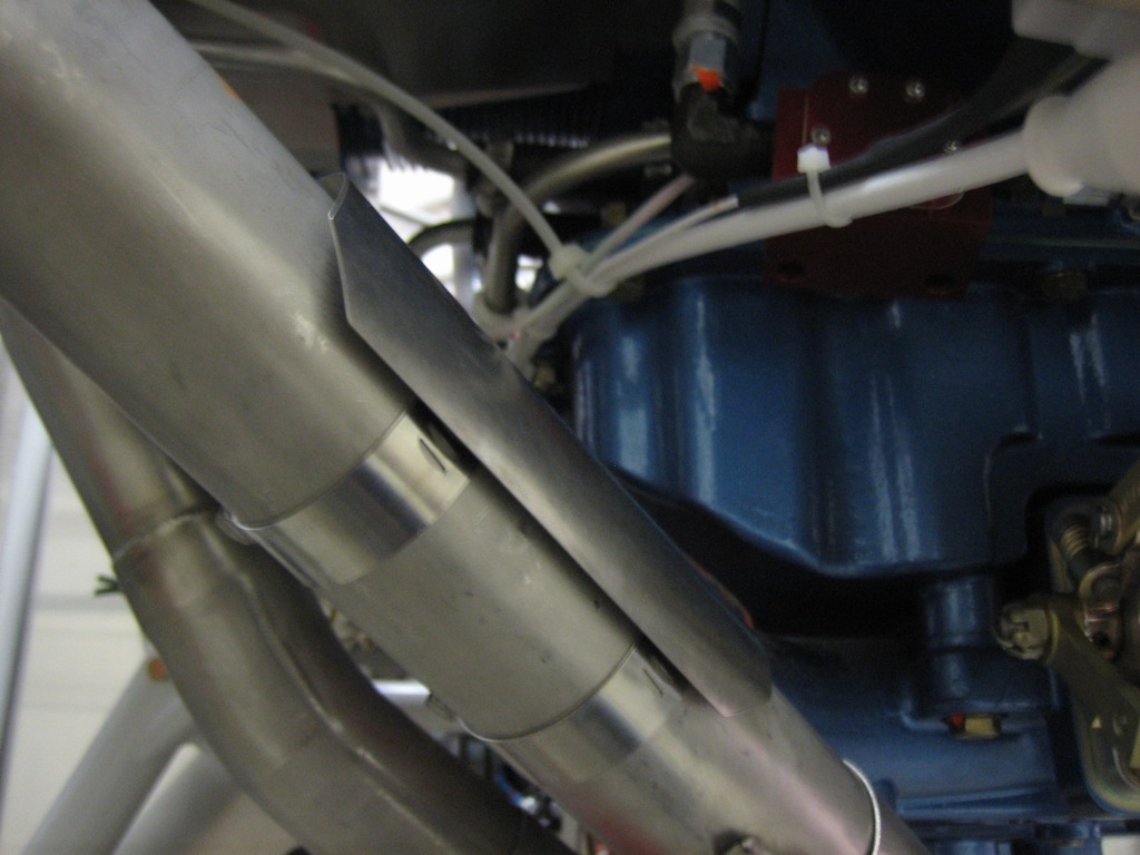
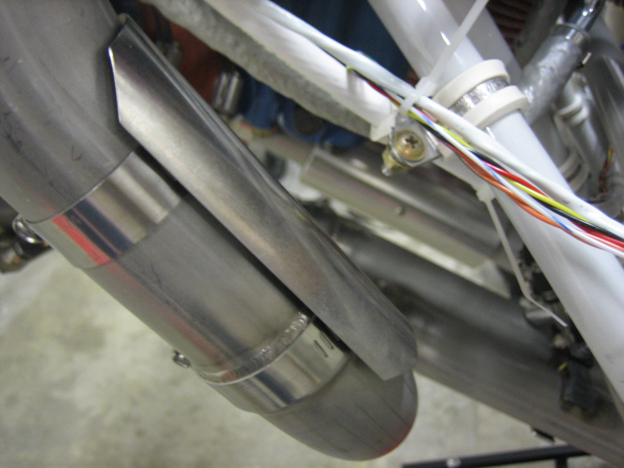
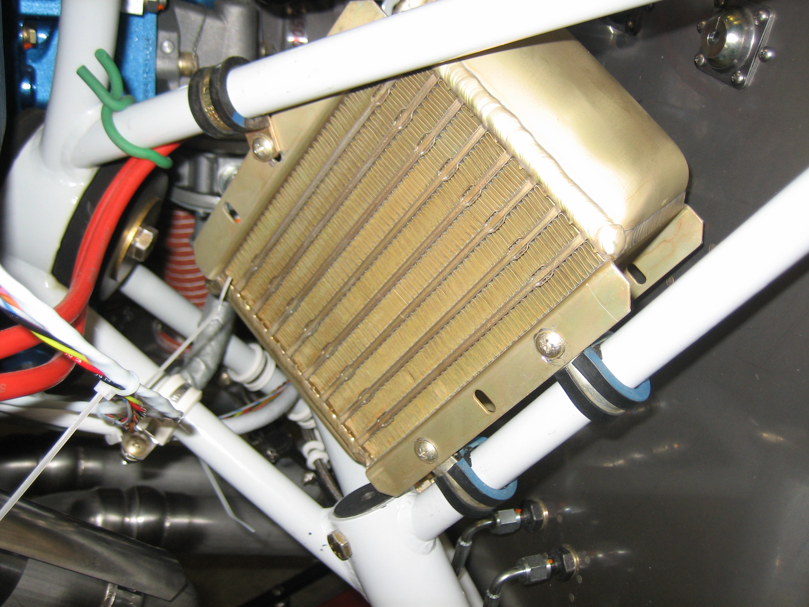
I also received a couple more 4″ exhaust heat shields.  I mounted one on the #4 pipe to protect the wires running through this area.

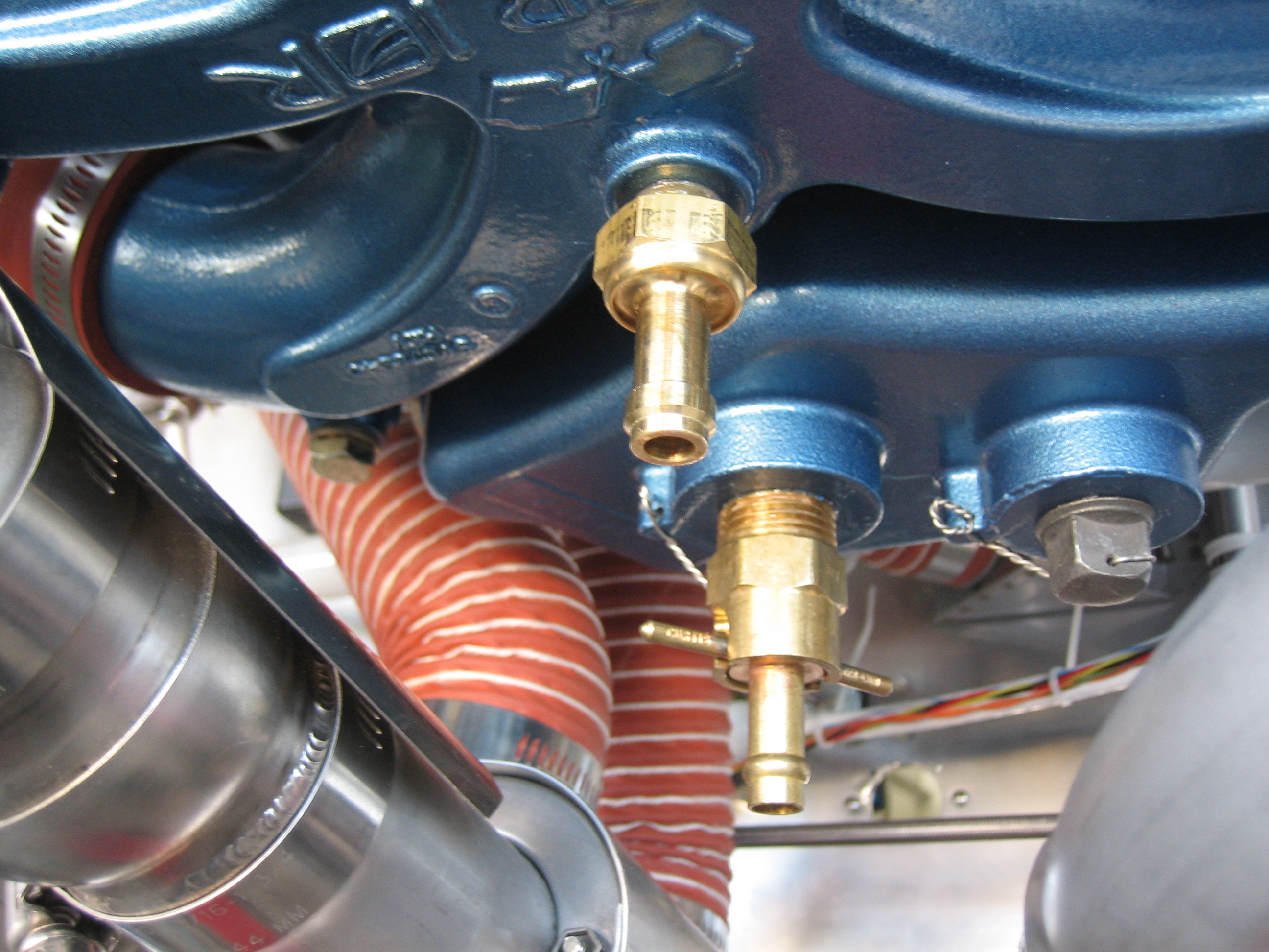
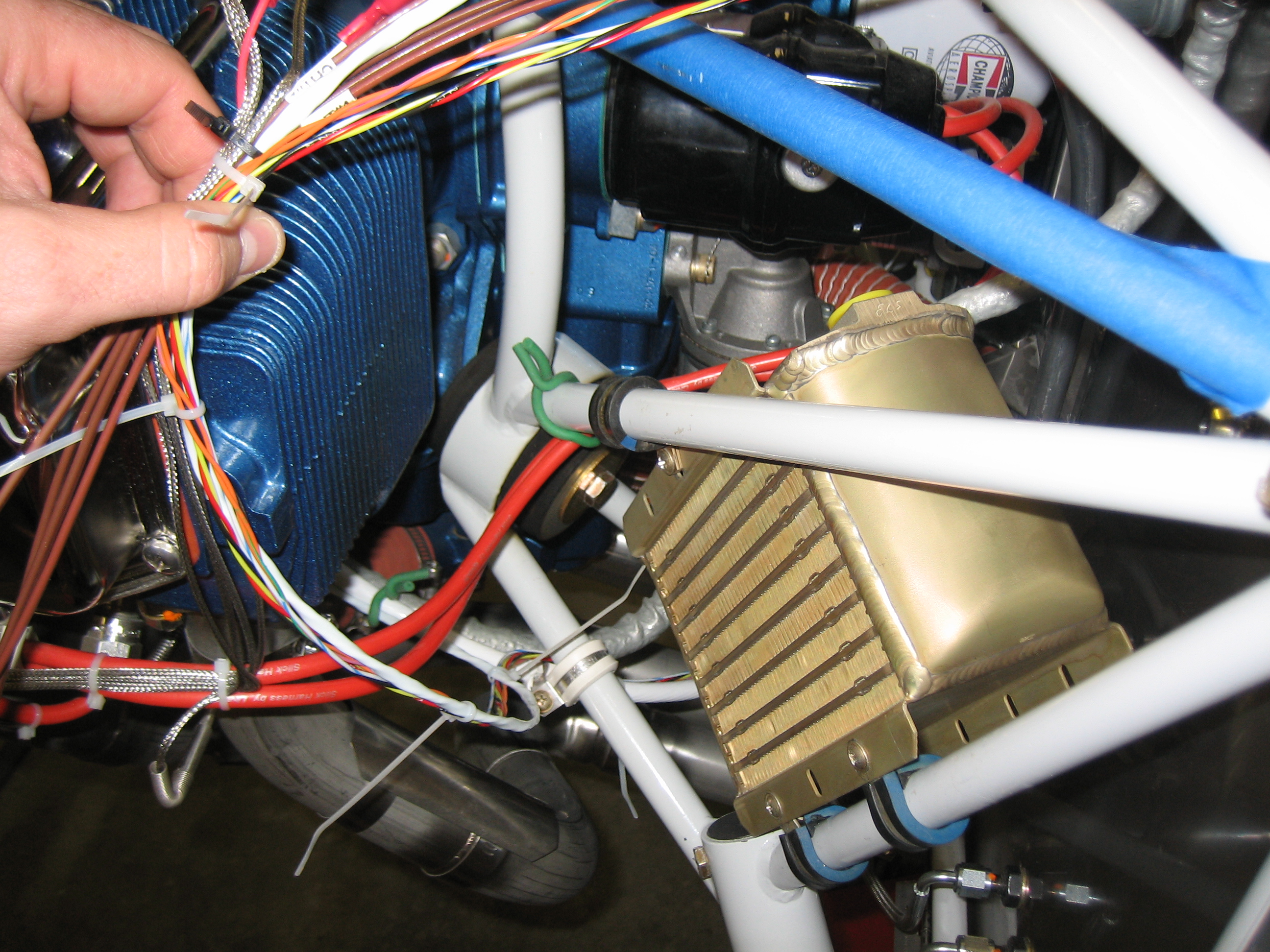
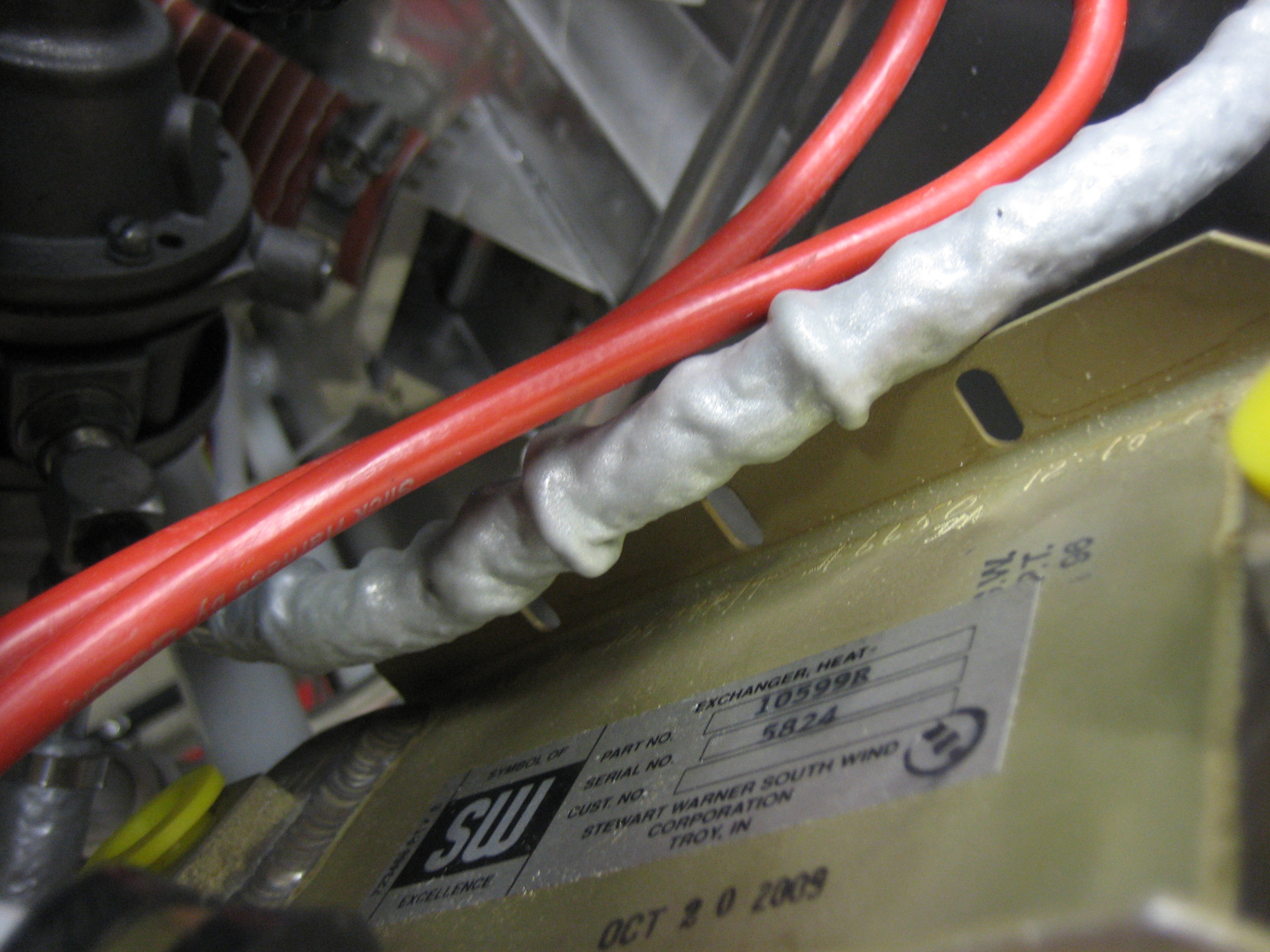
I also mounted two on the #1 pipe.  The first is just above the heat muff to protect the throttle cable.

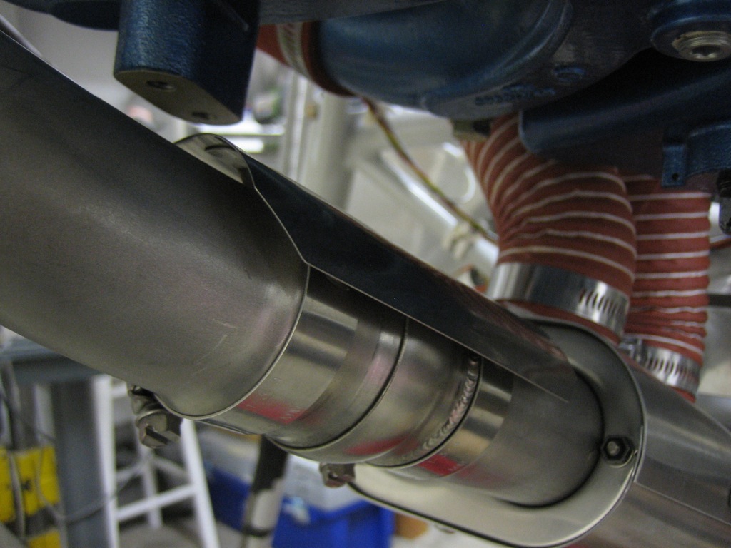
The second is a little farther up the pipe to provide some protection for the alternator wires and fuel flow sensor.

Installed Sniffle Valve, Oil Drain and Air Intakes

I installed the sniffle valve in the aft port in the intake manifold (the upper brass fitting).  This is a check valve that opens when on the ground to allow excess fuel or water that leaks into the engine manual to drain out of the bottom of the engine and onto the ground.  I also drained the preservative oil out of the engine and installed the quick drain plug into the sump and safety wired it.

I then mixed up some proseal and attached the air vents to the side of the fuselage.  I drilled a couple of holes for alignment purposes.  I’ll fill these in later with some filler.  A lot of builders pop rivet these on, but proseal is tenacious stuff and will hold these quite well.  This is the left side.

…and this is the right.

Experimenting With Oil Cooler Installation

I’ve been toying with various install locations for the oil cooler.  I would prefer not to mount it on the baffles for a couple of reasons.  First, it’s really tight there because of the size of the 10559R oil cooler.  Second, people already have problems with the baffles cracking due to the weight of the oil cooler.  Since this oil cooler is larger than typical, it will contain more oil and will therefore weigh even more than normal.  I would have to reinforce the baffles even more than builders normally need to carry the extra weight.

I tried various positions on the firewall, but things are really tight there.  There is one spot that could work, but it would require building a custom bracket and significantly reinforcing the firewall.  After playing with various mounting locations, I stumbled on the possibility of mounting it between two of the engine mount tubes.  I mounted it temporarily using a few adel clamps to see if it would work.  There’s a little bit of flex, but this is surprisingly strong.  I can move the entire plane by pushing and pulling on this.  If I go with this location, I’ll move it down a little bit and fabricate a bracket that lets me use two adel clamps on the top flange to prevent twisting.  This will give me a little more clearance for the control cables as well as make the upper engine mount tube be a little move out of the way.

You can see that there is plenty of room between the back of the engine and the oil cooler.  I will mount a flange on the back of the baffles (either 3″ or 4″) and run some scat tube down to a custom plenum that I will fabricate to direct the air through the oil cooler.  I want to sleep on it and run it by the folks on vansairforce.net to make sure there aren’t any issues with this plan.

The fuel pressure line runs right by the back side of the oil cooler.  I’ll install an adel clamp here to space the line a little bit away from the oil cooler flange.

Worked on Armrests

The armrests are pretty flimsy as designed.  I’m using some 0.063″ angle to reinforce them.  I used a router to radius the outside corner so that it can tuck into the angle on the armrest.  I drilled them to the flange and will eventually also drill them to the top surface of the armrests.

I also fabricated four of these little supports that will rivet into the bulkheads at each end of the armrests to transfer the load directly into the bulkheads instead of through the wimpy flanges on the armrests.

Here’s how these will mount.  Any load on the armrests will be transferred into the 0.063″ angle.  The angles will sit directly on top of the supports to transfer the load into the bulkhead.  Without these, that little flange just above the angle would have to carry the load.

Installed Right Cap Strip

I riveted the right cap strip in place.  Doing this many pop rivets in a row with a hand pop-riveter is a killer on the hands and forearms.  I really wish I had purchased a pneumatic pop-riveter near the beginning of the project.  There are probably not enough remaining pop rivets left on the plane to justify purchasing one now though.

Here’s a closeup of the forward armrest support.

And here’s the aft armrest support for the right side.  I installed this with solid rivets since I had access to the back side.

Finished Drilling Armrest Reinforcement Angles

I finished drilling and deburring the reinforcement angles to the armrests.  Rivets will be spaced on roughly 1″ intervals on the top and side of the angles.

Here’s the angle that will tuck up under the armrest.  I just need to countersink these holes and dimple the armrests and these will be ready to rivet.