Torqued Engine Attach Bolts

I’ve been deburring and countersinking pieces of the cabin frame, but this is boring and not worth pictures.  I did decide I’d go ahead and torque and cotter pin the engine attach bolts for some reason today.  You can’t get a torque wrench on these, but Van’s instructions are basically to tighten these down firmly against the internal spacer in the mount.  You can feel when these bottom out against the spacer.  I then tightened them slightly more to align the cotter pin slots.  Getting the cotter pins installed in the top two bolts was fairly trivial.  The bottom two were kind of a pain with everything in the way.  Do yourself a favor and install the cotter pins as soon as you hang the engine and not after the exhaust, control brackets, wires, etc. are in the way.

Installed Master Cylinder Fittings

I received the AN822-3D fittings from Aircraft Spruce today and installed them in the master cylinders.  I then installed the hoses from the brake fluid reservoirs onto the upper fittings.  I searched everywhere for these fittings in black, but could only find them in blue.  I did find AN822-4D fittings in black, but I didn’t want to use 1/4″ lines here if I could avoid it.  I even briefly thought about having some re-anodized in black, but that would be ludicrously expensive and I couldn’t have re-anodized the hose end fittings.  I also replaced the AN816-4D fittings I previously installed in the parking brake with AN816-3D fittings.  Finally, I measured for the final brake hoses from the master cylinders to the parking brake.  I need to put in another order to Bonaco soon for these hoses as well as the manifold pressure hose and possibly the remaining fuel hoses.

Finished Cabin Frame

I finished deburring and countersinking the cabin frame components this morning.  When our two year old went down for her nap, I came back out and primed all of the components and then started assembly.

I’ve seen several builders complain that their cabin frames came out wider or narrower than intended.  I think this is likely due to the slight amount of play in the splice plate rivet holes.  Although the play is tiny at the splice plate (in the middle joining the left and right halves of each channel), the amount of play at the ends of the channel will be much more (easily 1/4″ or more).  To help ensure that this doesn’t happen to me, I clamped the channels back in the sizing jig before squeezing the splice plate rivets.

After the front and back channels are joined with the splice plates, the straps can be clecoed into the forward channel so that solid rivets can be squeezed here.  After all solid rivets are squeezed, the aft channel can be installed and blind rivets can be squeezed.

I didn’t get any more in process pictures, but here’s the completed cabin frame.

Here you can see the solid rivets in the forward channel (lower) and blind rivets in the aft channel (upper).  After everything was riveted, I measure the channel and I was only 1/32″ narrower than the plans called for.  This appears to be more accurate than most people end up with.

Started Mounting Cabin Frame

I started today by fitting the attach angles to the bottom of the cabin frame.  These two angles are clamped to the outer edges of the channels and then drilled to each other.  After these were drilled, I countersunk the bottom face and riveted them together.

To ensure that the angles were mounted in the right position, I clamped some scrap angle to the longerons with some pieces of hinge material underneath to tip the angle back to match the slope of the side skin.

Here you can see that the angle is flush with the skin.

I then used some scrap 0.063″ aluminum (the thickness of the cabin frame channels) to space the attach angles back so that the forward edge of the cabin frame will be flush with the side skin.

I then drilled/reamed the attach angles to the rest of the structure.

I then temporarily installed the cabin frame to see how it fit.  As I measured yesterday, it was slightly narrow, but a small amount of pressure from a clamp could spread it into position.  The attach angles hang over the sides of the longerons.  I marked the overhang and then removed the attach angles to start filing them down.

I took a break from the filing and laid out a cover for the cabin frame channel.  I’m going to be installing a cover on this channel so that I can install a cabin light into it.

Finished Cabin Frame Attach Angles

I finished trimming the cabin frame attach angles so that they’re flush with the sides of the fuselage.  I alternated between using the vixen file and the disc sander, then finished up with the scotchbrite wheel.

Here you can see how the aft top skin lays flush against the side of the angle.

Here’s the cabin frame clamped as low as it can currently go.  It’s still about 3/16″ of an inch high right now, but I actually want it to end up a little high so I can get more headroom.  One of the engineers at Van’s said the cabin frame could be moved up at least 1/4″ without any problems.  I want to double check this before permanently mounting the cabin frame though.

Here you can see that the side skin is perfectly aligned with the cabin frame (both angle and longitudinal position).

I also installed the cabin frame brace to correctly position the cabin frame.  It’s clecoed in the back, but only clamped in the front.  I don’t want to drill this until I’m sure of the position.

Lowered Cabin Frame

I had the cabin frame clamped 1/4″ above the location specified in the plans.  I looked over the canopy plans as well as all of the fastener positions.  This is the only issue I ran into.  The lower #8 screw through the aft top skin would penetrate the cabin frame only 3/16″ above the lower edge.  Since this hole needs to be drilled out to #29 and then tapped for a #8 screw, I didn’t think this was enough.  I couldn’t lower the cabin frame much without the outer edges running into the inner radiuses of the attach angles.  I didn’t get a picture of it, but I made a relief cut and radiused the edge to allow the cabin frame to drop down.

Here’s the cabin frame dropped to the height specified in the plans.  There’s now approximately 7/16″ edge distance on this hole which would be more than plenty.  I’m probably going to try and move the canopy up to the minimum edge distance for this hole to get as much headroom as possible.  A #29 hole is 0.136″ diameter.  1.5D edge distance would require 0.204 edge distance which is just over 3/16″.  If I increase that to 1/4″ to get a little more than minimum, then I’ll end up with a cabin frame about 3/16″ above normal.

Finished Attaching Cabin Frame

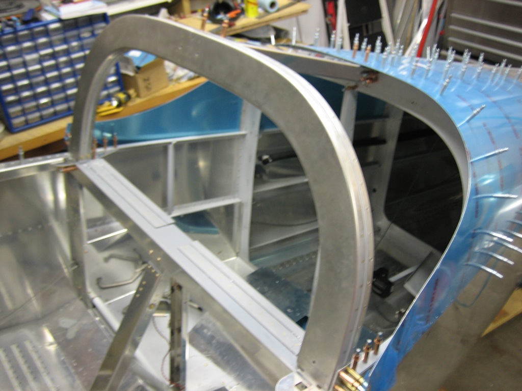
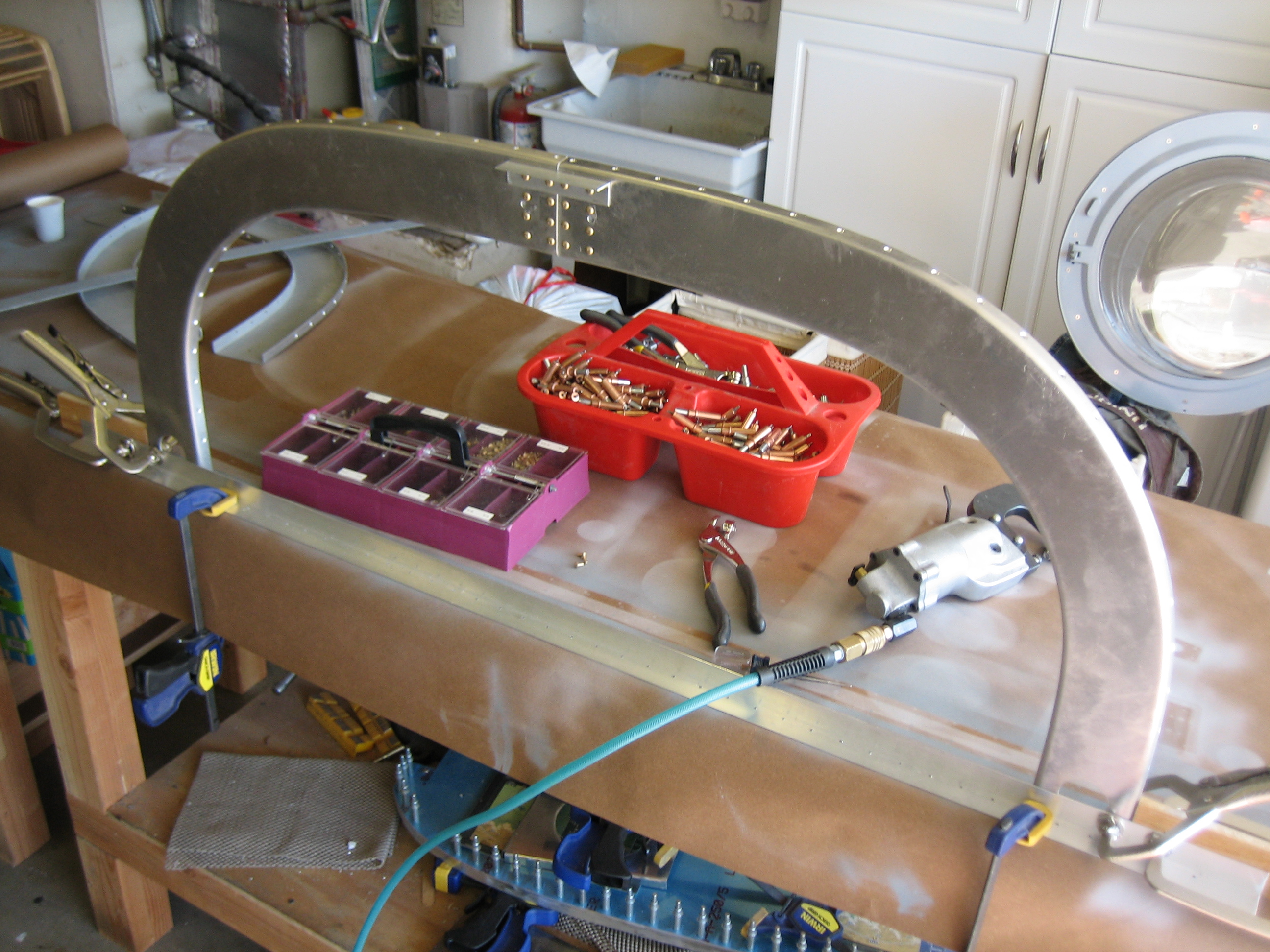
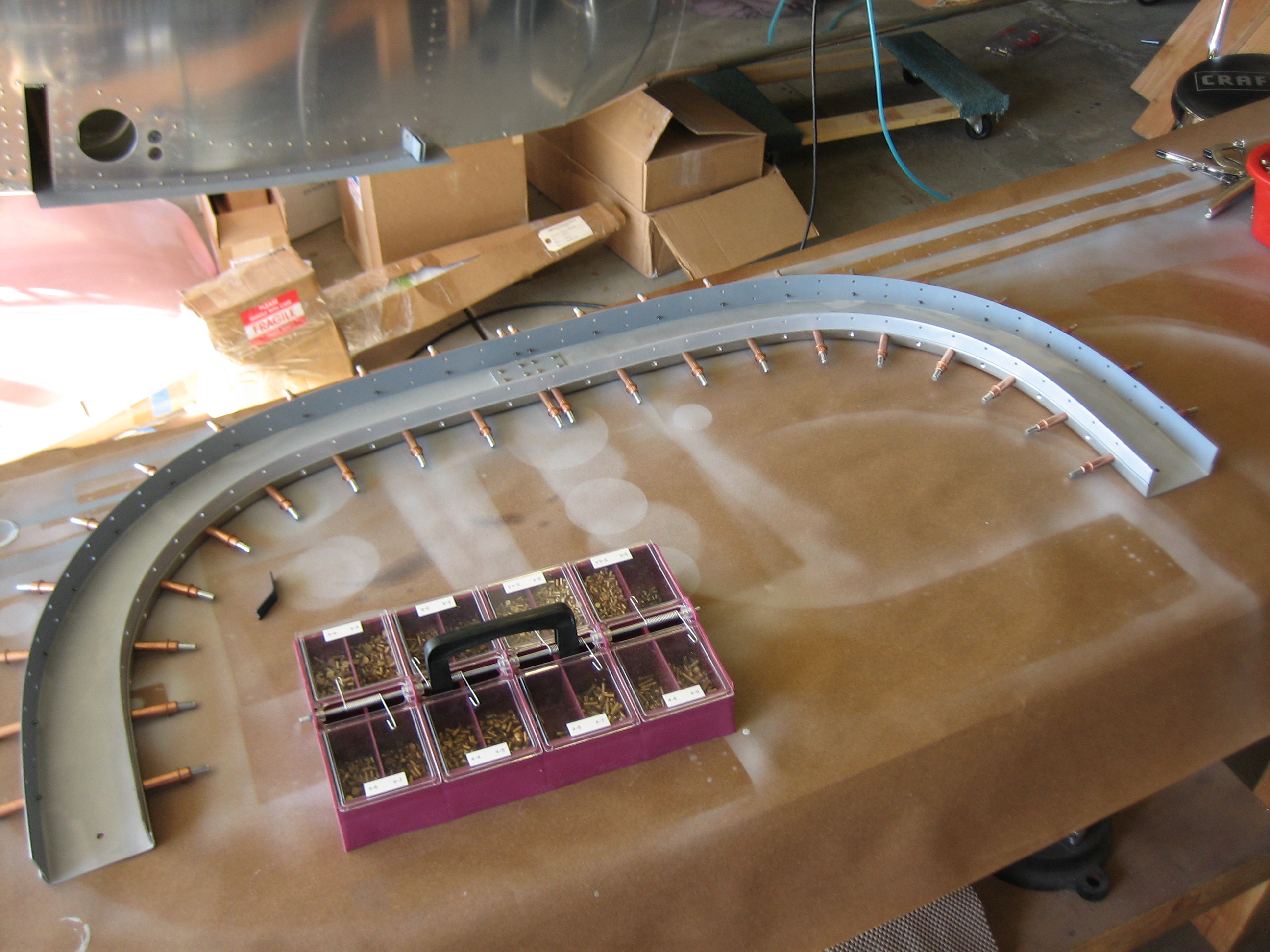
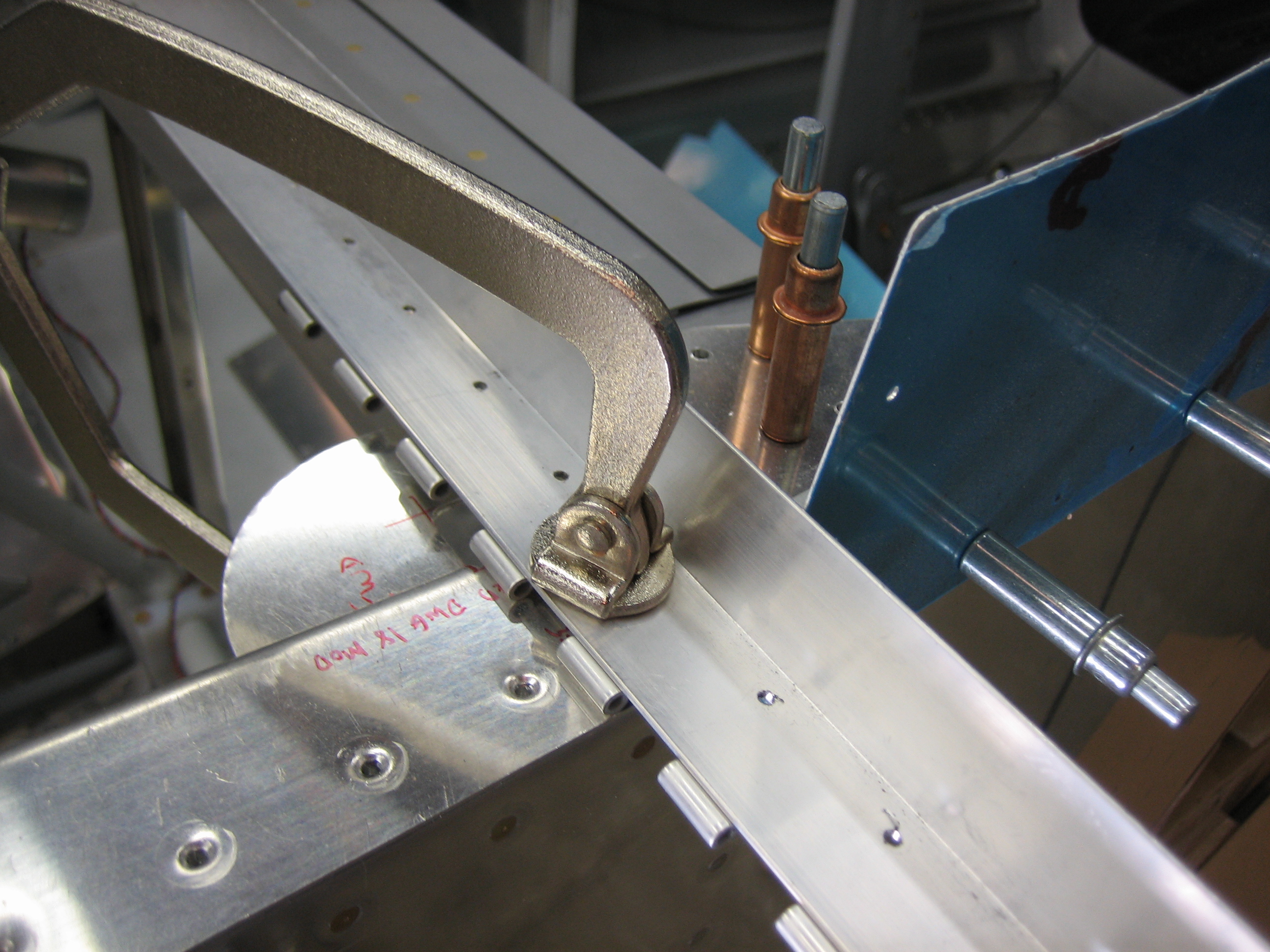
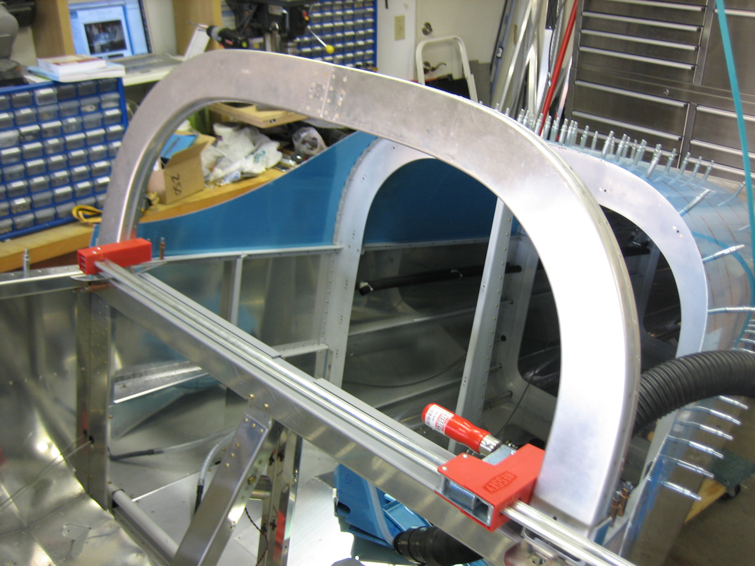
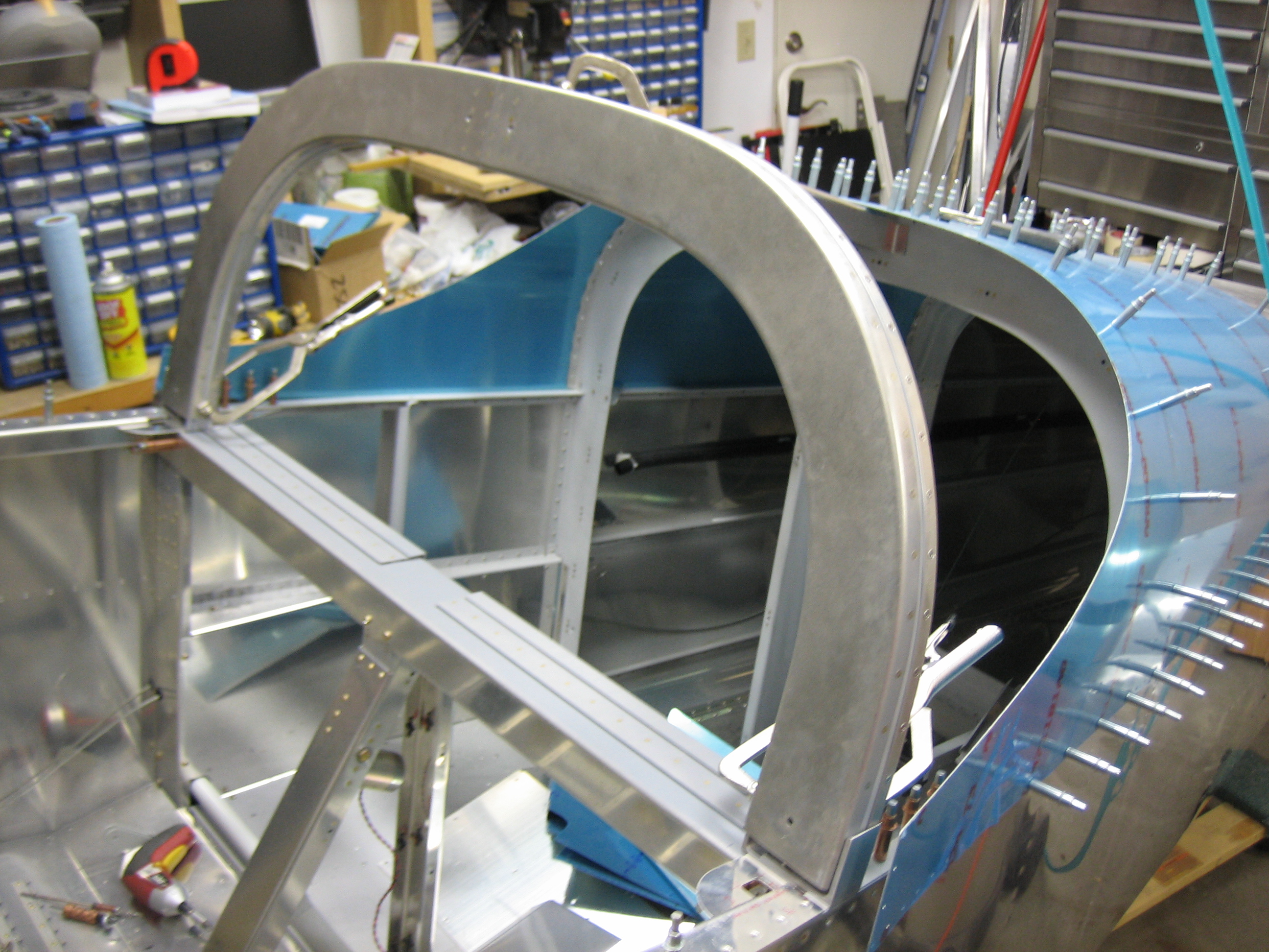
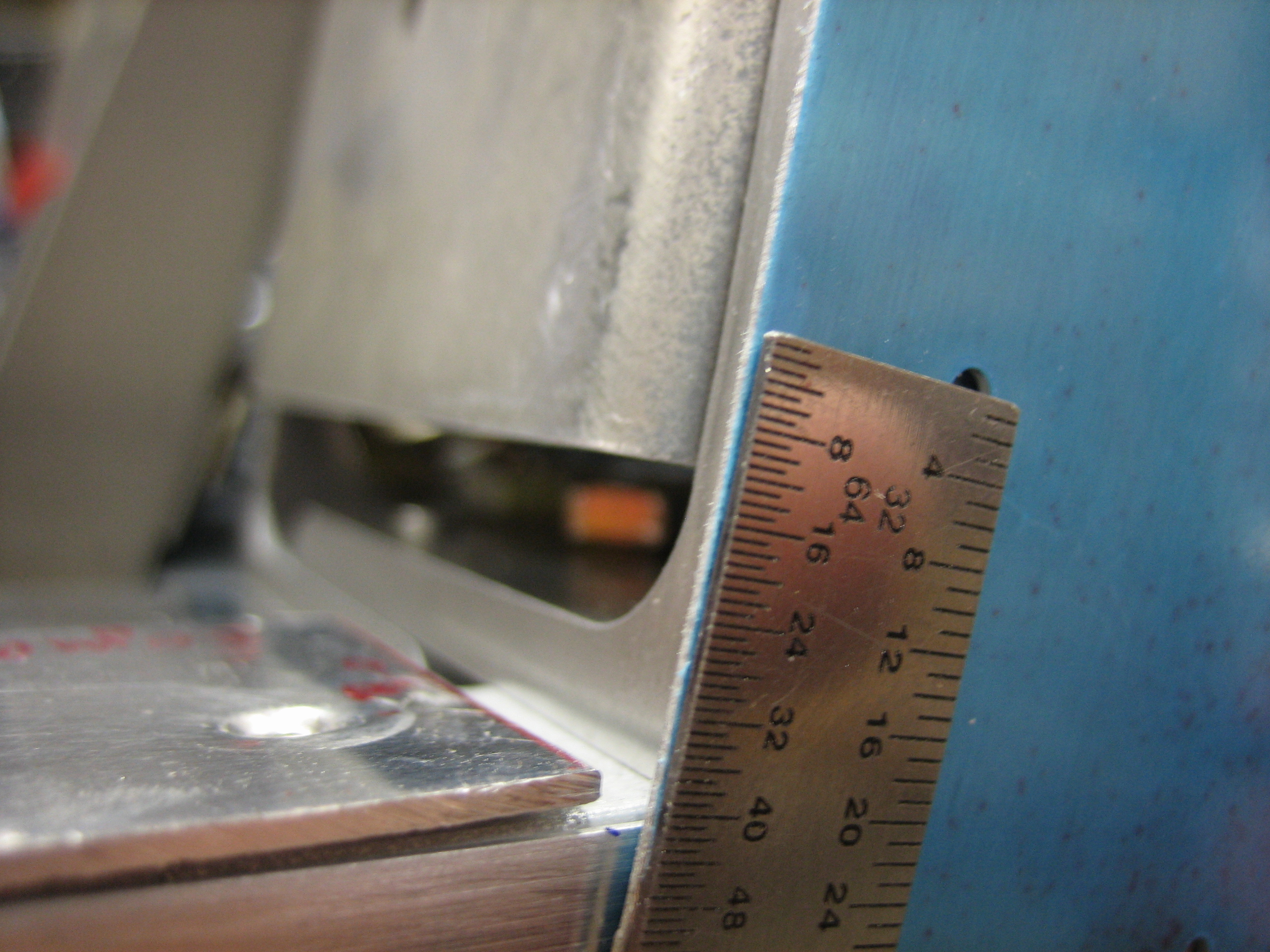
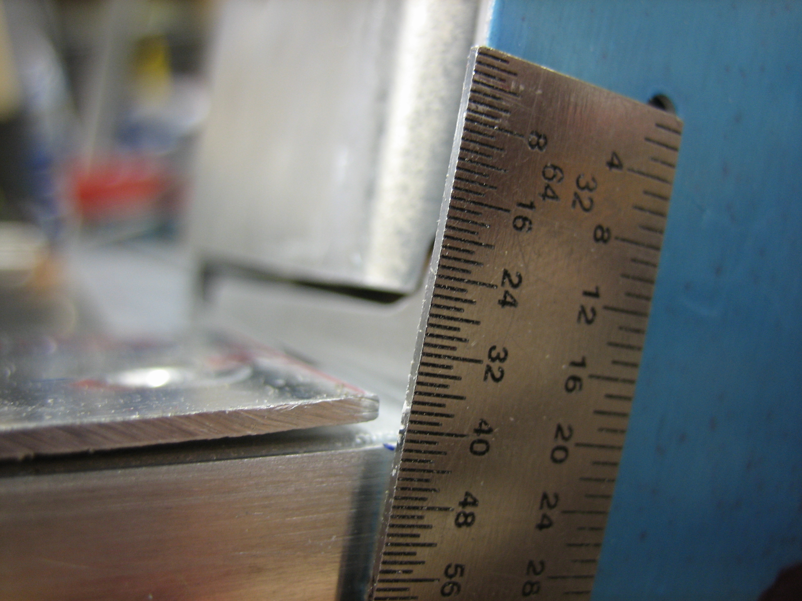
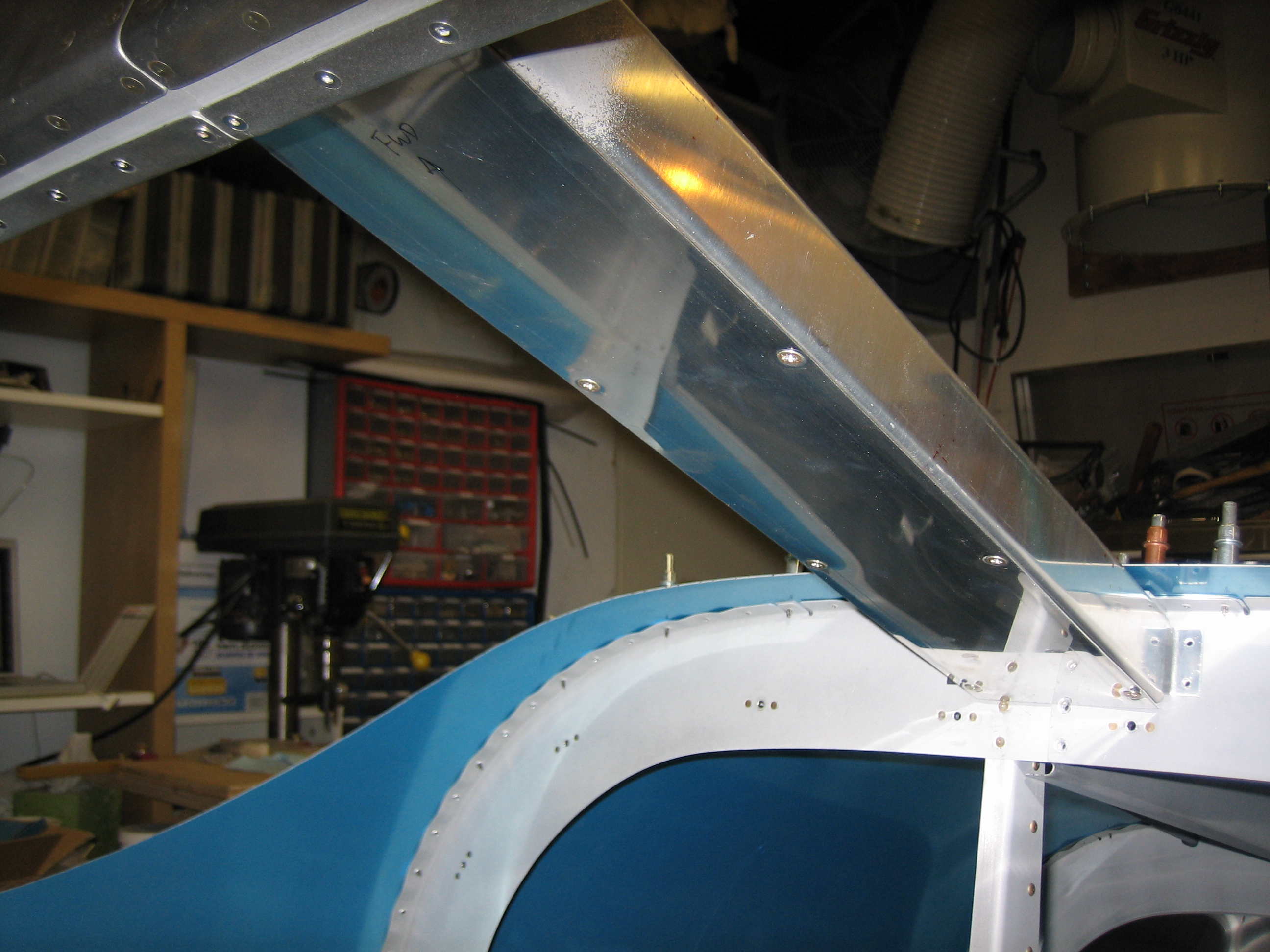
I ended up positioning the cabin frame exactly where the plans specify, 17 7/8″ up from the aft canopy decks.  After clamping everything securely in position and double checking the measurements, I started drilling.  First up is to drill the aft edge of the channel to the top skin and F-706 bulkhead as well as to drill the channel flanges to the bulkhead.

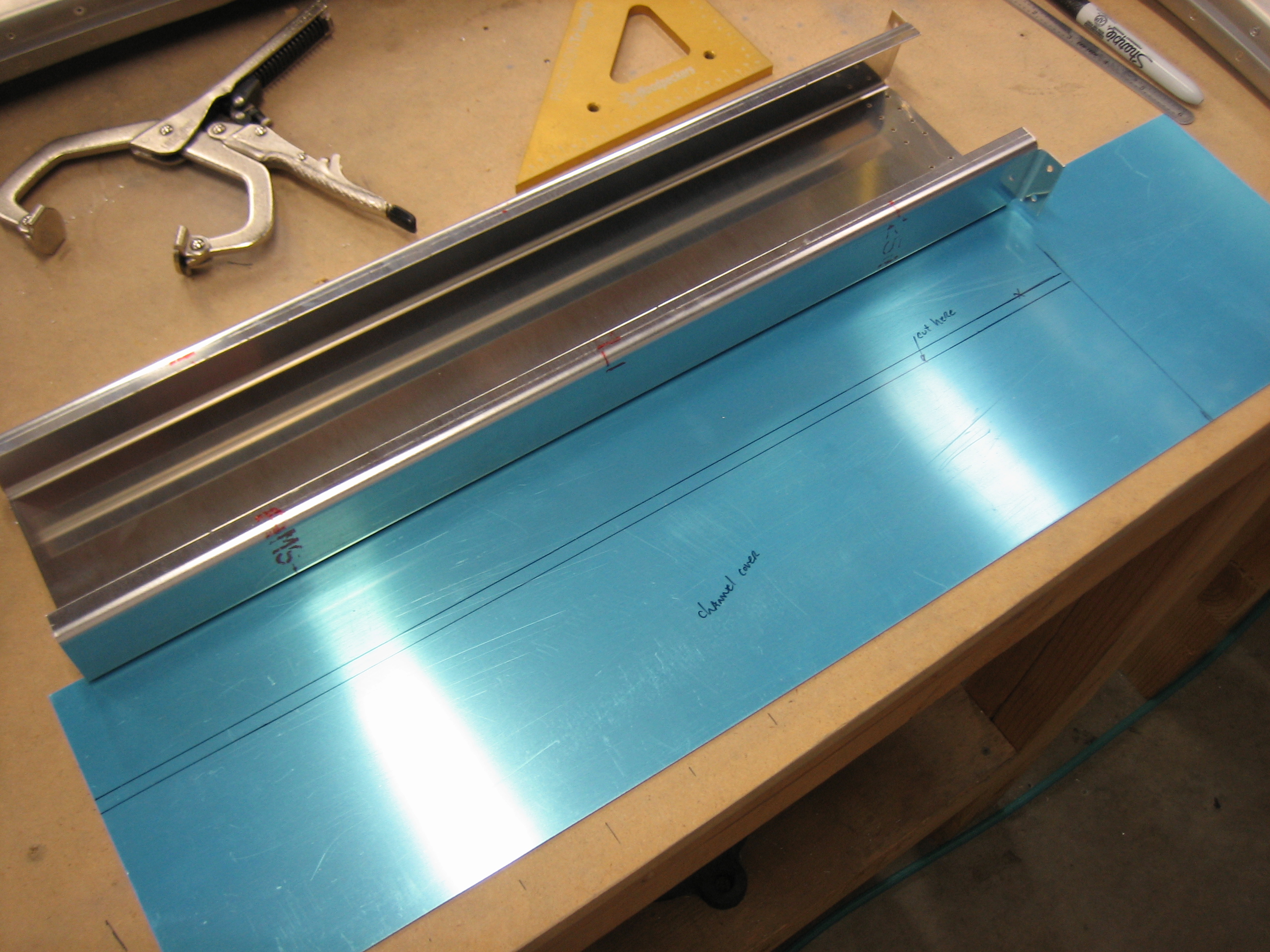
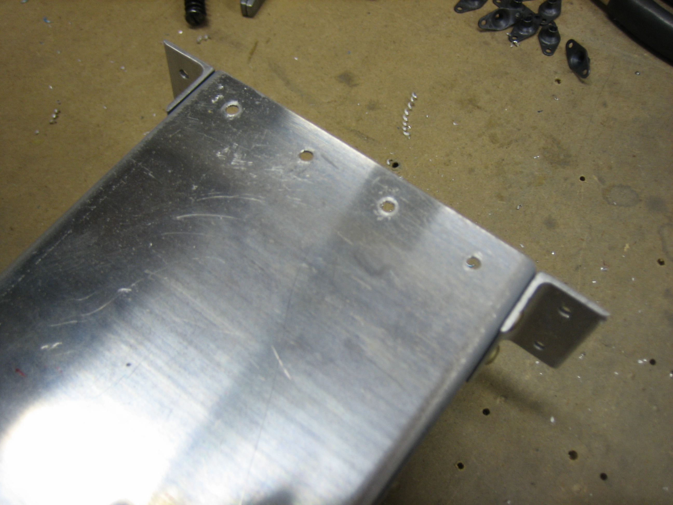
Next up is to layout the four holes that attach the channel to the cabin frame.  I drilled these to #40 first using the fan and then opened them up to #30.

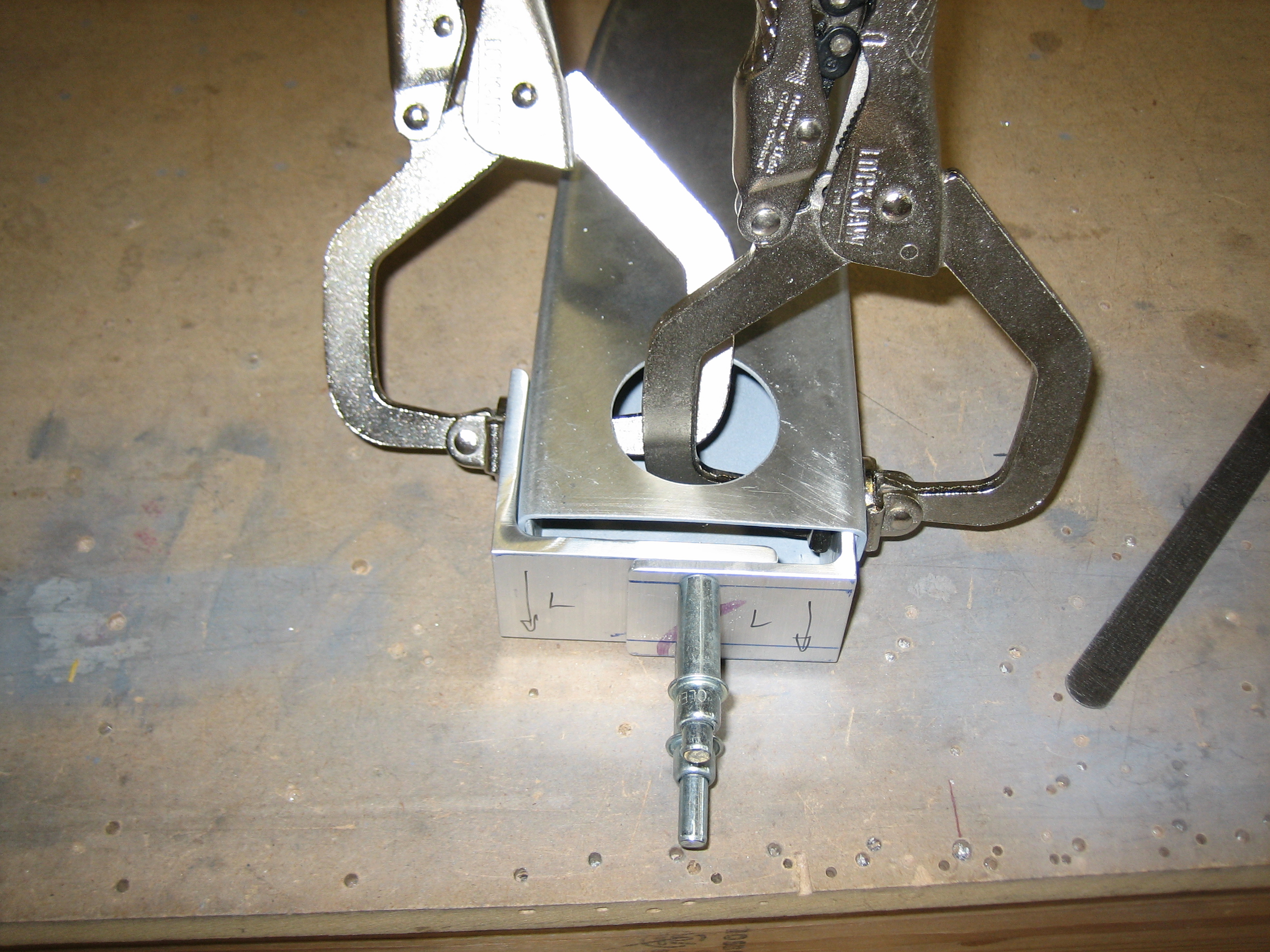
I also drilled the side angles to the channel and cabin frame.

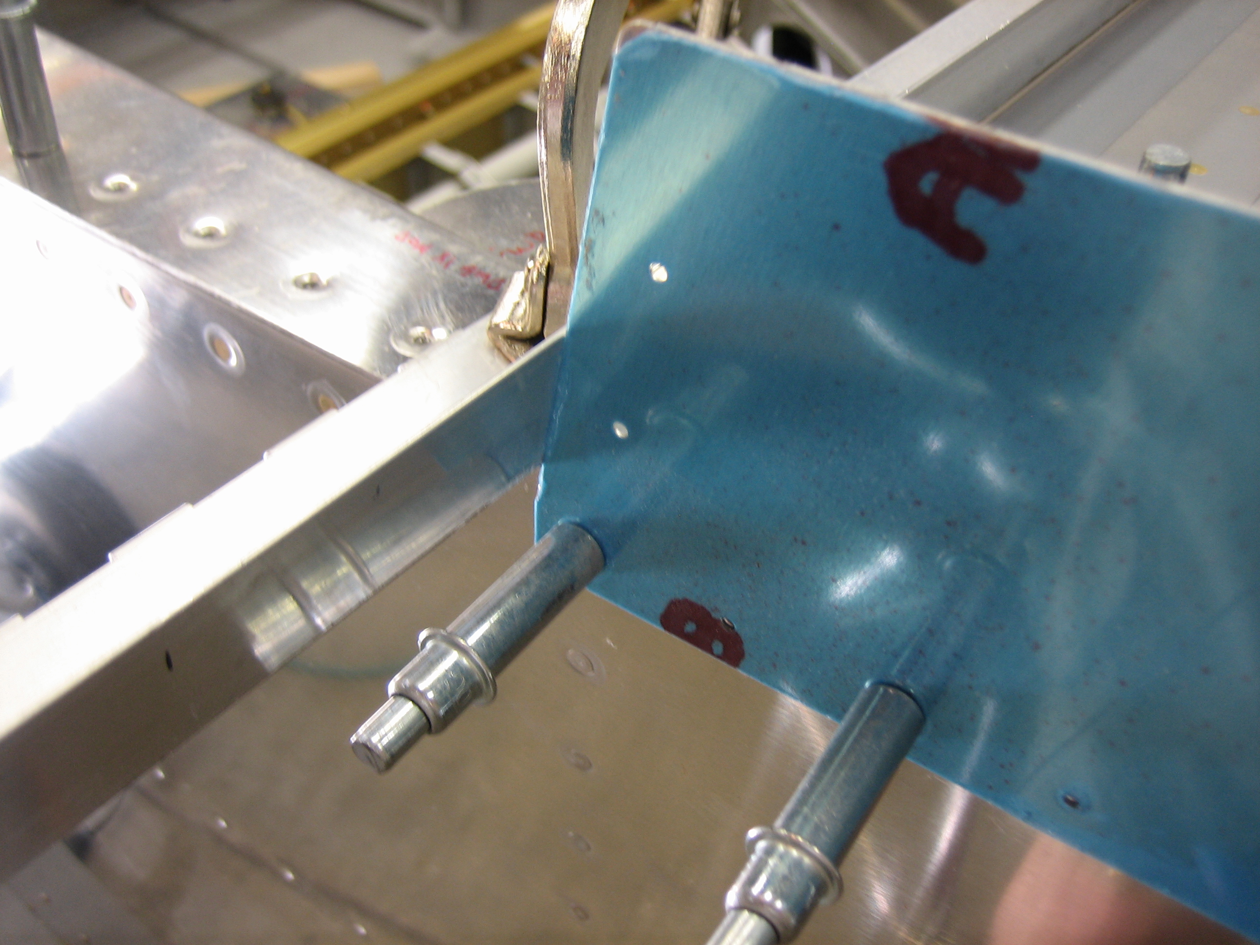
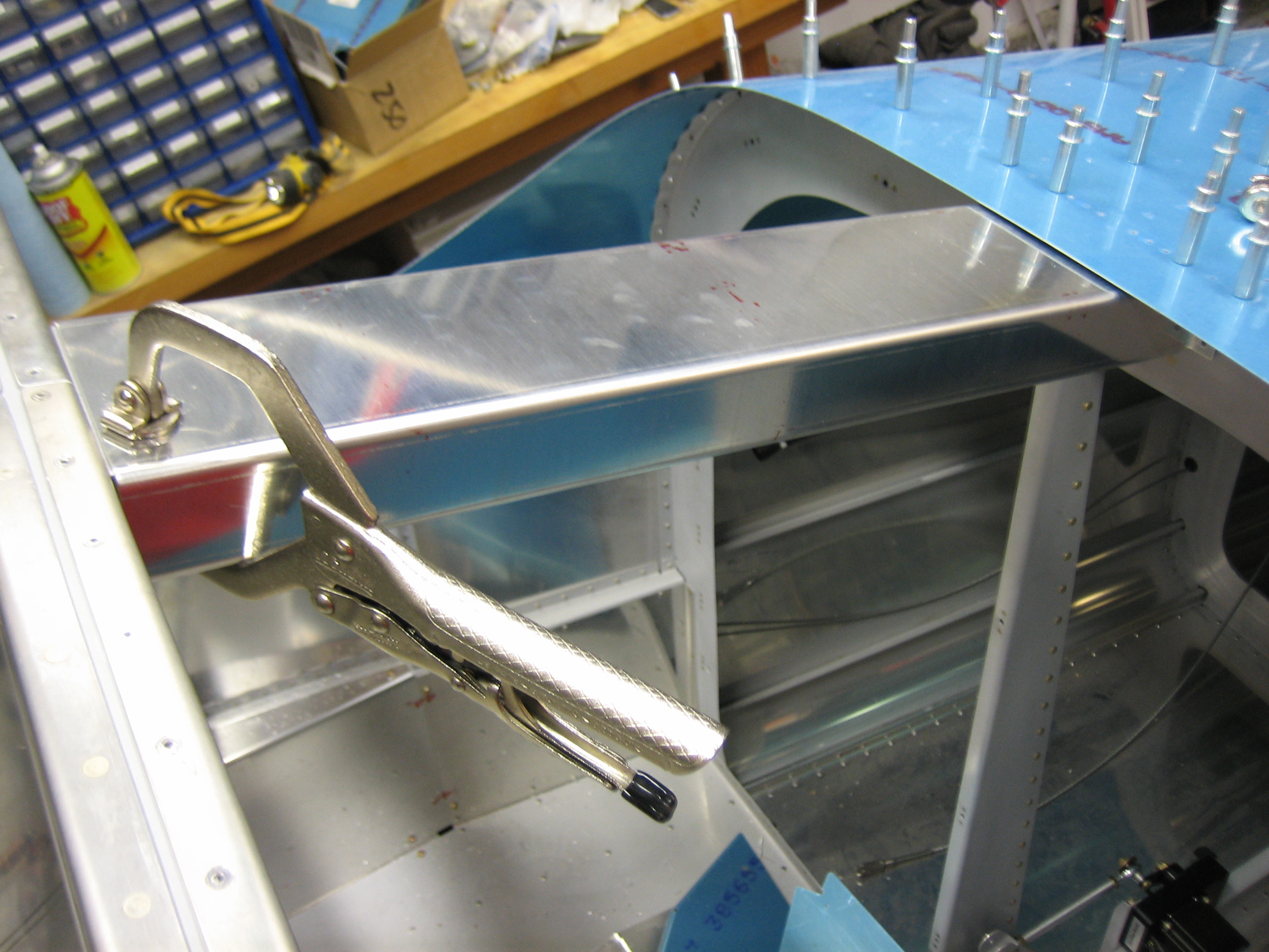
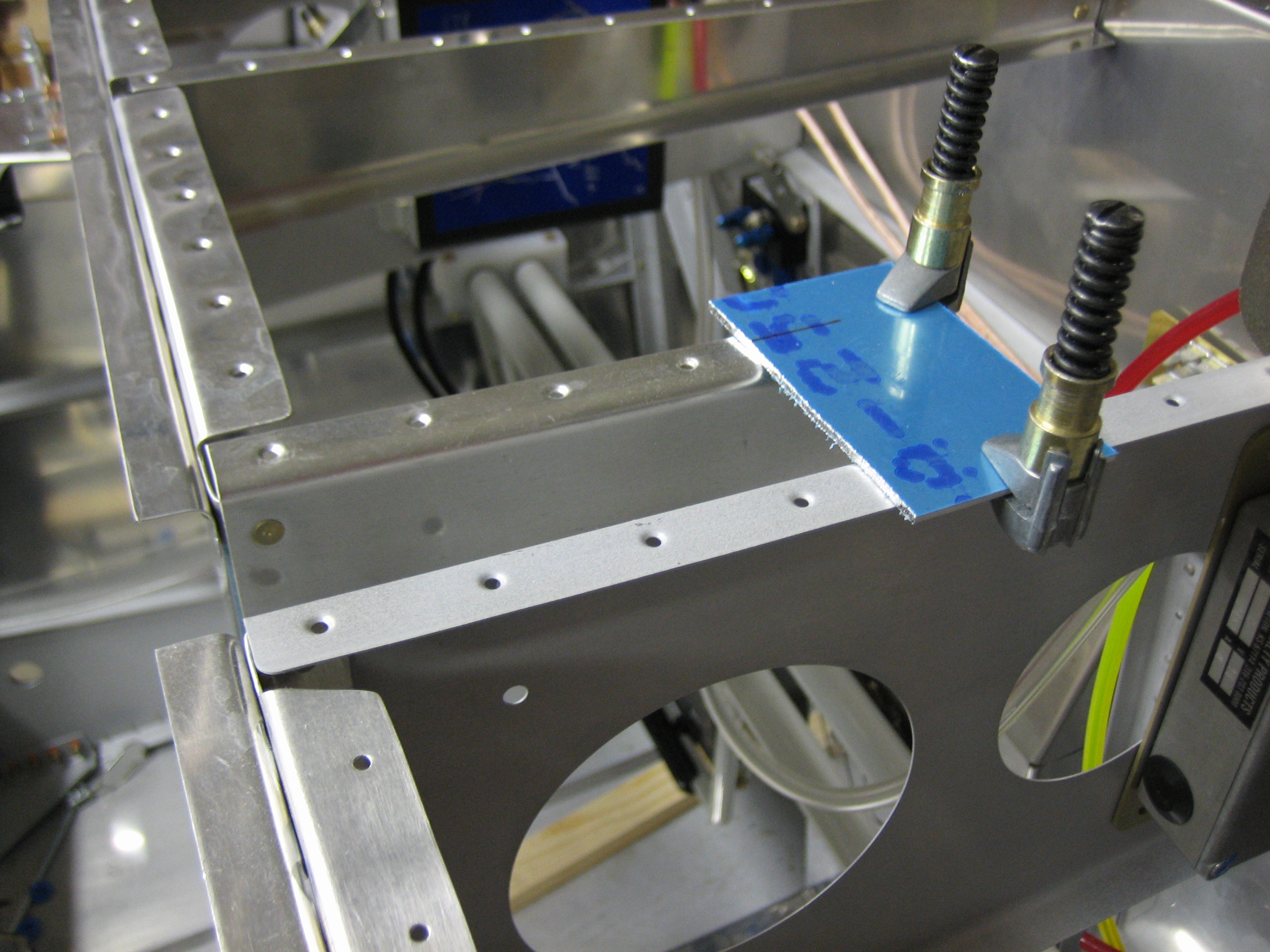
I used a couple of c-clamps to squeeze down the cabin frame where it had flared out near the bottom and was thicker than 1.5″.  I then drilled the forward holes through the side skins and through the attach angles and cabin frame.  These were initially drilled to #30 so that they could be clecoed.

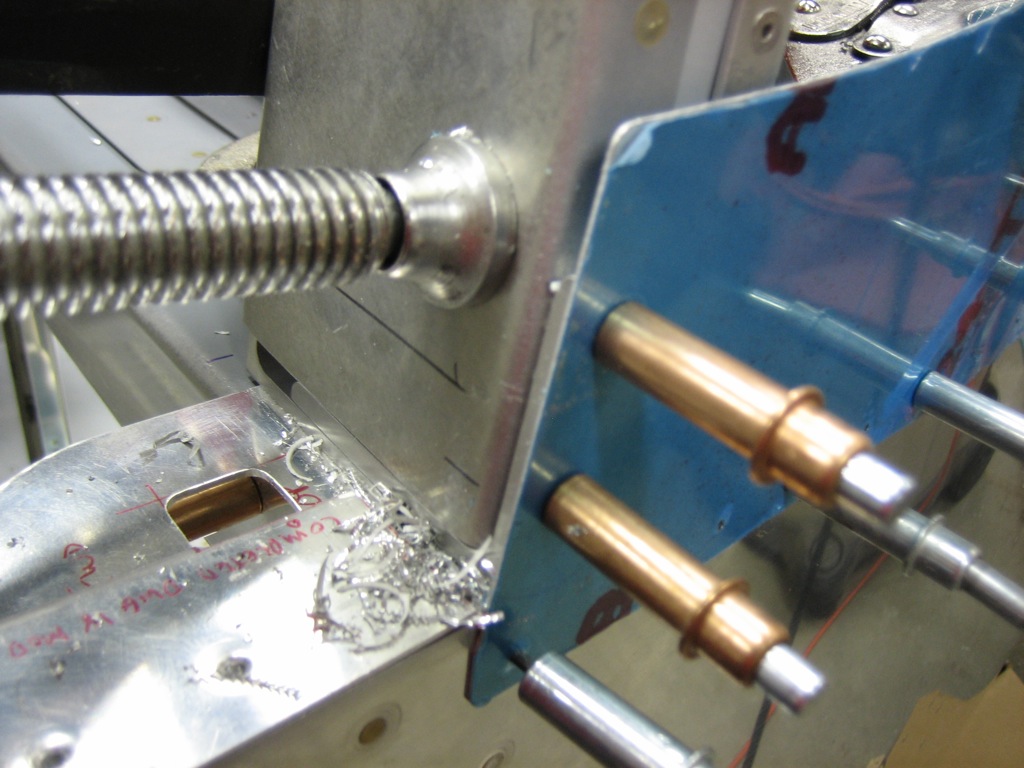
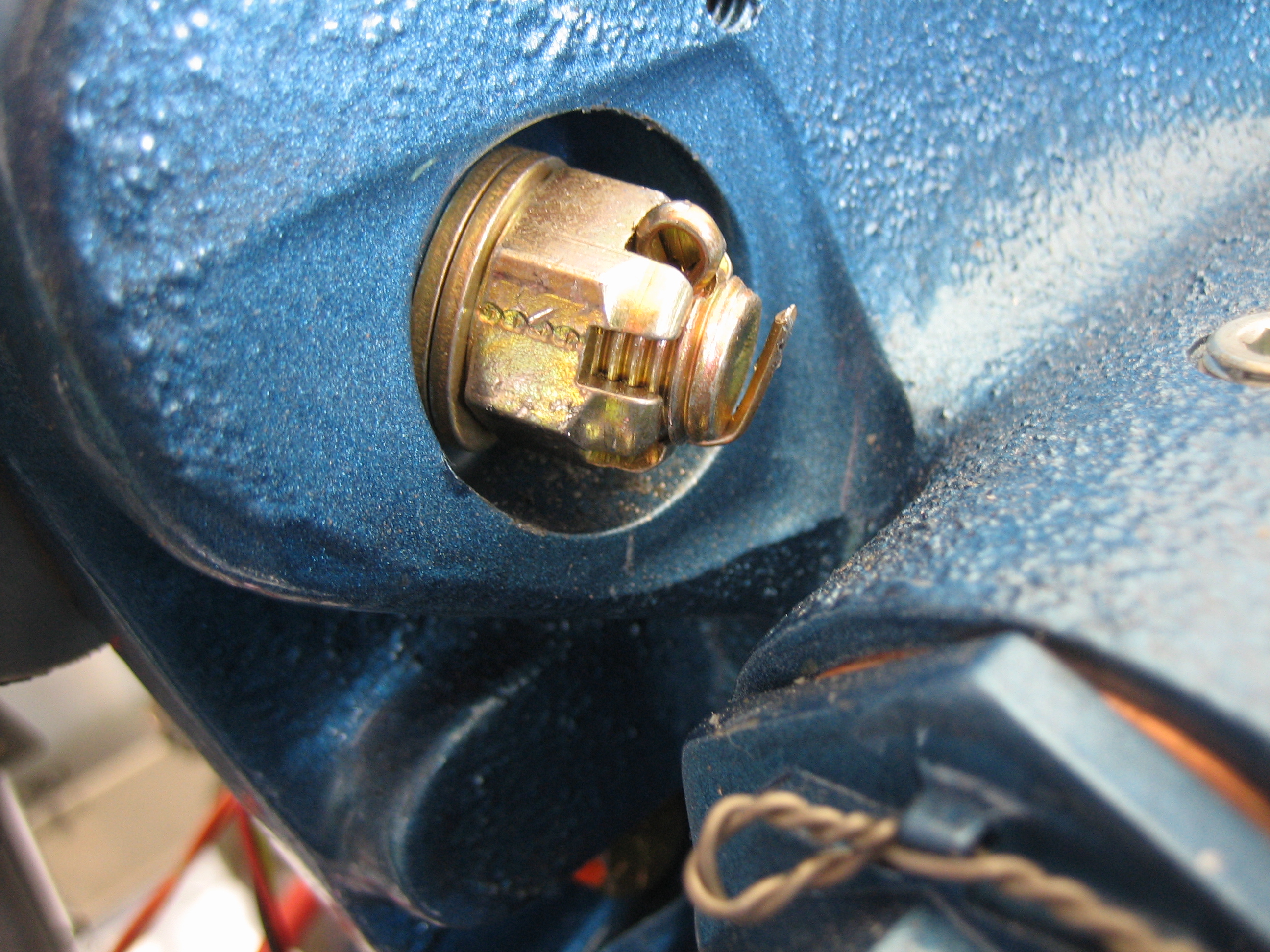
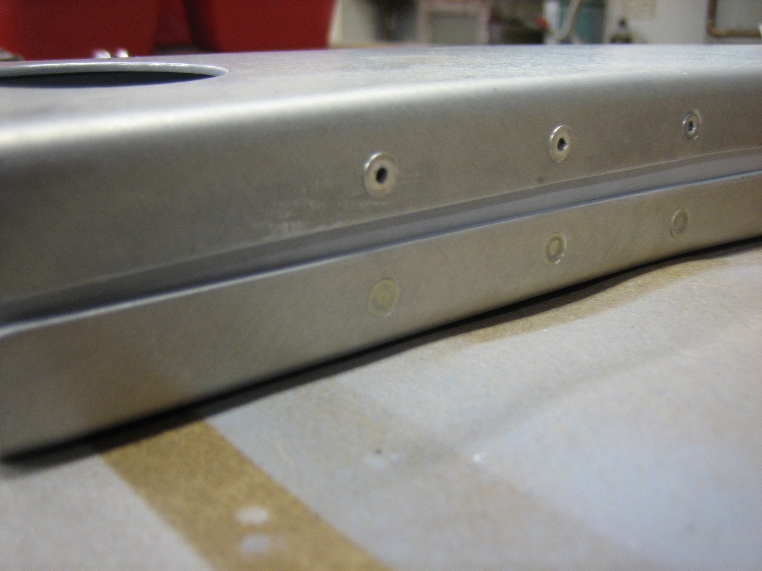
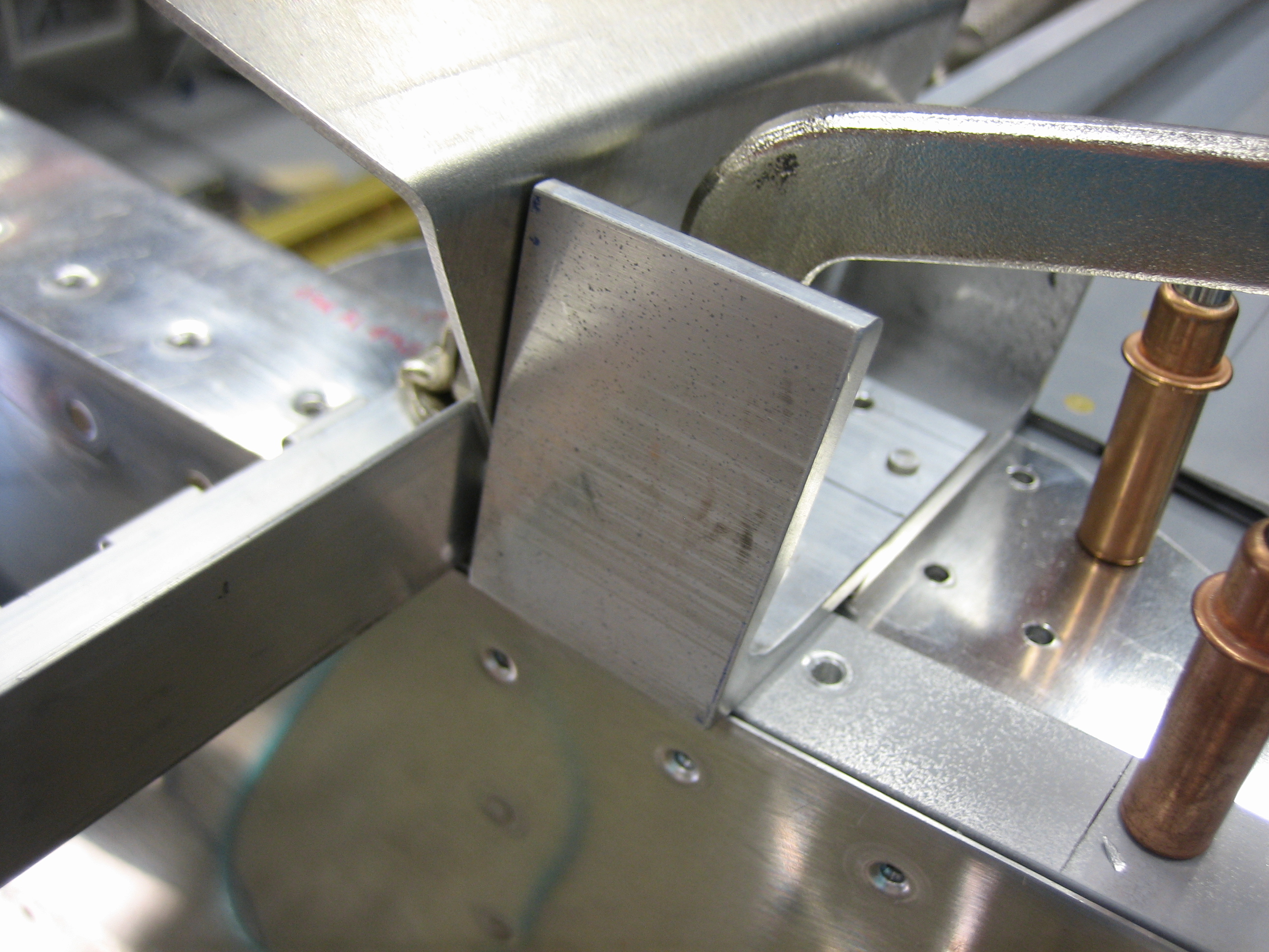
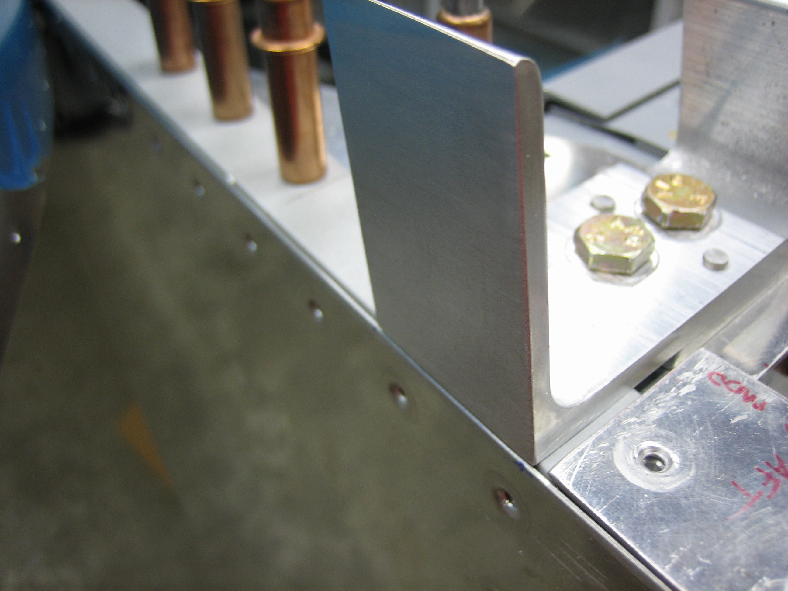
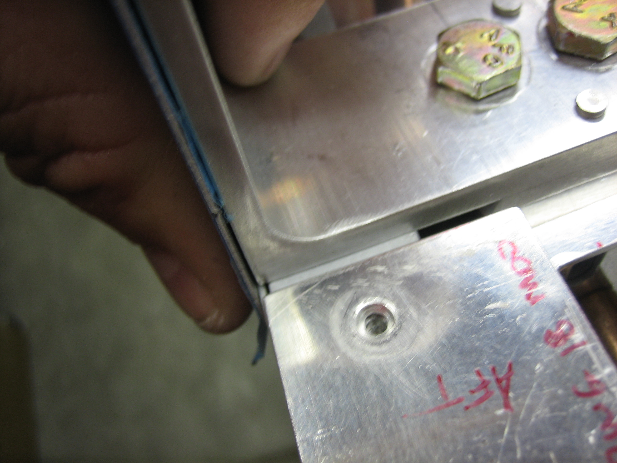
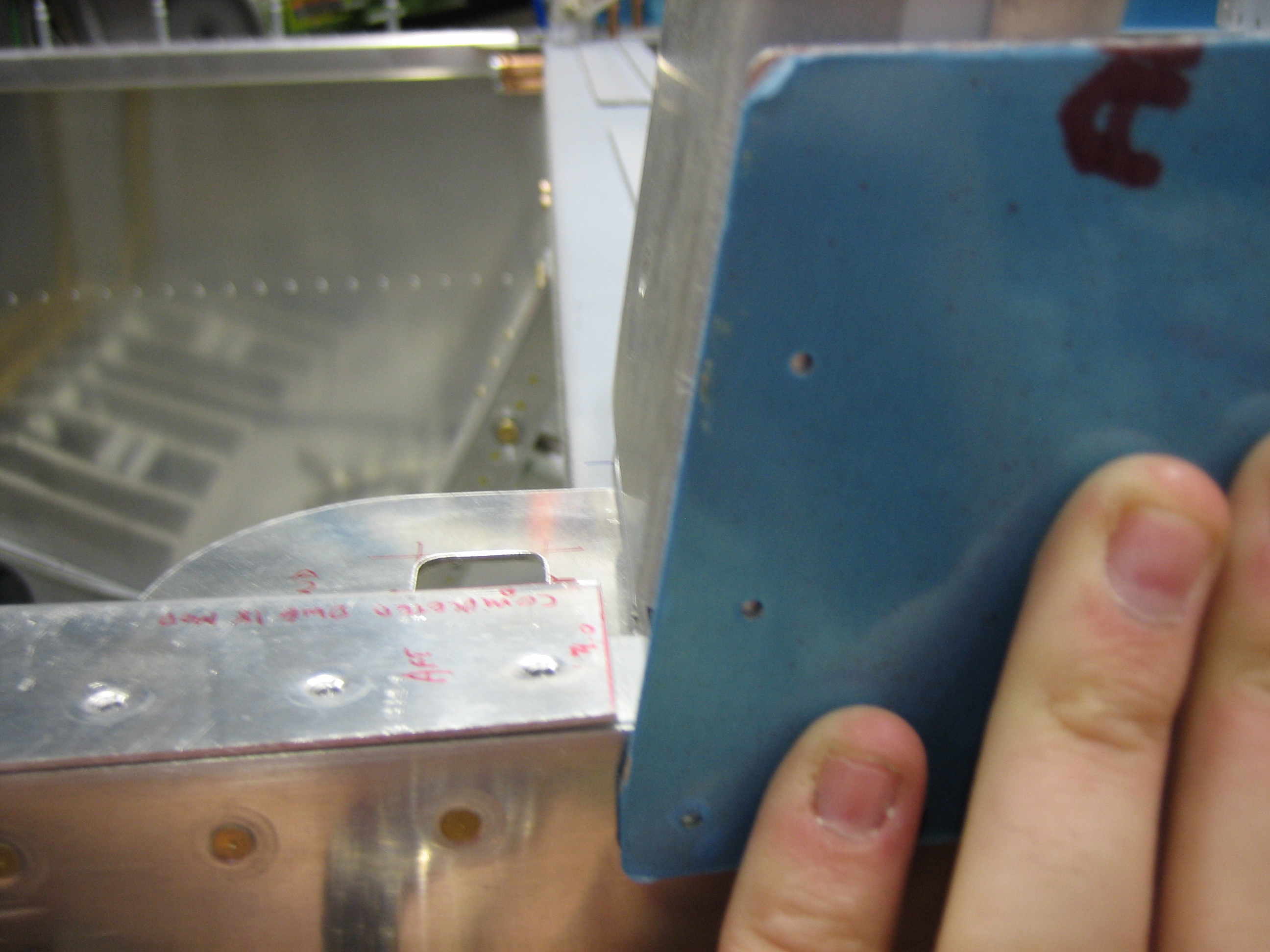
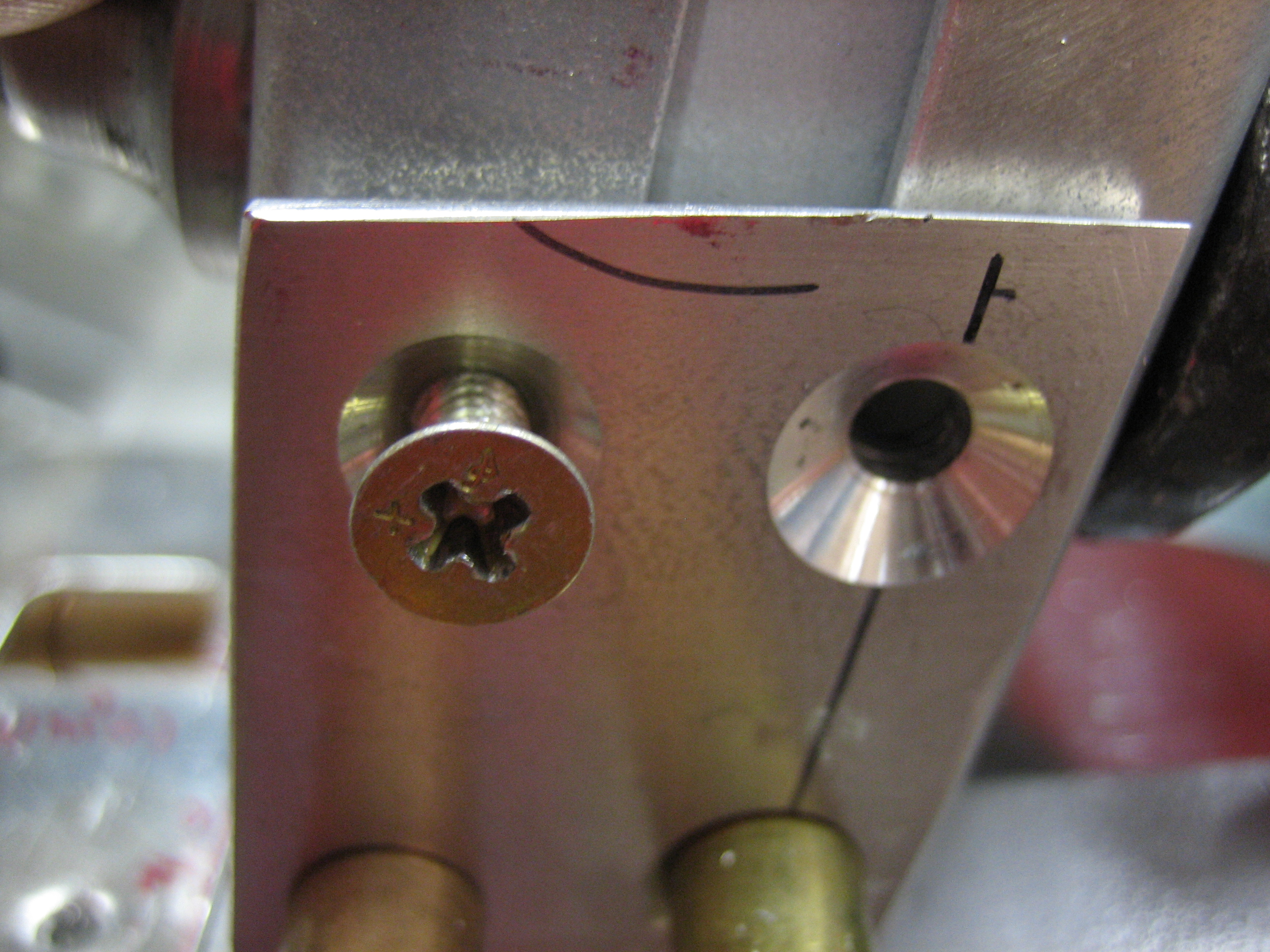
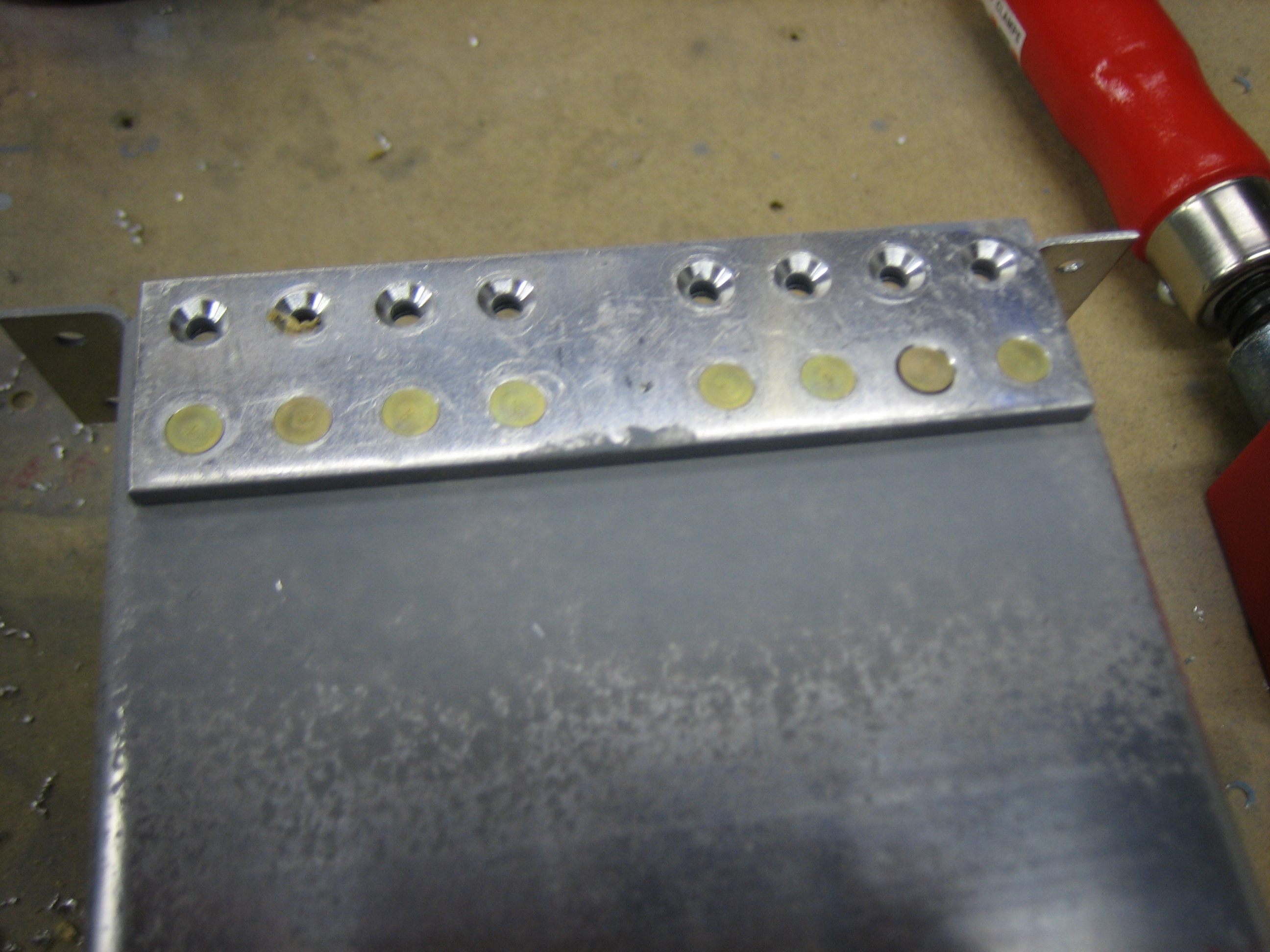
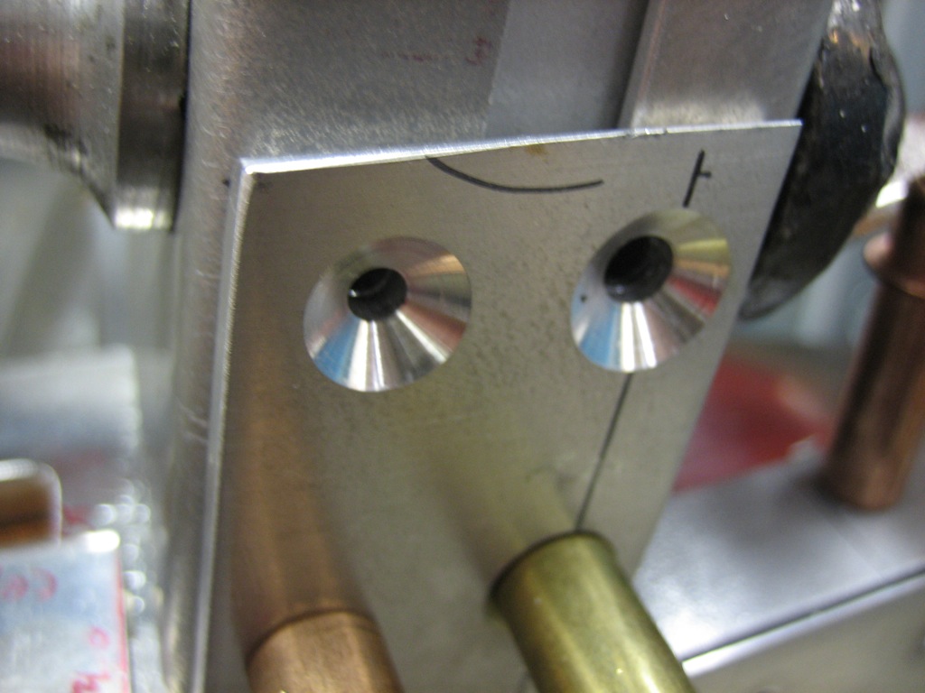
I then laid out and drilled the aft holes.  These are drilled perpendicular to the cabin frame and then countersunk for a #10 screw.  The countersink is asymmetric because the attach angle curves to follow the longeron.  The countersink needs to be deep enough so that the screw is below the surface of the attach angle since the skin lays over the top of this screw.

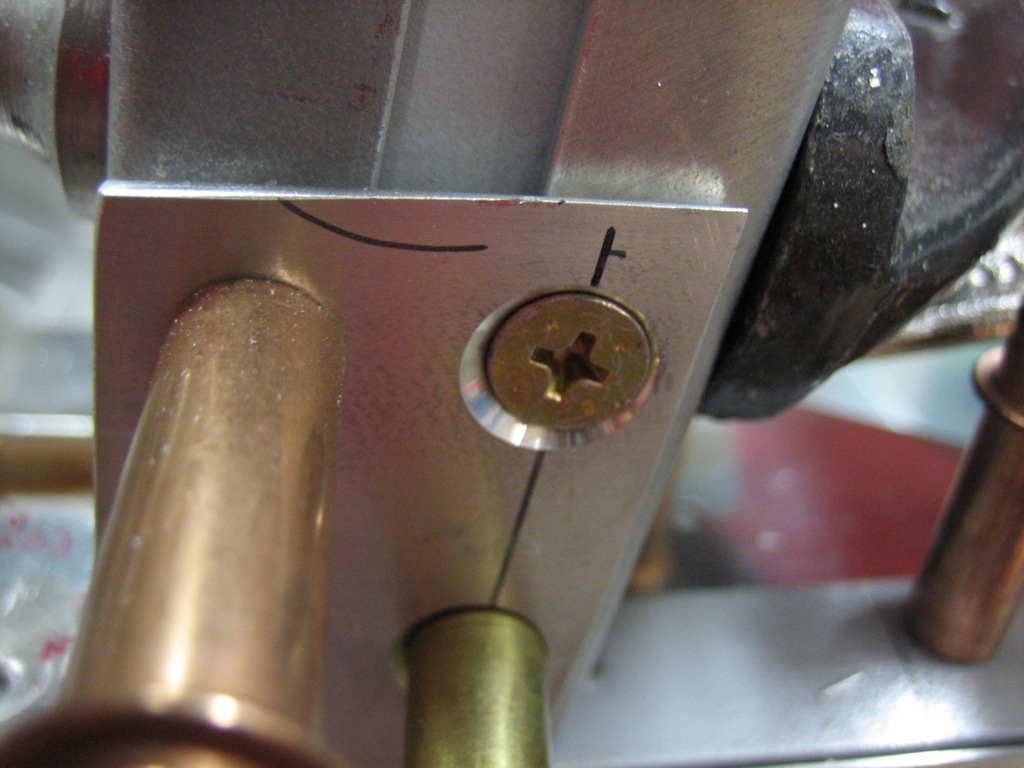
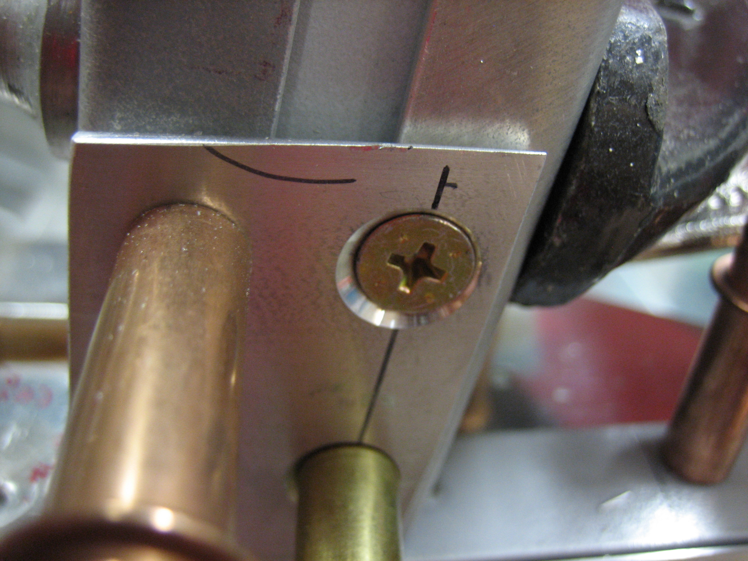
The forward holes are then countersunk for a #8 dimple.  Notice that these holes are drilled perpendicular to the face of the attach angle, not perpendicular to the cabin frame.  This is because a screw will screw in here and it needs to be flush with the skin.  The aft holes need to be perpendicular to the cabin frame because there will be a nut installed on the inside and it needs to be flush with the inside face of the cabin frame.

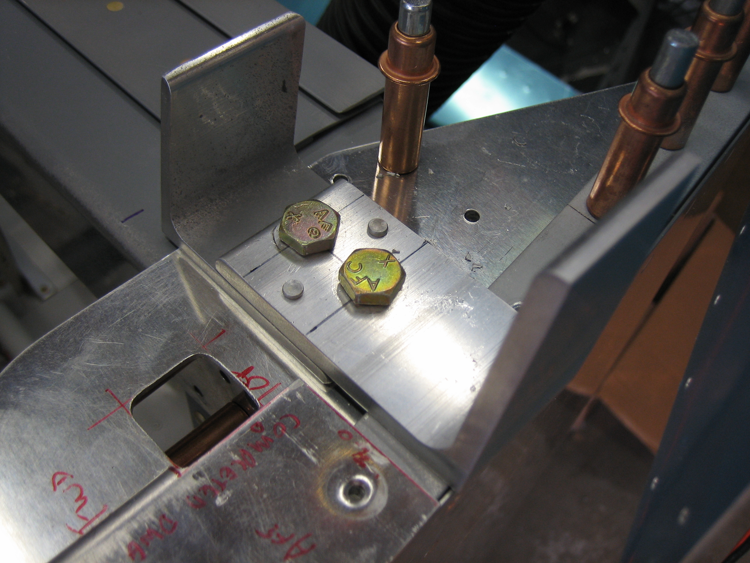
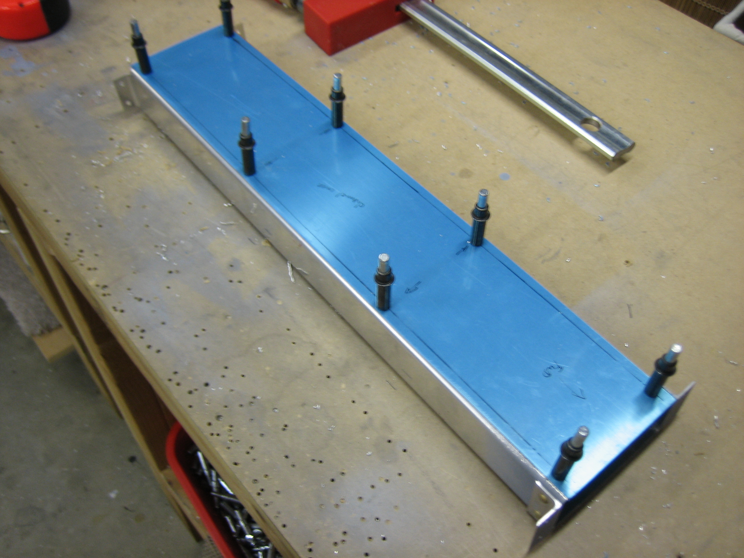
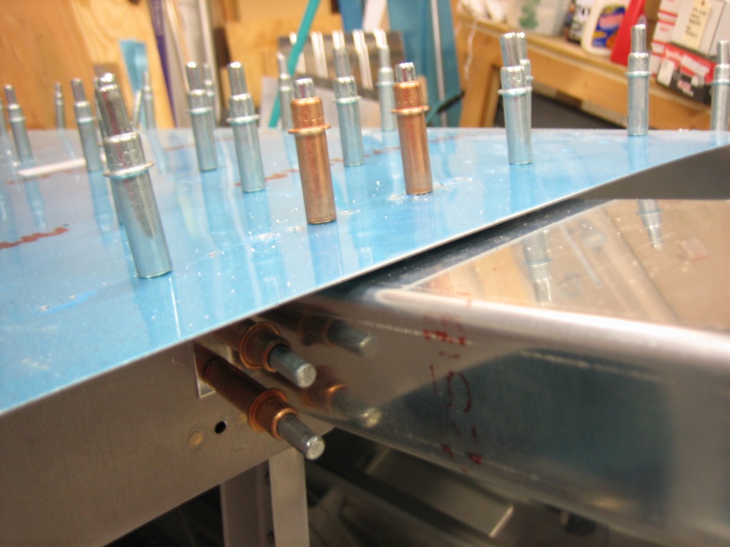
After countersinking the forward holes, I opened them up to #29 and then tapped them with an 8-32 tap for a #8 screw.

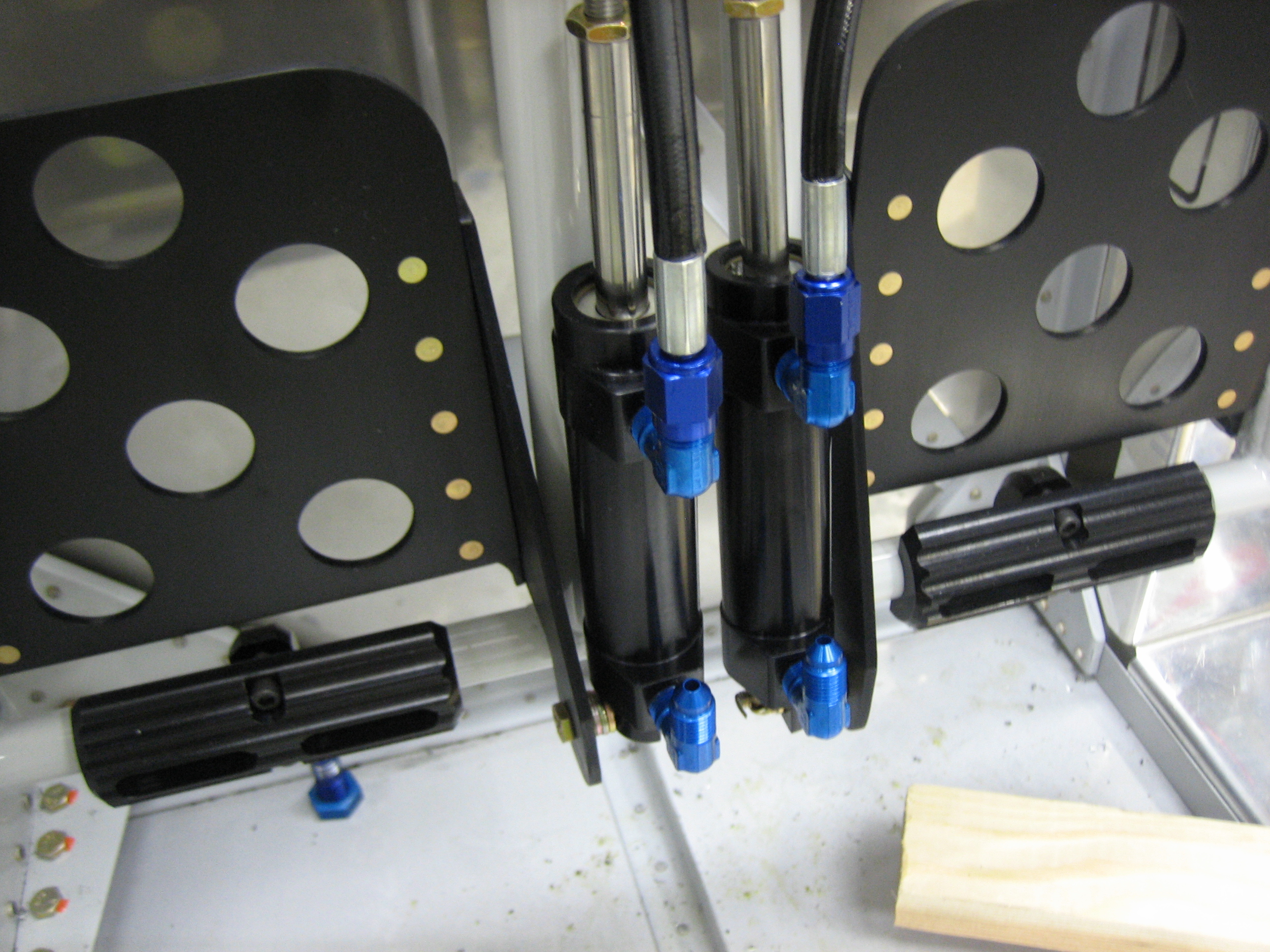
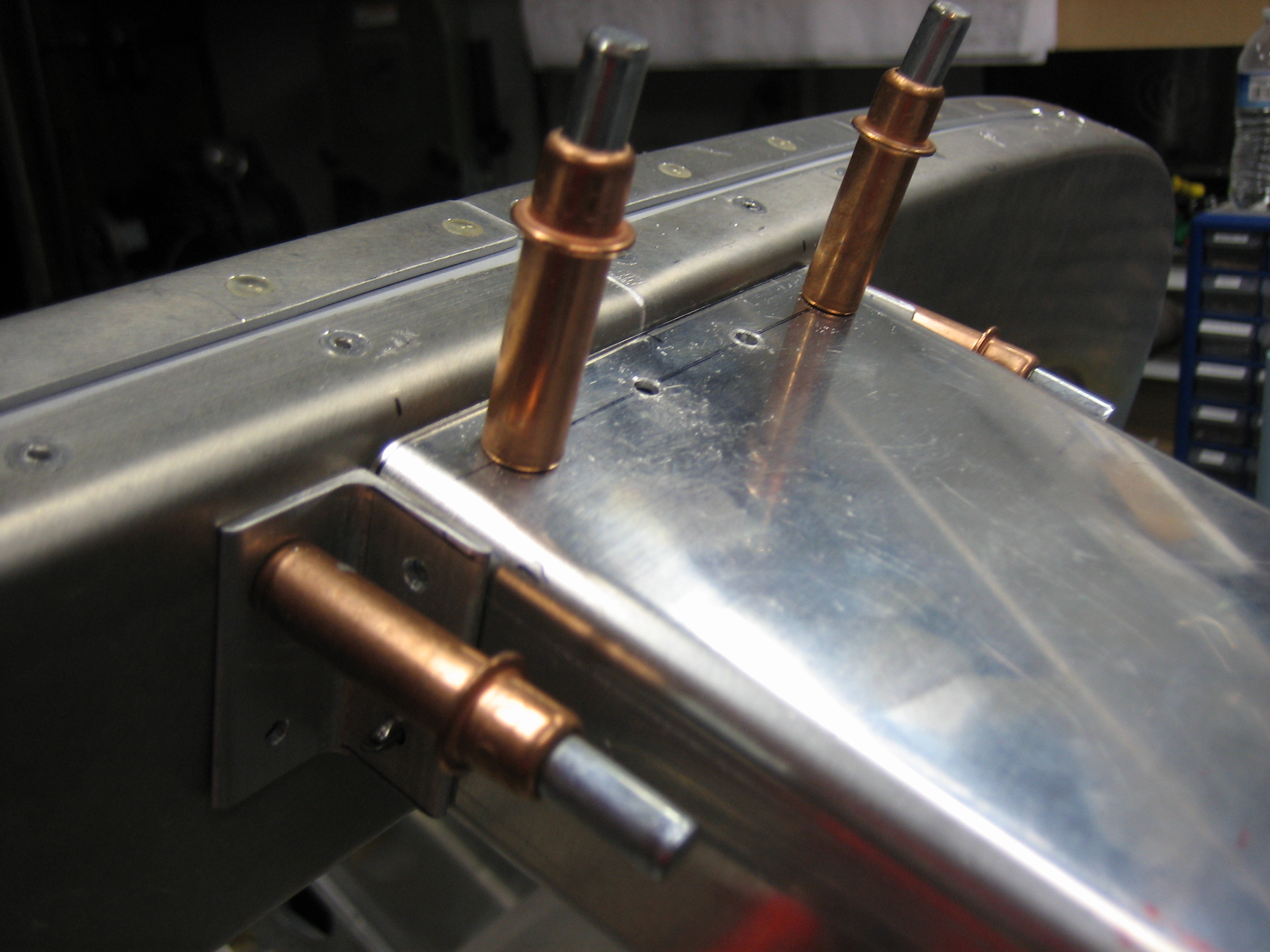
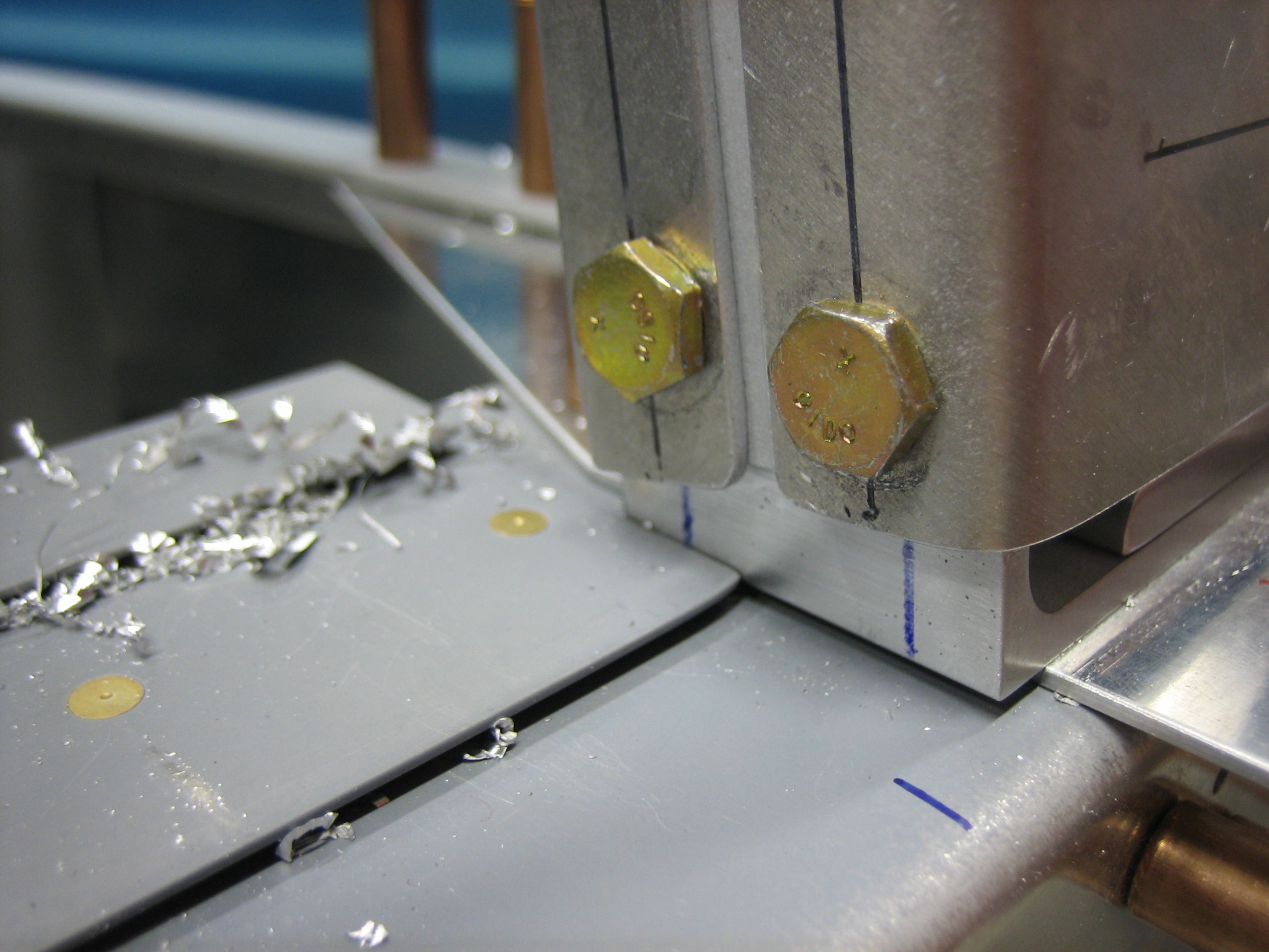
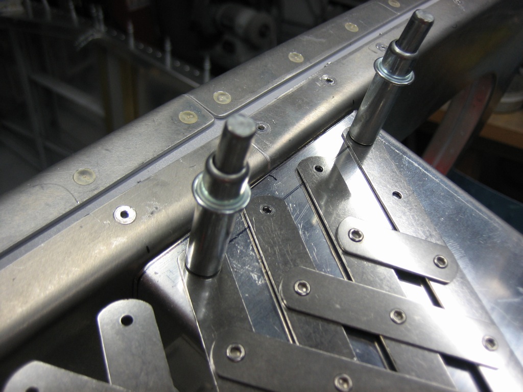
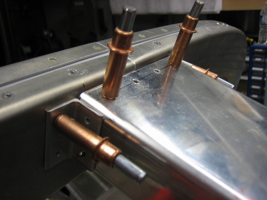
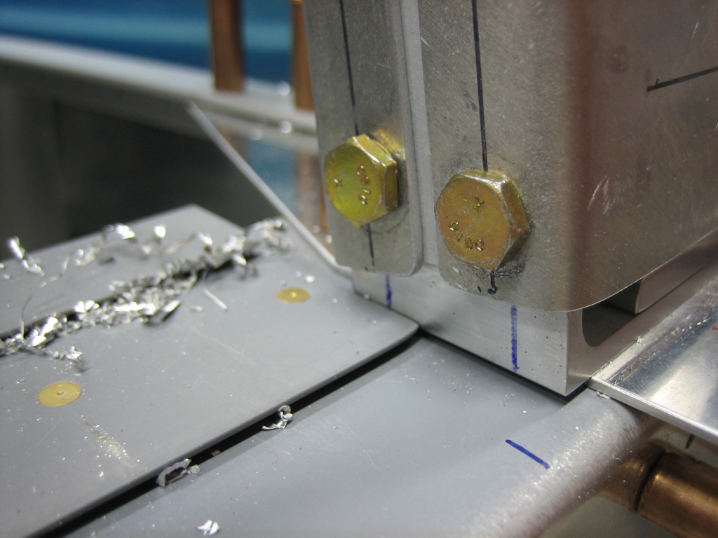
Finally, I drilled the inner holes for AN3 bolts and installed some scrap AN3-5 bolts.

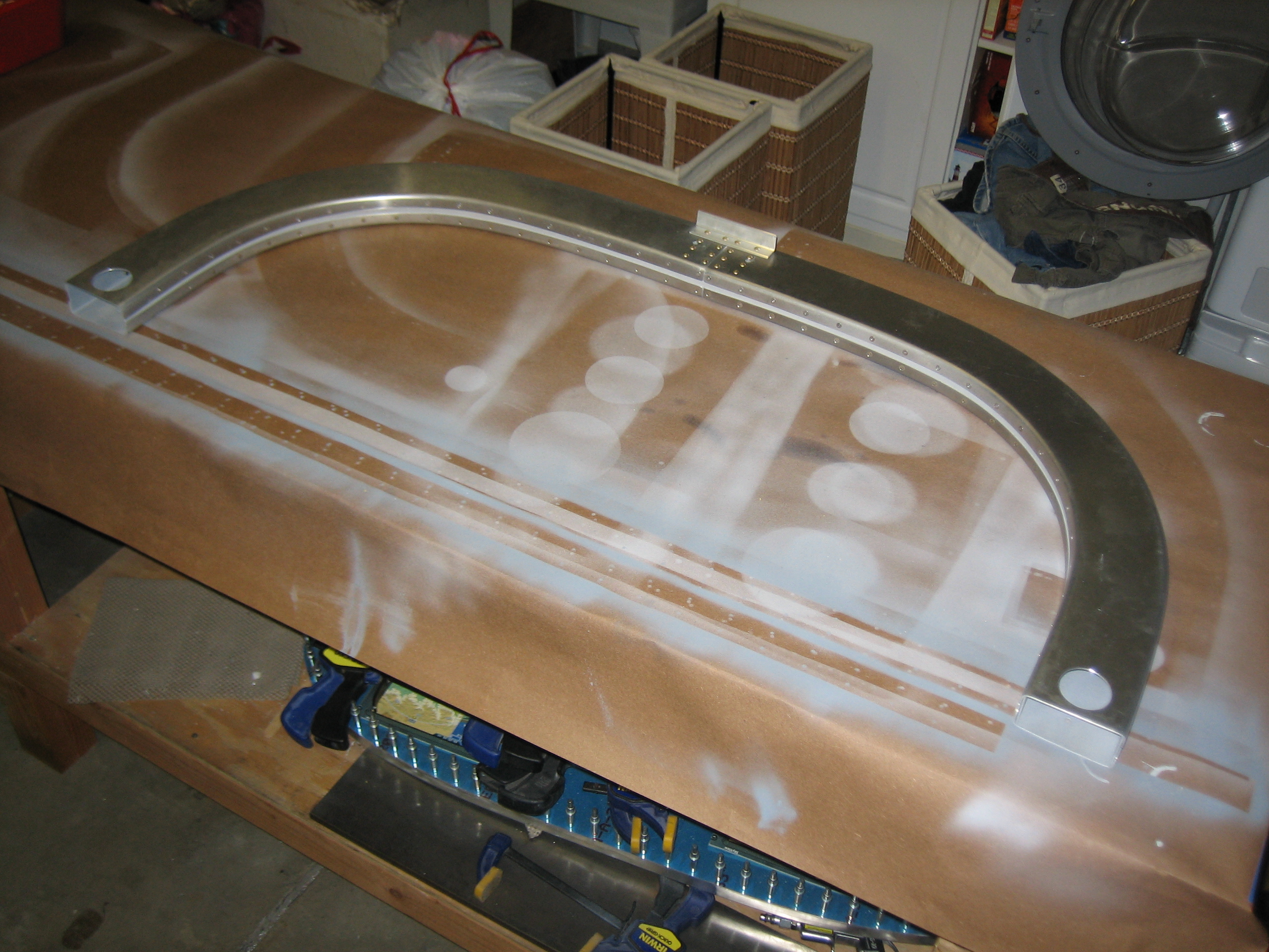
Here’s the whole cabin frame with all attachment points complete.

Worked on Cabin Frame Channel

I primed the mating surfaces and riveted on the forward cabin frame channel attach angles.

I also countersunk the doubler and riveted it onto the channel using the forward holes.  The aft holes will tie these pieces to the top skin and F-706 bulkhead.

I cut out the cover that I’m fabricating for the channel and drilled a series of holes with a #19 bit for #8 screws.

I riveted on some countersunk nutplates and screwed the channel cover on.  Here it is reinstalled in the plane.  I’m going to install a light here that can be used to illuminate the interior both in flight as well as during loading/unloading.

Toured NASA Dryden Flight Research Center and Edwards Air Force Base

I haven’t had a chance to work on the RV over the past few days, and today was no different, but at least I have a good excuse.  I woke up quite early and flew our Cardinal down to Mojave, CA with a couple of friends.  We arrived about 9 am and parked out in front of the Scaled Composites hangar.  White Knight Two was out on the ramp when we arrived.  The coordinator for our trip had arranged for a fleet of limos to drive us over to Edwards AFB, so we hopped in for the 20 minute drive over.  We boarded what looked like a retired prison transport bus for the last part of the trip.

First stop was the NASA Dryden Flight Research Center.  They have a nice museum with many of the supersonic and hypersonic aircraft on display as well as a number of other research aircraft.  We got to tour the flightline and saw the apparatus that loads the space shuttle onto the back of the 747 for the trip to Florida when the shuttle lands at Edwards.

After lunch, we went to Edwards where we toured the base and then toured the flight line.  They have an enormous number of aircraft there that they use for a wide variety of flight tests.  We saw a huge number of F-16 and T-38 aircraft that they use for chase and flight currency.  They also have a number of KC-135 and C-17 aircraft stationed there.  We saw a B-1B on the flightline as well as a couple of F-22s and one F-35 Joint Strike Fighter.  There are a number of other aircraft based there including the Predator, but we didn’t get to see them.

The dry lake bed is pretty amazing.  40 square miles of basically perfectly flat surface that’s harder than concrete.  They’ve painted 18 runways out on the lake bed including one that’s 7 miles long.  There’s also the world’s largest compass rose painted on the lake bed that is 1 mile in diameter.

Started Canopy Hinge

I started working on the canopy hinge mechanism tonight.  First up is to rivet the outer subpanels to the forward ribs using the top two holes with flush rivets on the inside.  This is so the hinge blocks can be mounted flush to the ribs.

I clamped a piece of scrap metal over the small inner riblets to align it with the outer forward ribs.