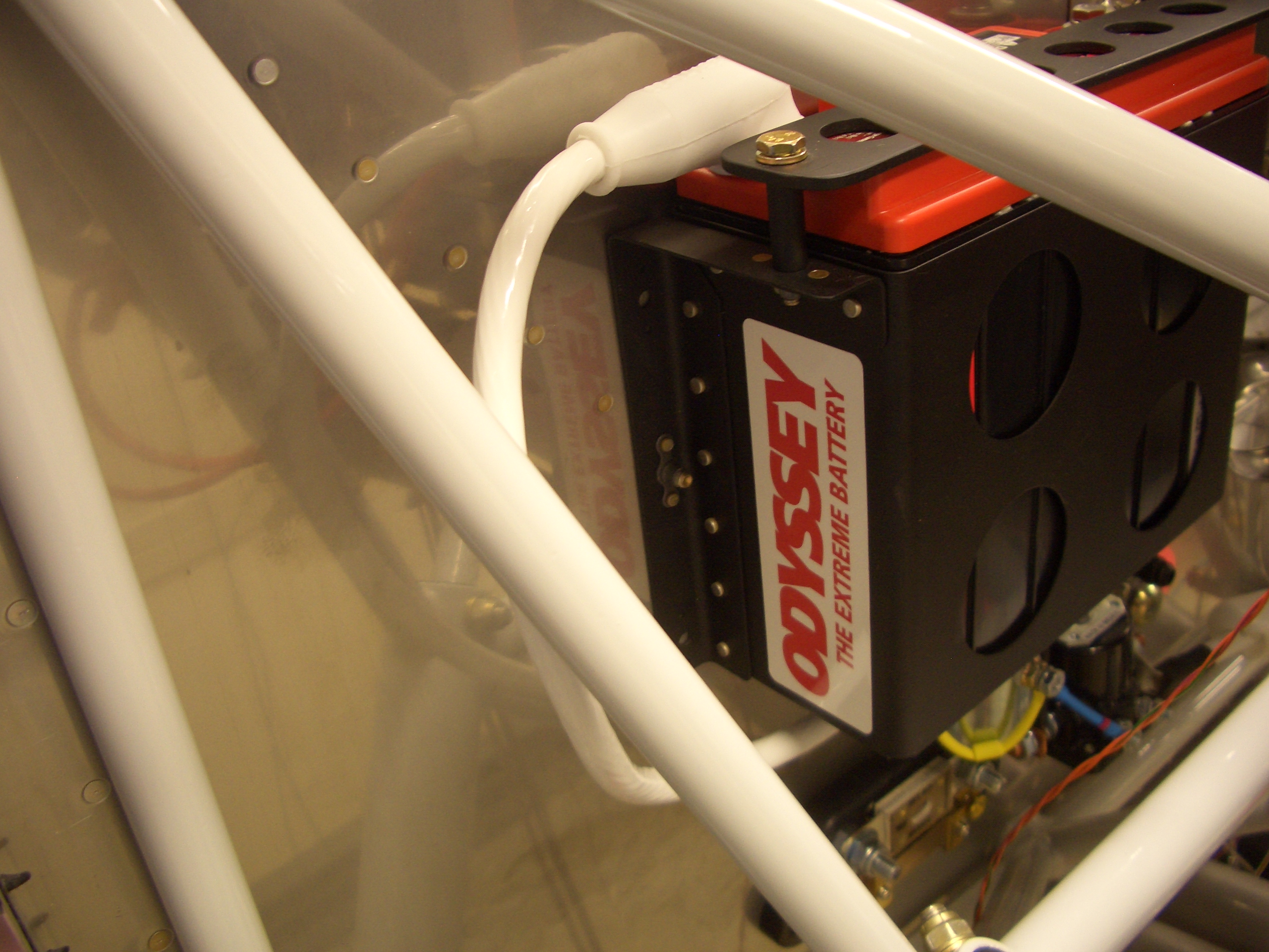
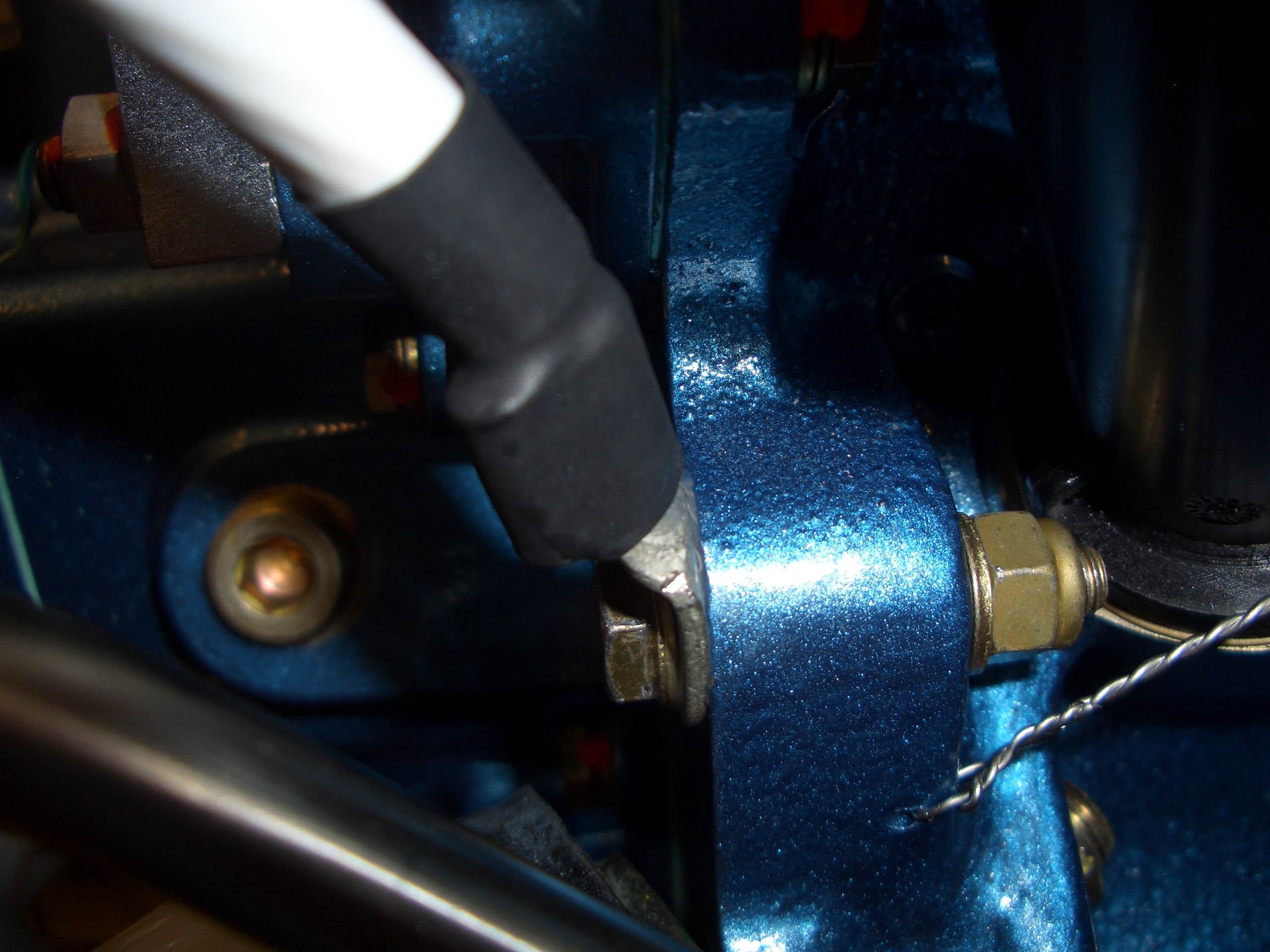
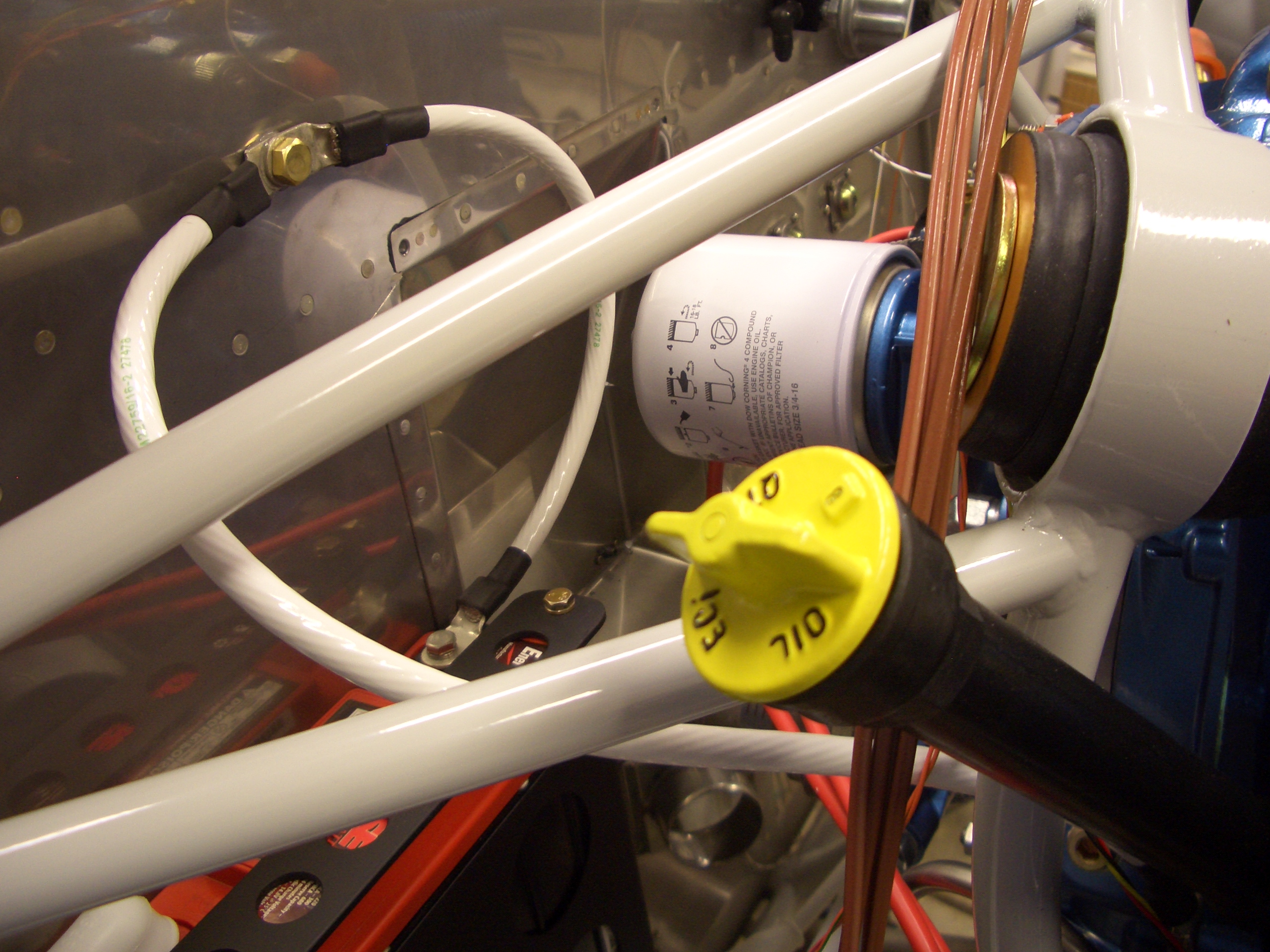
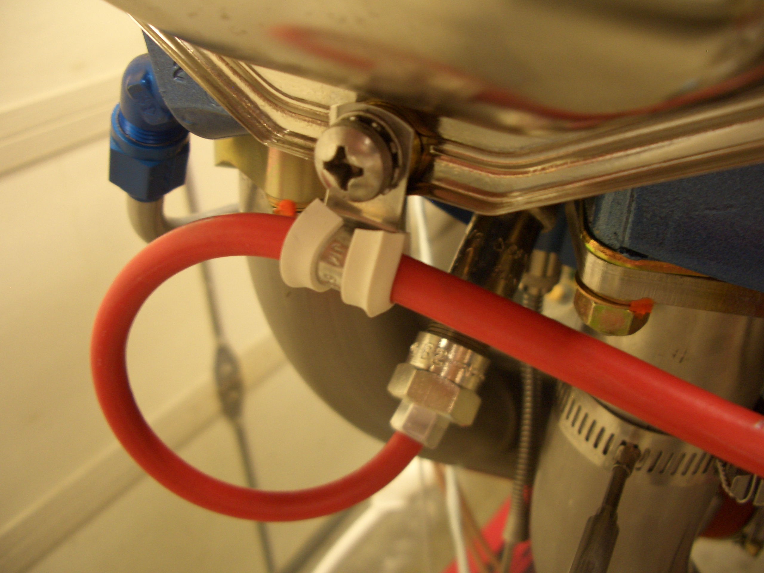
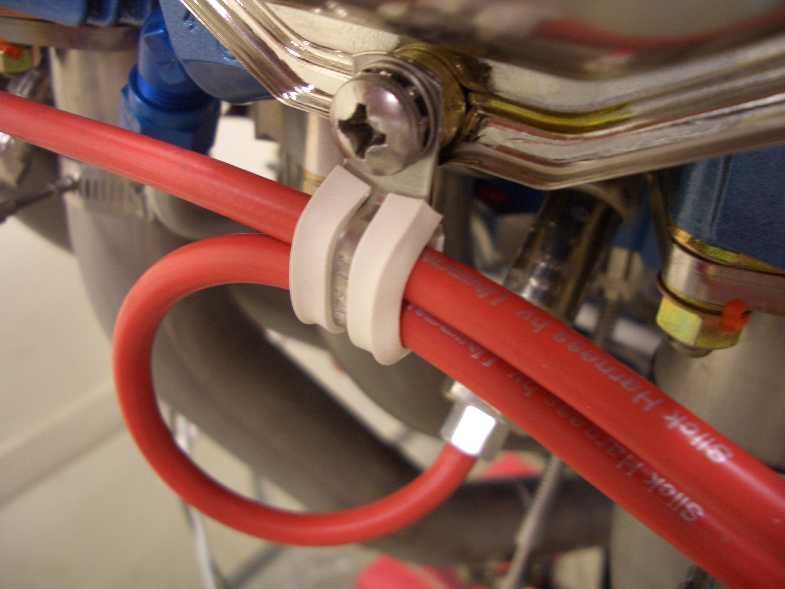
I finished the battery positive cable. There will be a couple of adel clamps securing this to the adjacent engine mount tube to prevent the terminals from carrying the full weight of the cable.
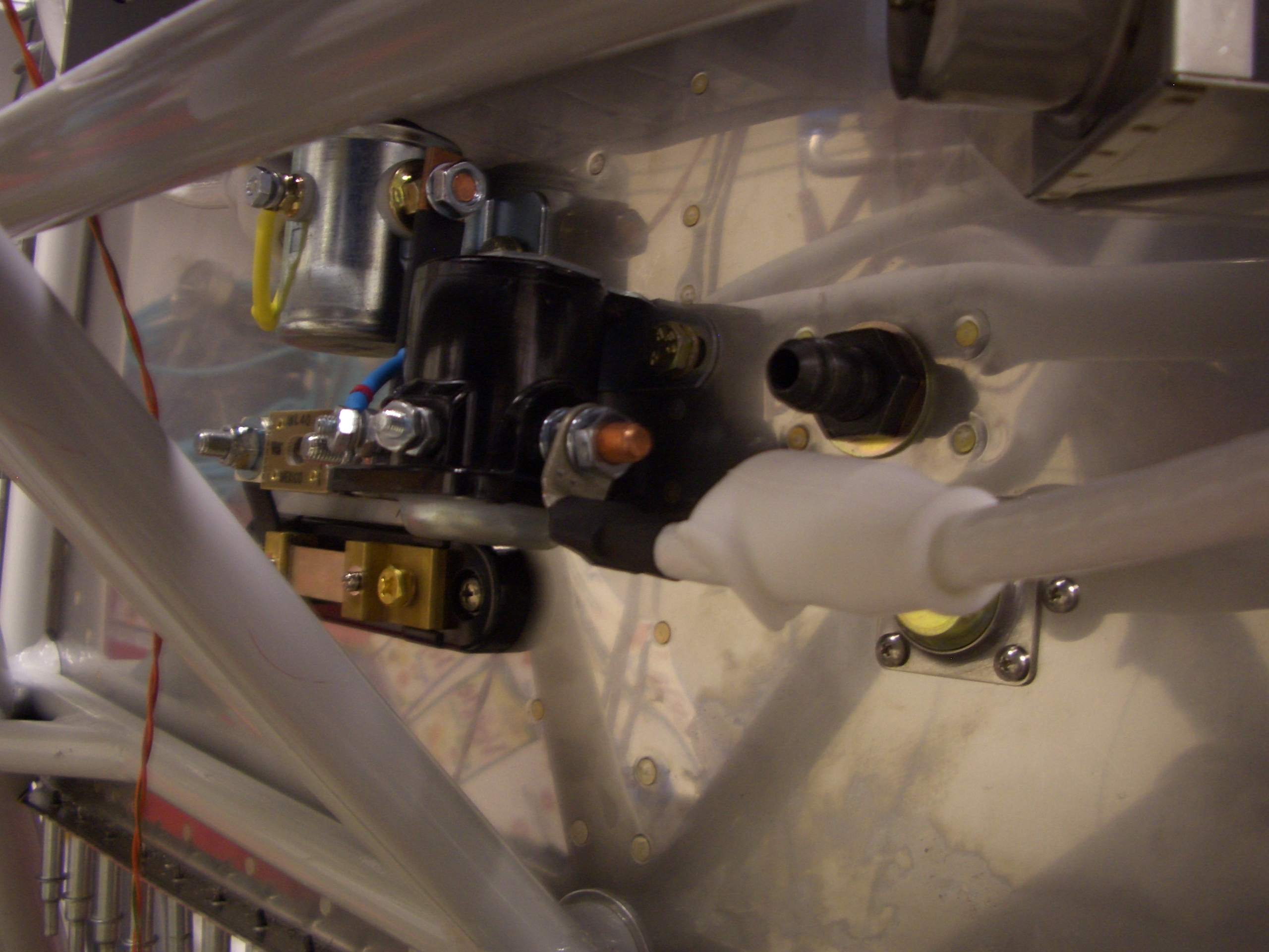


I finished the battery positive cable. There will be a couple of adel clamps securing this to the adjacent engine mount tube to prevent the terminals from carrying the full weight of the cable.
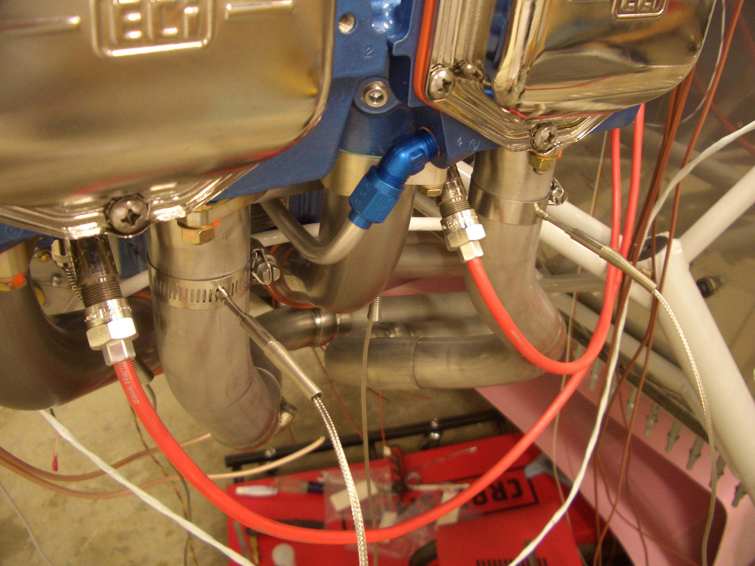
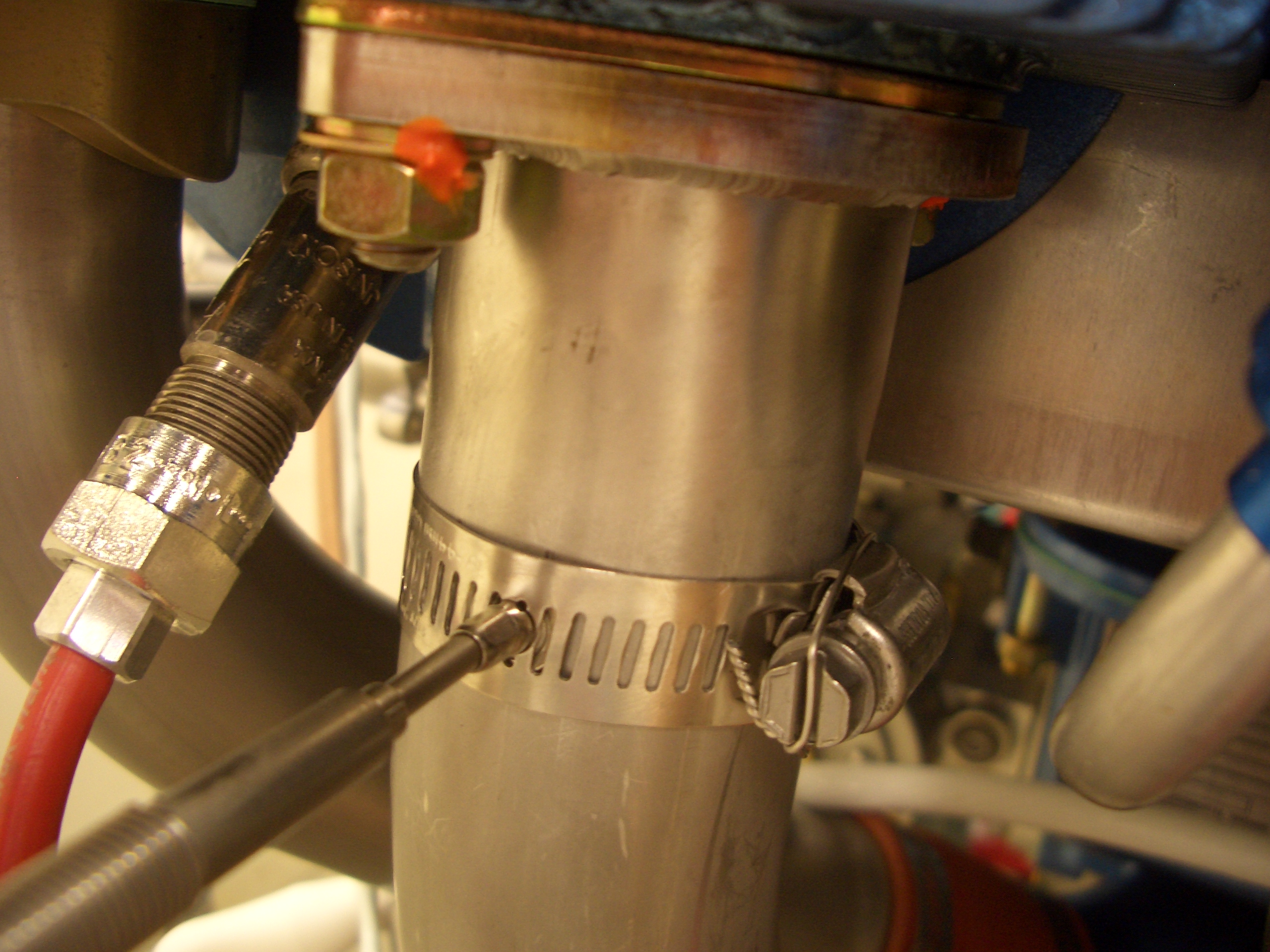
I installed my EGT probes tonight. Dynon recommends 2-8″ from the exhaust flange. The precise distance isn’t important, but it’s very important that the distances are the same for each cylinder since that lets you compare EGT readings across cylinders. Anything over 2″ on my exhaust setup would put the probes past the first bends, and it would be hard to remain accurate on the measurements. These constraints pretty much dictated that my EGT probes would be at exactly 2″ from the exhaust flange. I positioned the probes so that they stick straight out from the sides of the pipes. I’ve seen a lot of builders angle these one way or the other to try and keep them from sticking out so far, but there is plenty of clearance from the cowl sides and this keeps them from interfering with other things like the lower spark plugs.
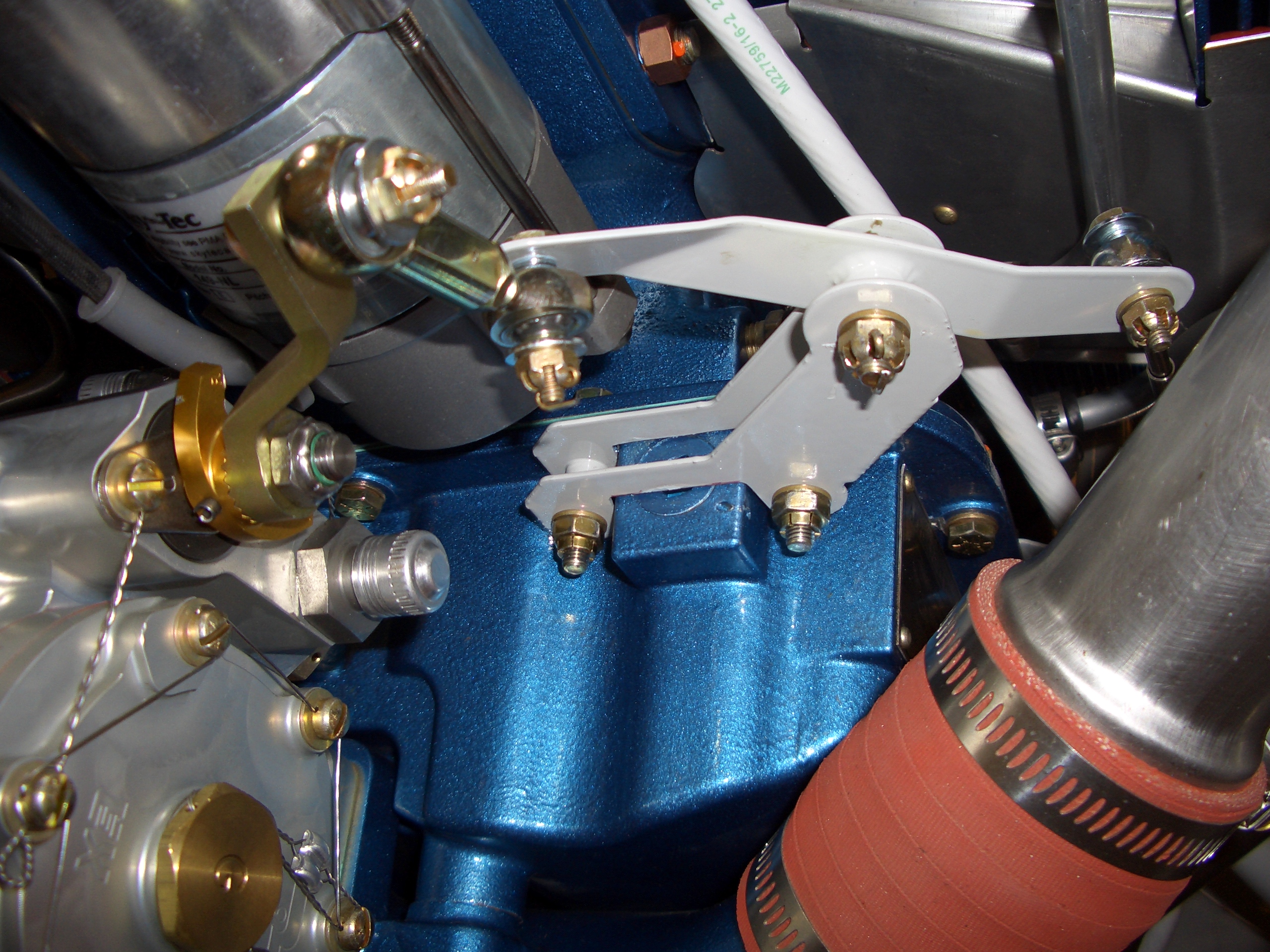
I received my AN932-5D plug from General Aircraft Hardware. $17 bucks shipped was kind of a ripoff, but the alternatives would have been even more expensive. I had to grind off about 3/64″ from the visible face here to get the surface flush with the sump. After installing it, I used the touch-up paint that came with my engine to paint the exposed aluminum face to match the engine. I then installed the mixture bellcrank to the sump.

I also regreased the pivot point and installed the cotter pins in the pivot bolt and the output bearing bolt. The other end of the output shaft is still loose until I get the replacement servo arm from Precision Airmotive.
I’m pretty swamped with our developer conference at work, so progress will be slow for the rest of the week, but I’m still trying to get a few things done here and there.
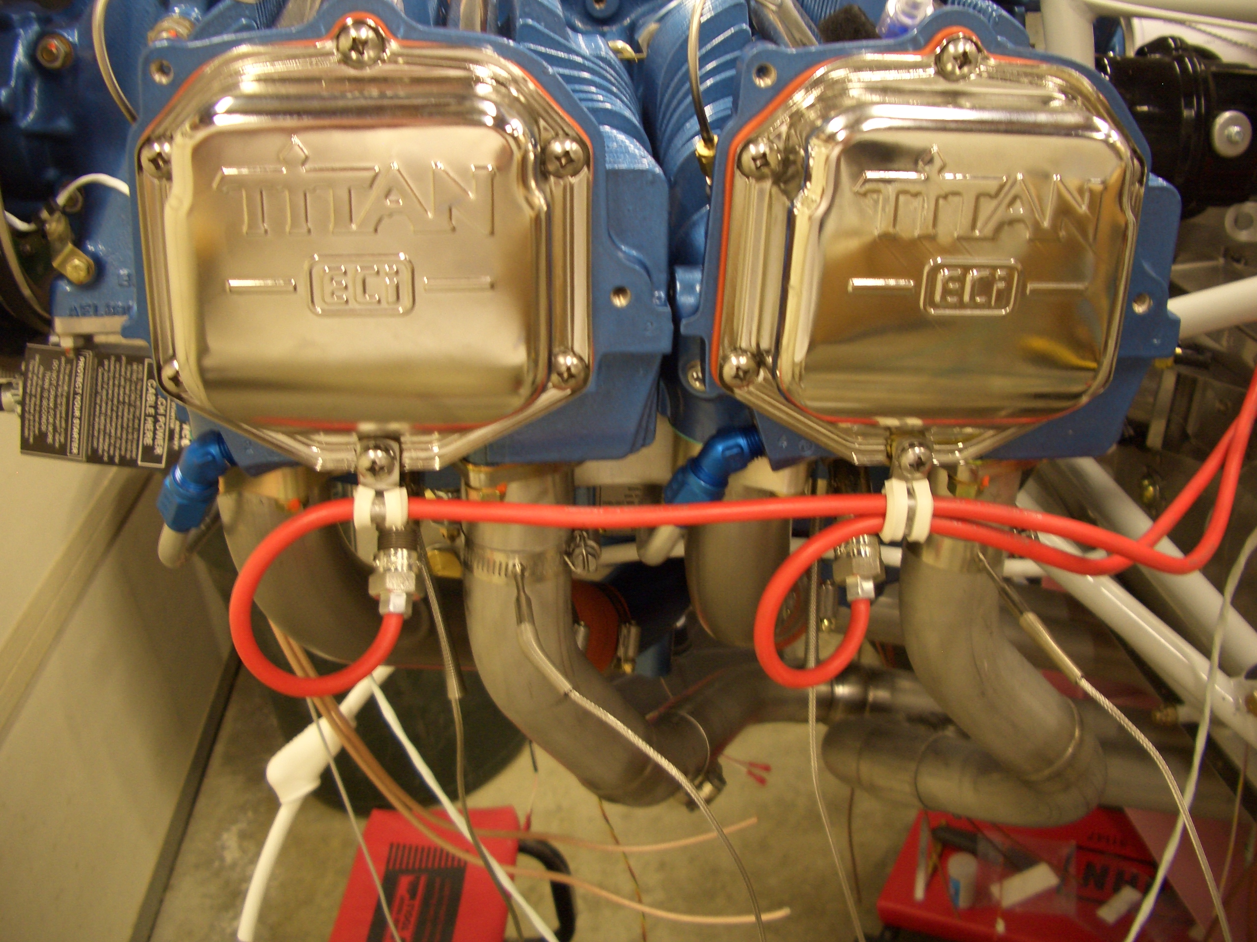
I ordered some one and two wire spark plug wire adel clamps from Sacramento Sky Ranch. The order came in today, so I installed some of them on the cylinders. These are stainless steel with silicone cushions that are good to 400ºF.
Our developer conference is finally over. It’s great fun, but a lot of work and incredibly exhausting. We launched the revolutionary new iPhone 4 which I worked on and I can’t wait to see how well it does in the market.
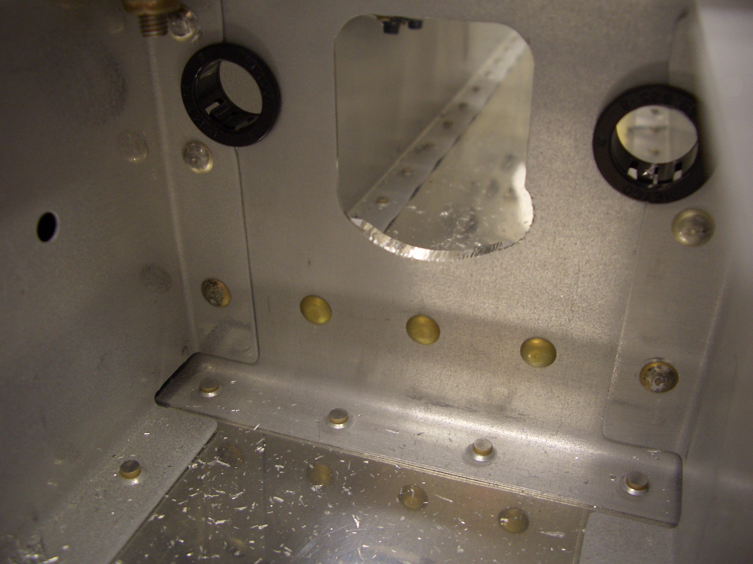
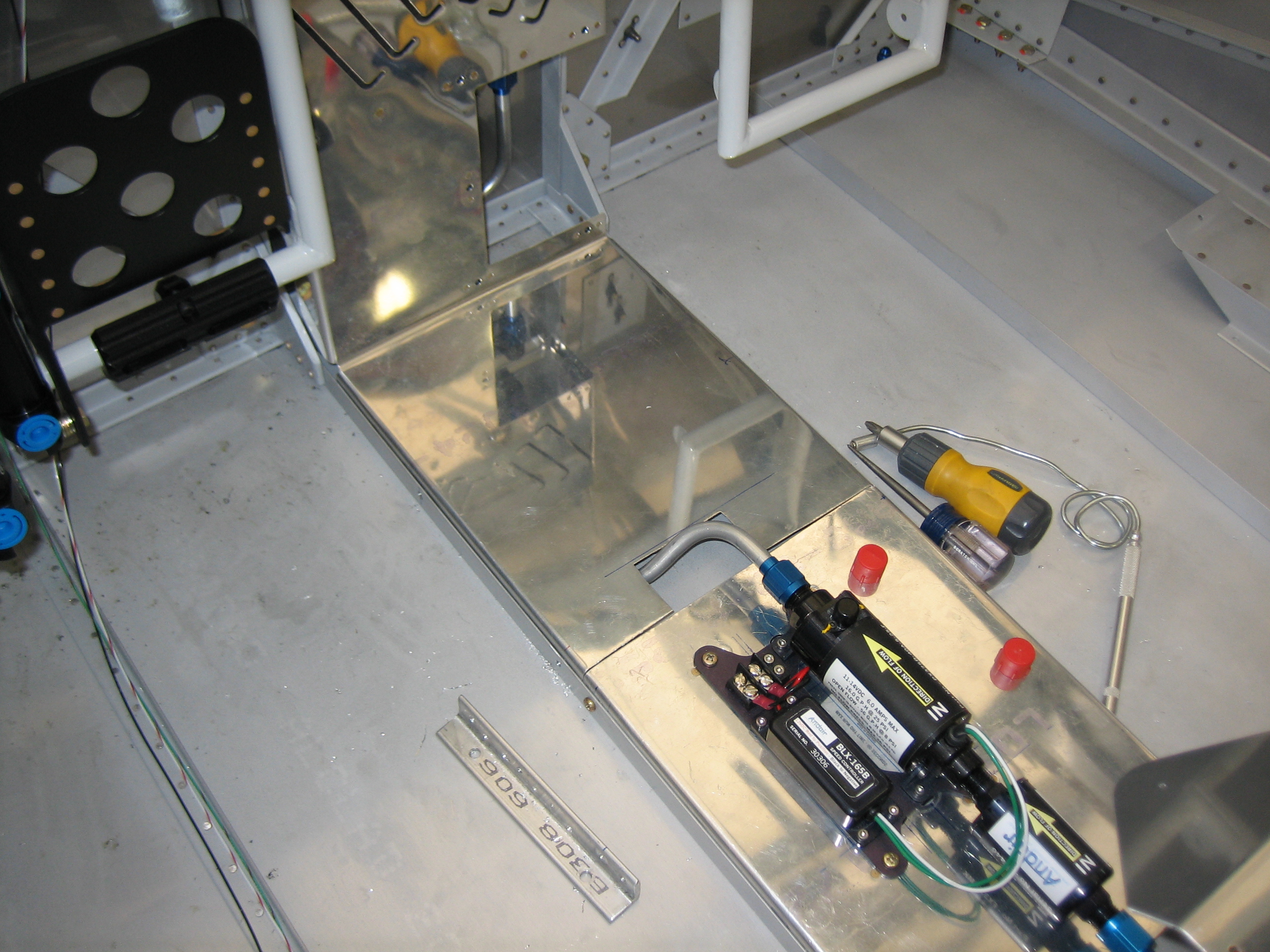
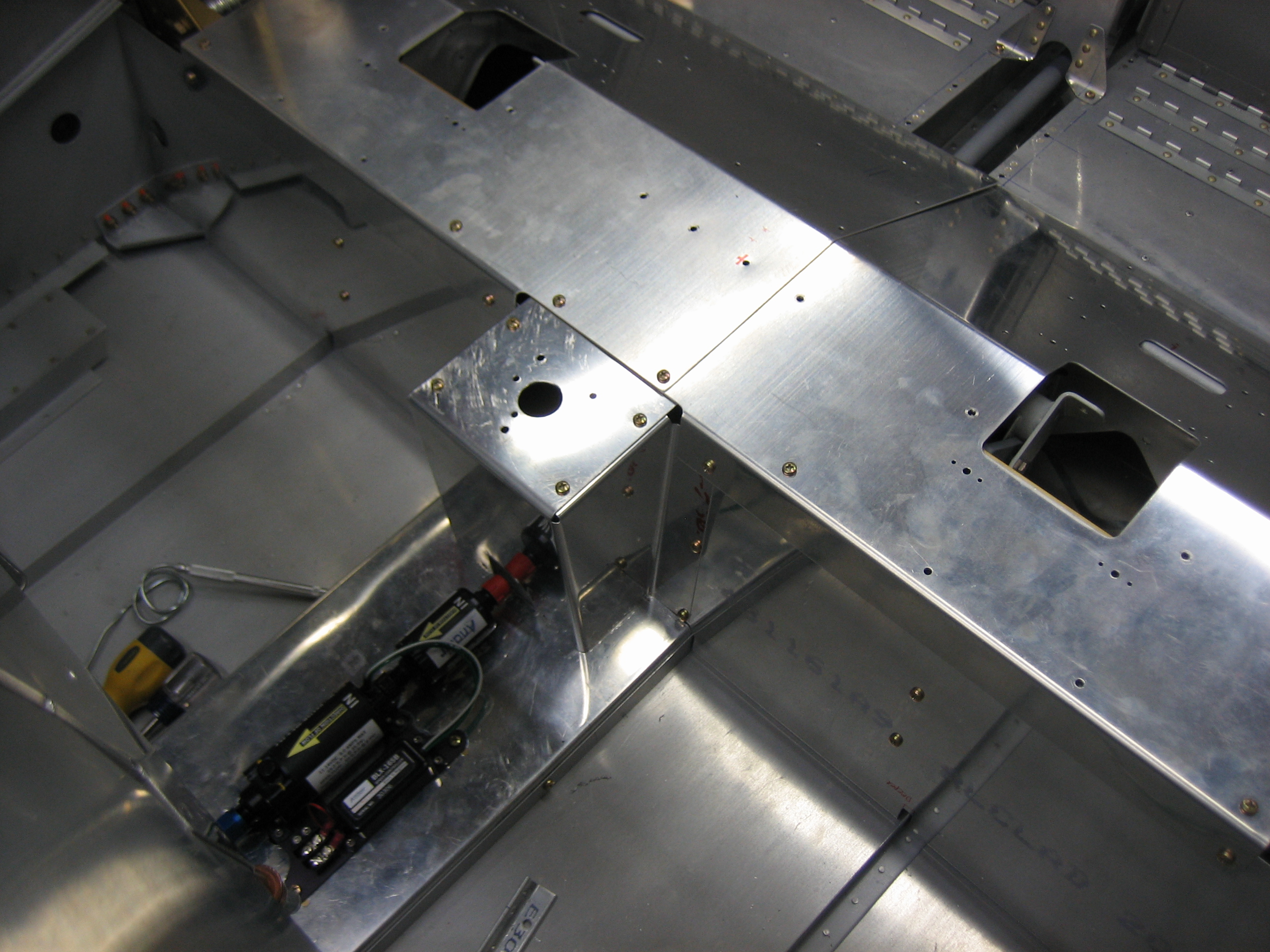
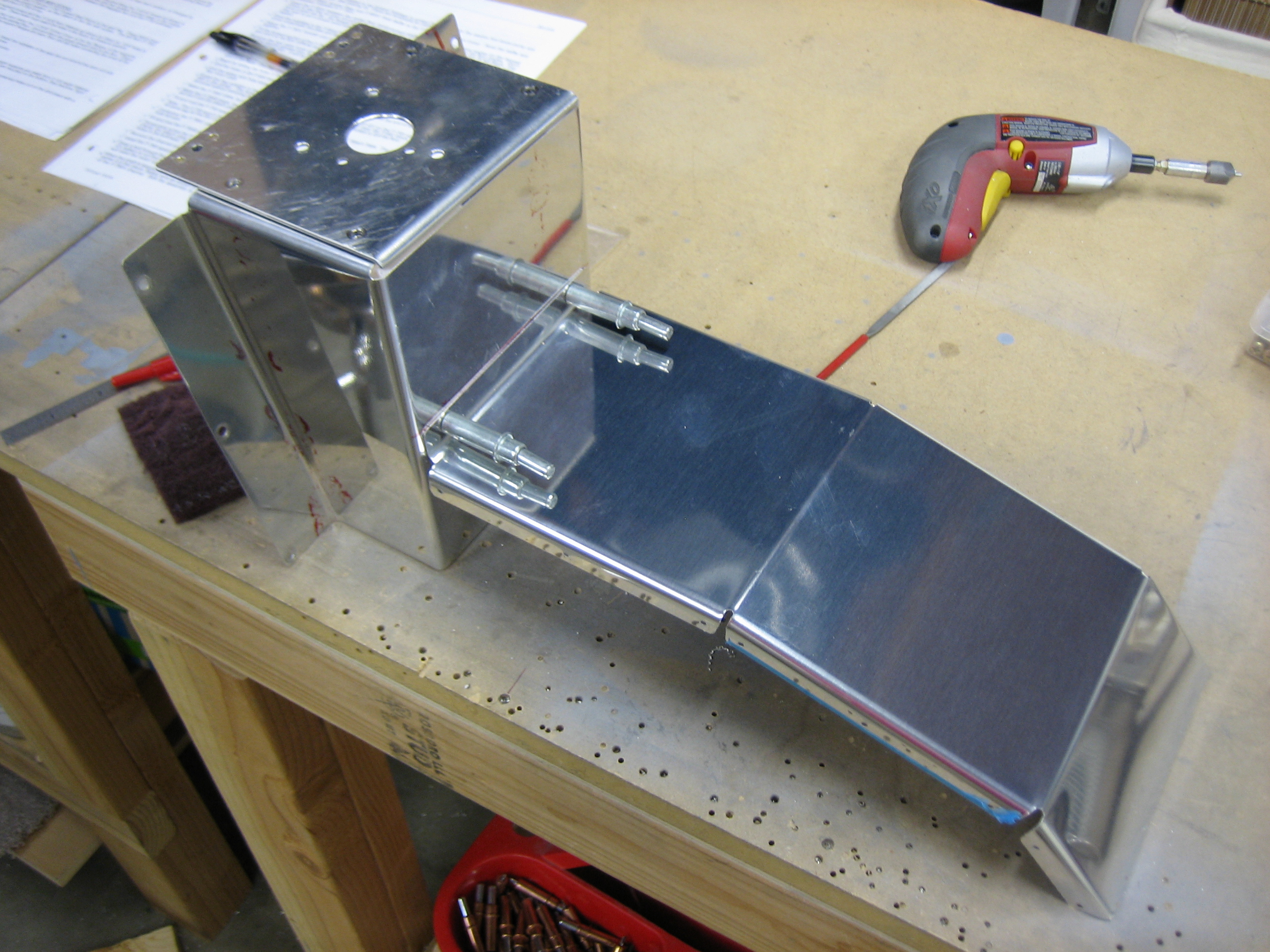
Anyway, I spent most of the day just taking it easy and hanging out with the family after not seeing much of them for the last week, but I did sneak out into the garage for a bit after everyone headed to bed. First, I cut the forward cover in two so that the forward part could be easily removed without having to touch the fuel pump or fuel lines. The aft part is still removable, but I hope that is almost never necessary. I’ll run conduit under here so that I can run additional wires without having to remove this.
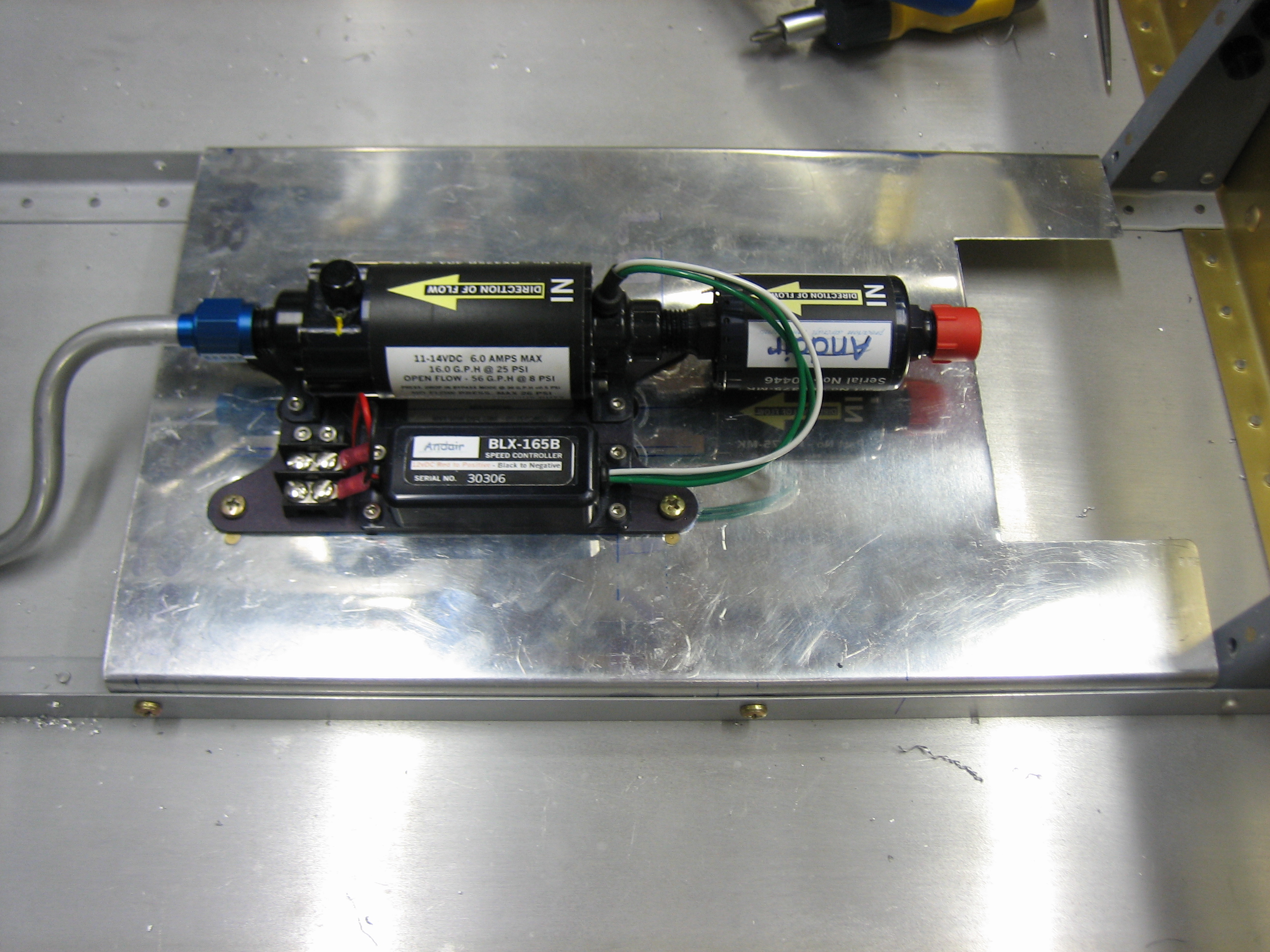
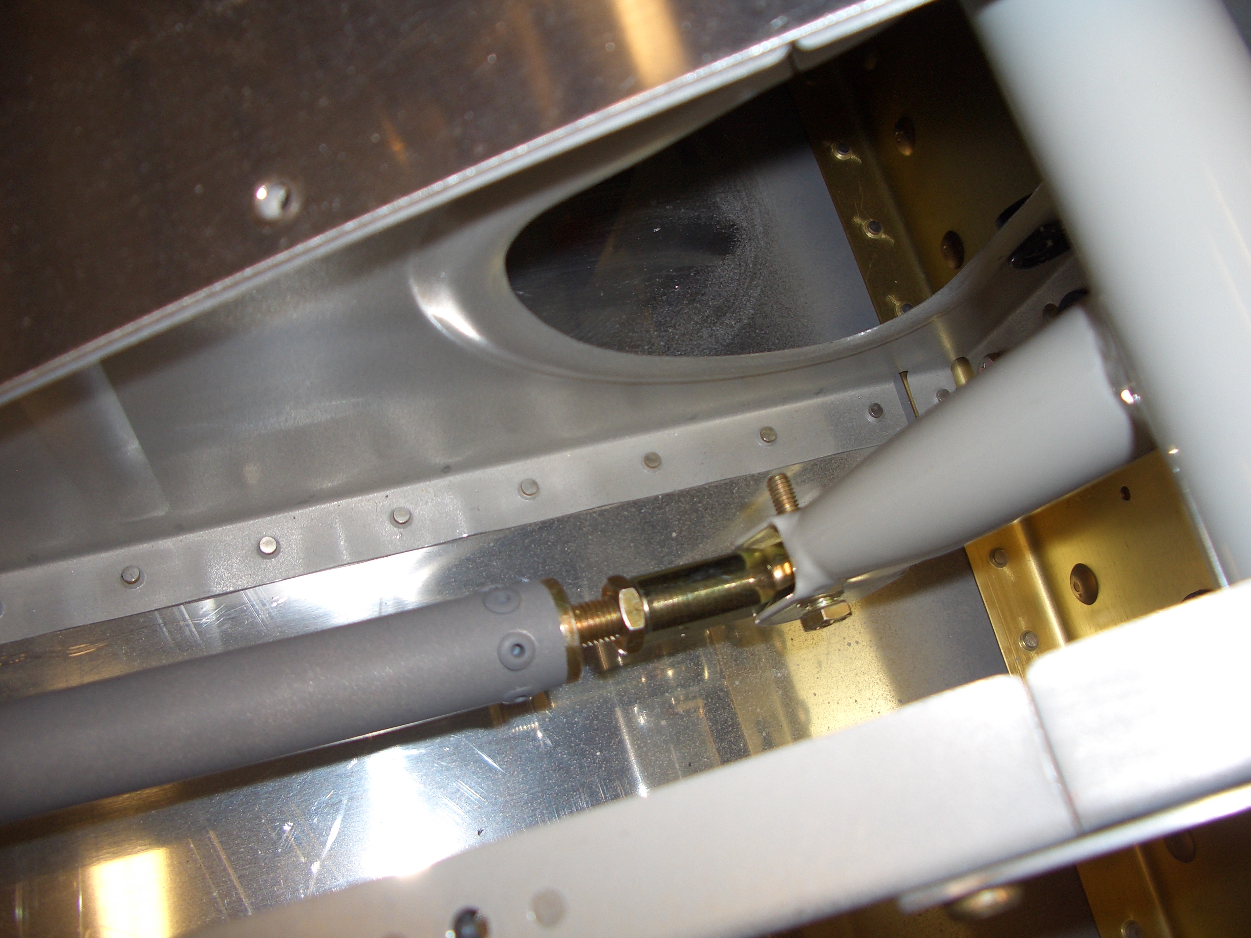
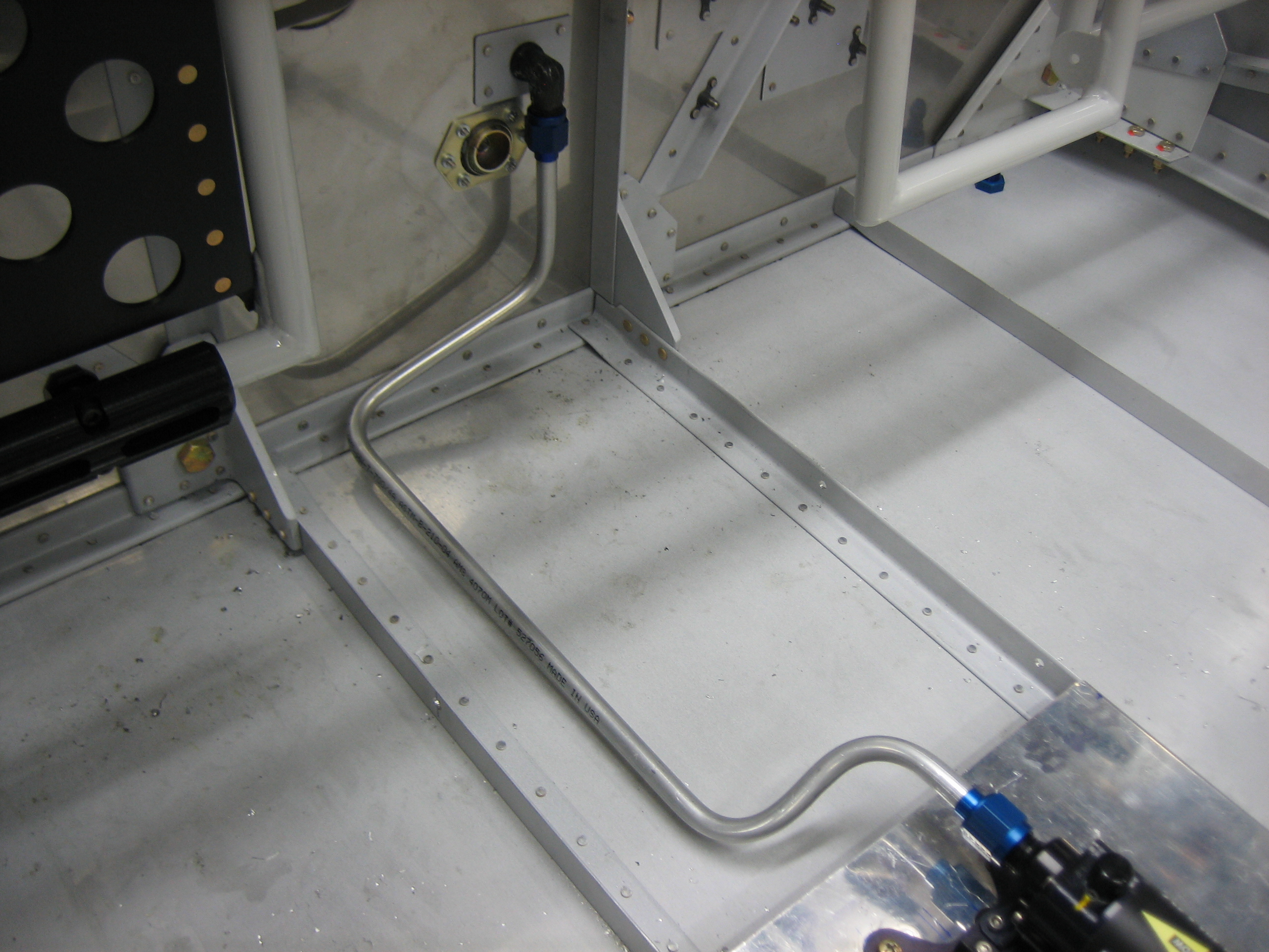
I also fabricated the fuel line from the pump to the firewall fitting. I held off on this for a long time because I was trying to decide whether to put the fuel flow sensor here or after the fuel servo. Most people seem to install it here, but claim that the fuel flow is incorrect when the electric fuel pump is on. Some have also claimed that there is a small risk that this location could result in vapor lock since the mechanical pump is pulling fuel through the sensor. The fuel flow sensor manufacturer recommends installing the sensor downstream of all pumps, and even downstream of the fuel servo for the most accurate readings. Because of this, I’ve decided to install the sensor just after the fuel servo, probably just under cylinder 1. With this decision made, I could go ahead and fabricate this fuel line. One additional benefit I hadn’t really thought of is that this reduces the number of fuel fittings in the cockpit which theoretically reduces the risk of an in-cockpit fuel leak.
I ran the line on the left side of the bay since a large bundle of wires from the panel will enter this area just to the right of the firewall fitting and snake down under the forward cover and then under the aft cover. Keeping the line to the left gives me a little more room to run these wires.
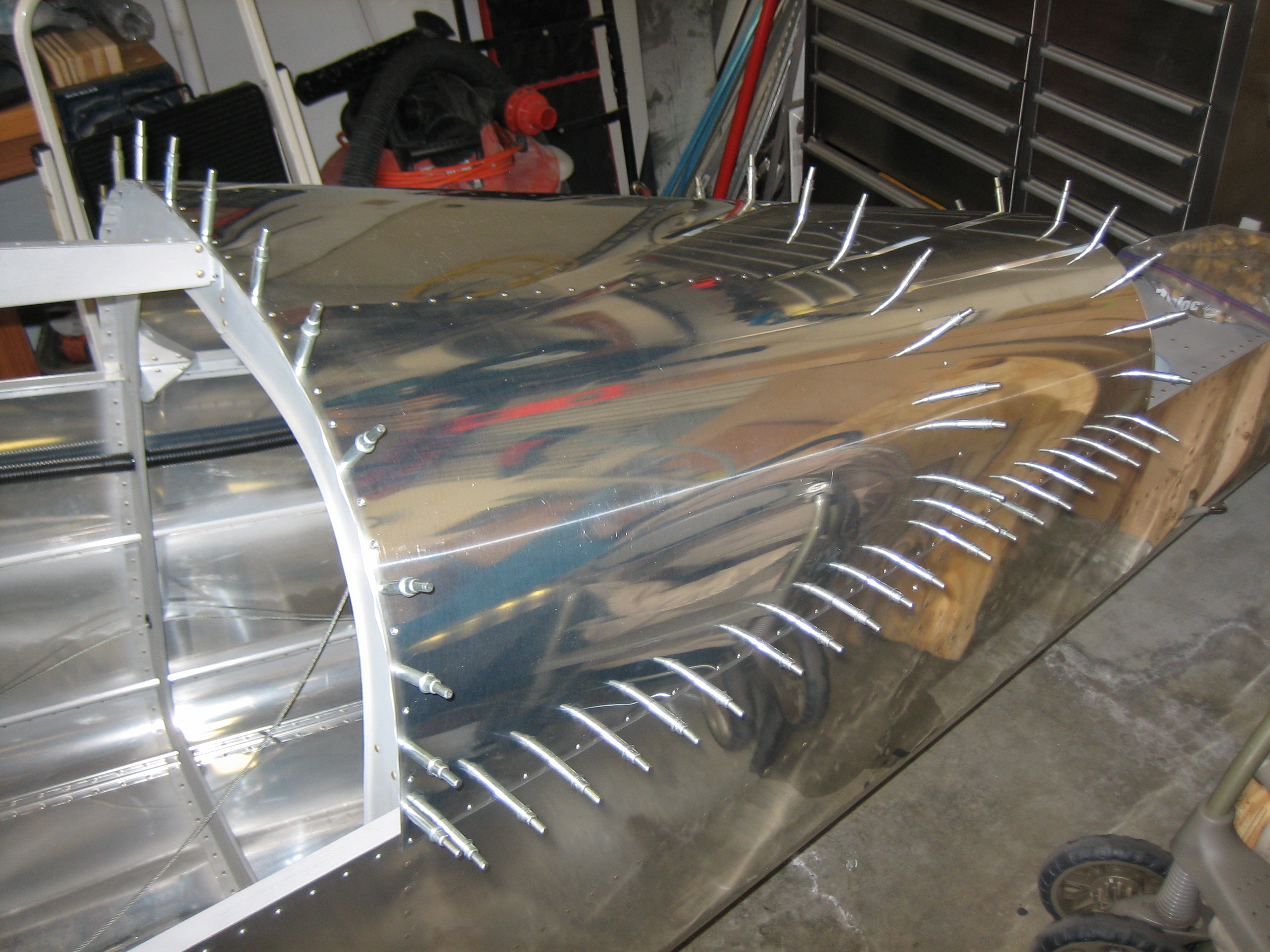
My buddy Andre stopped by today and prepped the aft top skin for riveting. We didn’t have time to get it riveted, but it’s clecoed on and ready to go for next time.
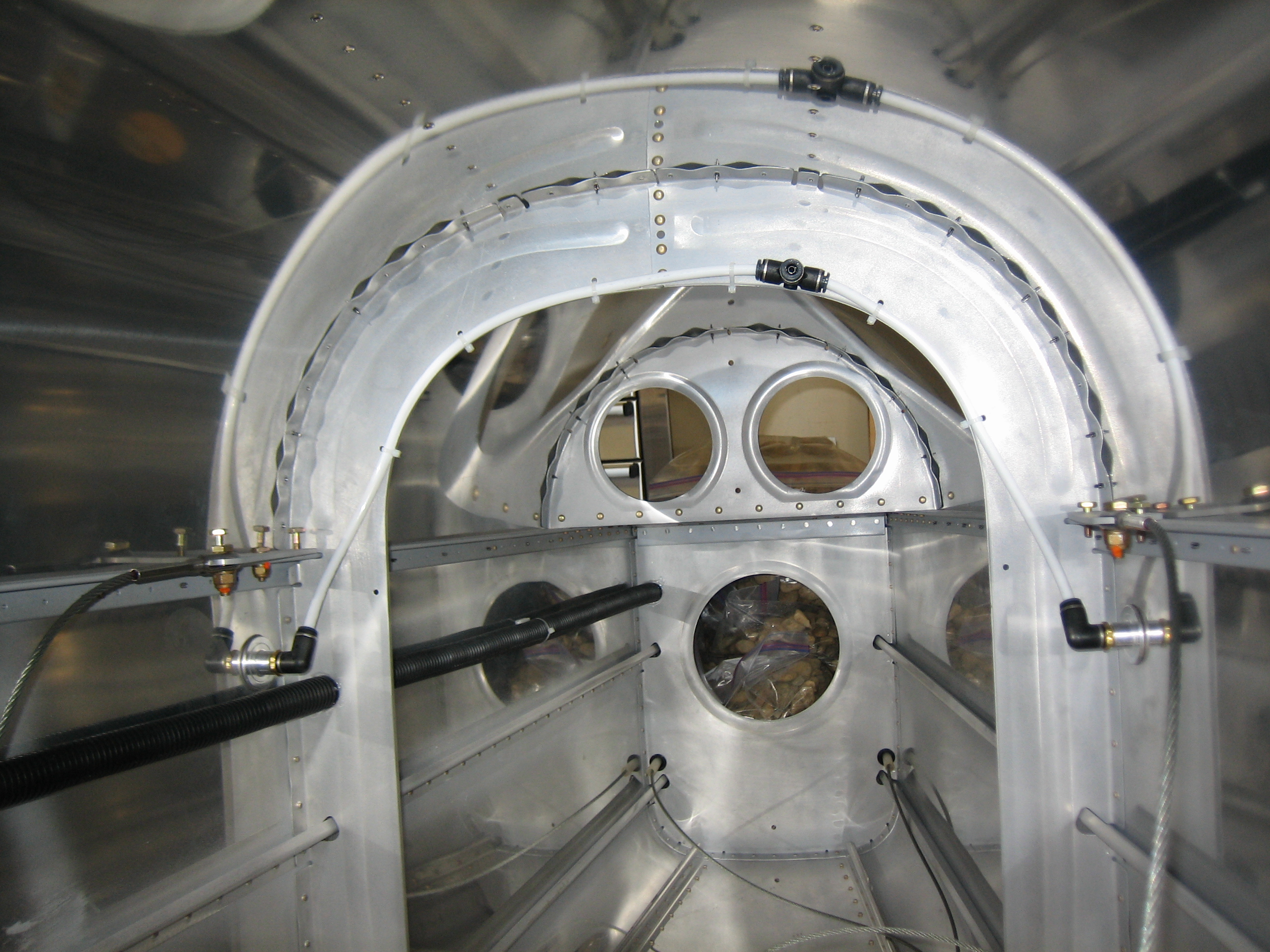
While he was working on that, I moved the tee in the static system up near the top of the bulkhead, right next to where one of the stringers will be installed. Since I decided to mount my ADAHRS from the top rib between F-706 and F-707, I decided it would be simpler to run the static tubing along that top stringer and directly into the back of the ADAHRS. This has the advantage that the static ports are the lowest portion of this part of the static system, so in theory it should allow water to drain out of the system and not make its way into any of the instruments.
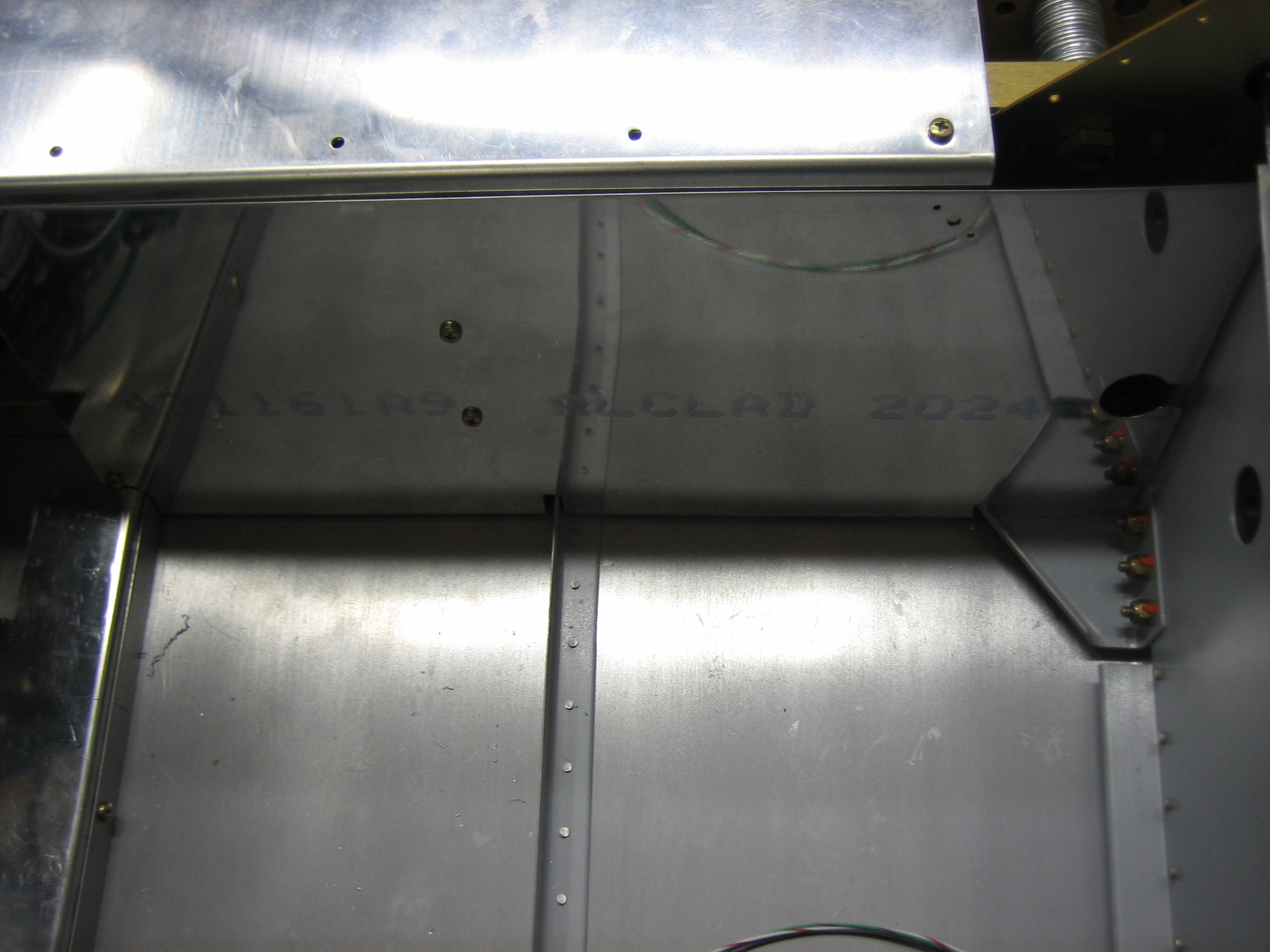
I also worked on the forward half of the center cover. I’ve enlarged the hole at the back half for the fuel line to drop through. I’ll still need to enlarge it a little more to ensure it can never come in contact with the fuel line and abrade it.
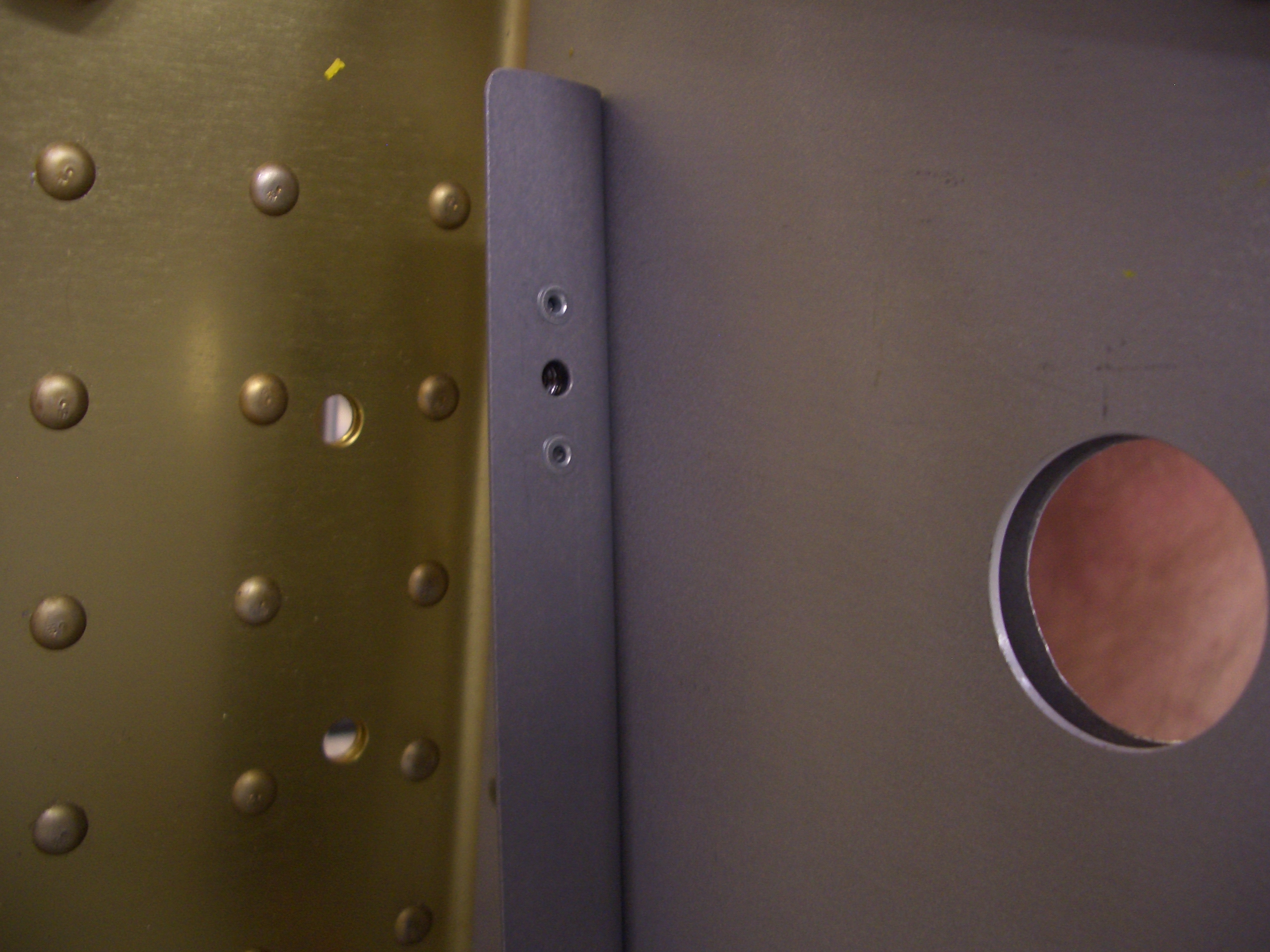
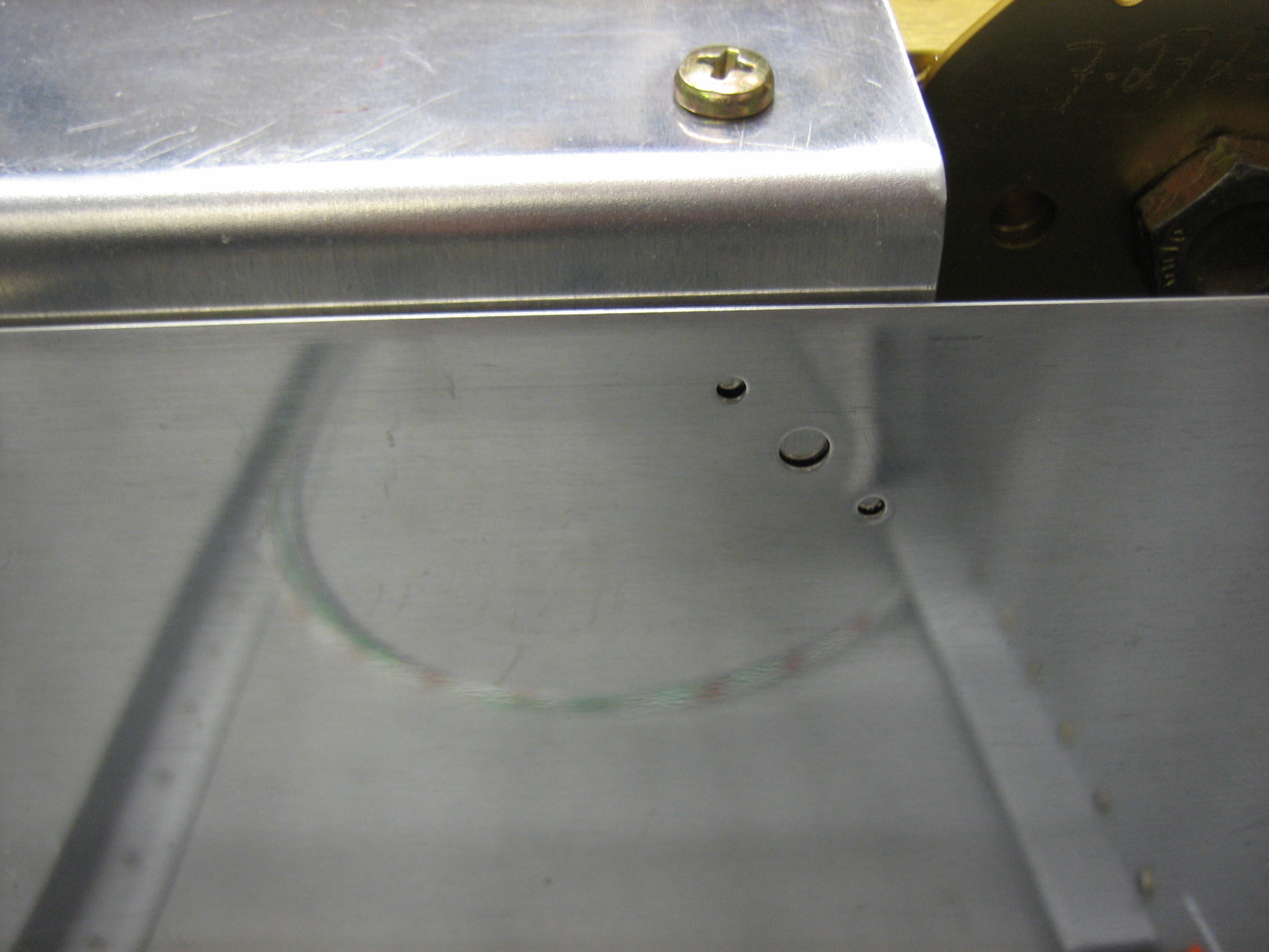
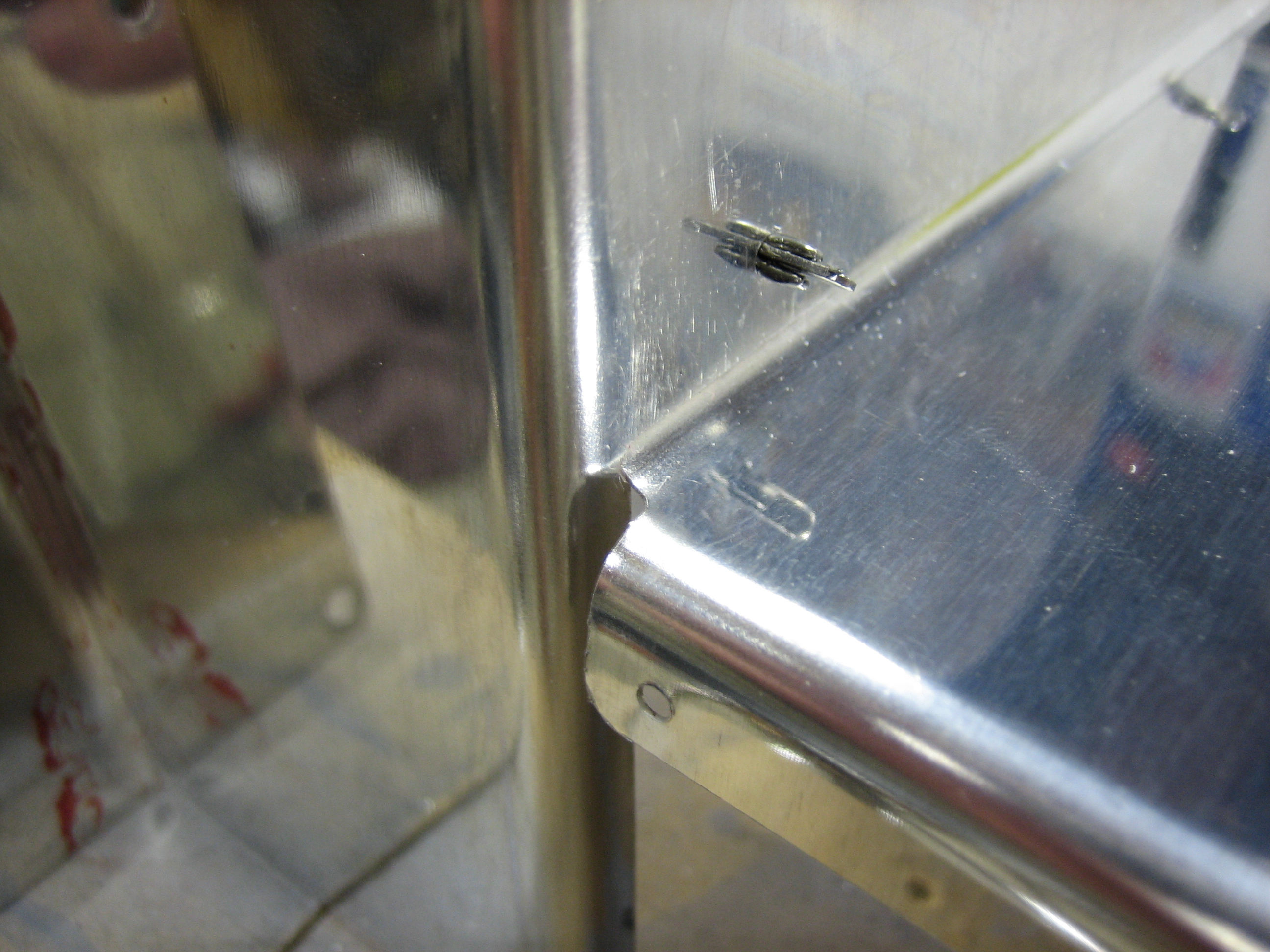
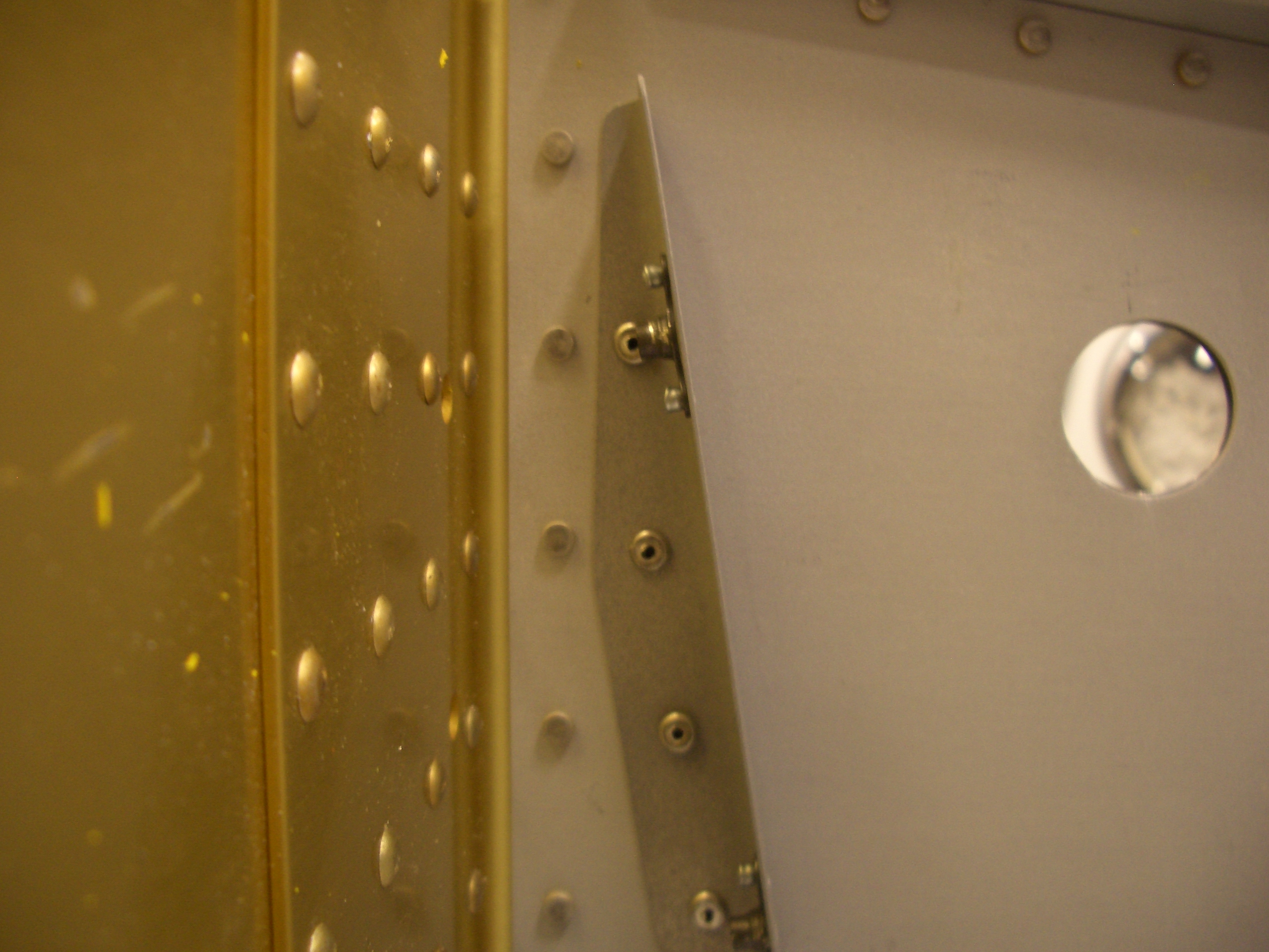
I put the forward spar covers in place. These are supposed to fit under the front edge of the seat pan, but I put it on top initially so that I could match drill the seat pan to one hole in the forward spar cover.
Here’s a closeup of the hole that needs to be drilled. A nutplate will mount on the spar cover and a screw will go through the seat pan and into this nutplate. If I put the spar cover behind the seat pan, I’d be drilling this hole blind.
After match drilling those holes (one per side), I installed the nutplates and reinstalled the covers. Next, I cut the flange off of the fuel selector mounting plate flush with the forward face of the fuel valve cover and cut a notch in the bottom of the fuel valve cover so that it could temporarily sit over the fuel pump. I then took the fuel pump top cover that Van’s sells for the Airflow Performance fuel pump kit and figured out how low I could mount it. Since the Andair pump kit is significantly smaller than the Airflow Performance pump kit, I had previously decided to lower the cover as much as possible. This will require fabricating custom side pieces, but that’s pretty easy.
After determining the mounting point, I drilled the fuel pump cover to the fuel selector cover.
After enlarging the opening in the bottom of the fuel selector cover, I fit the flange from the fuel pump cover inside the fuel selector cover. These holes will get dimpled and these pieces will be riveted together along with the side covers I need to fabricate.
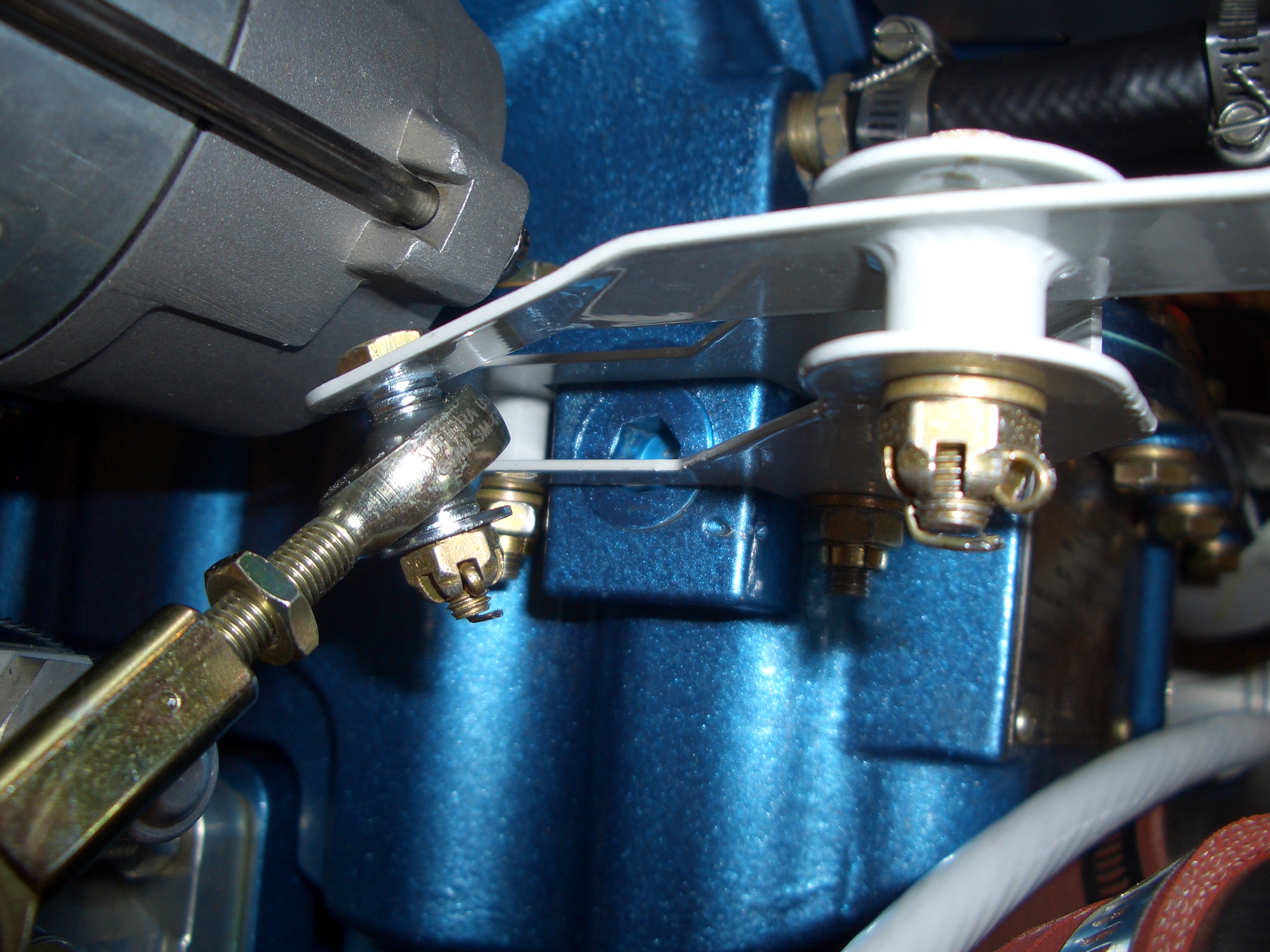
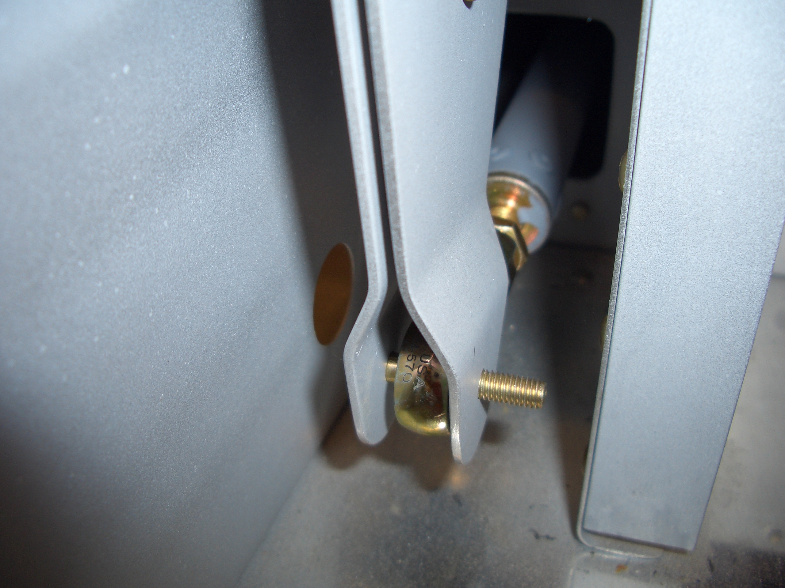
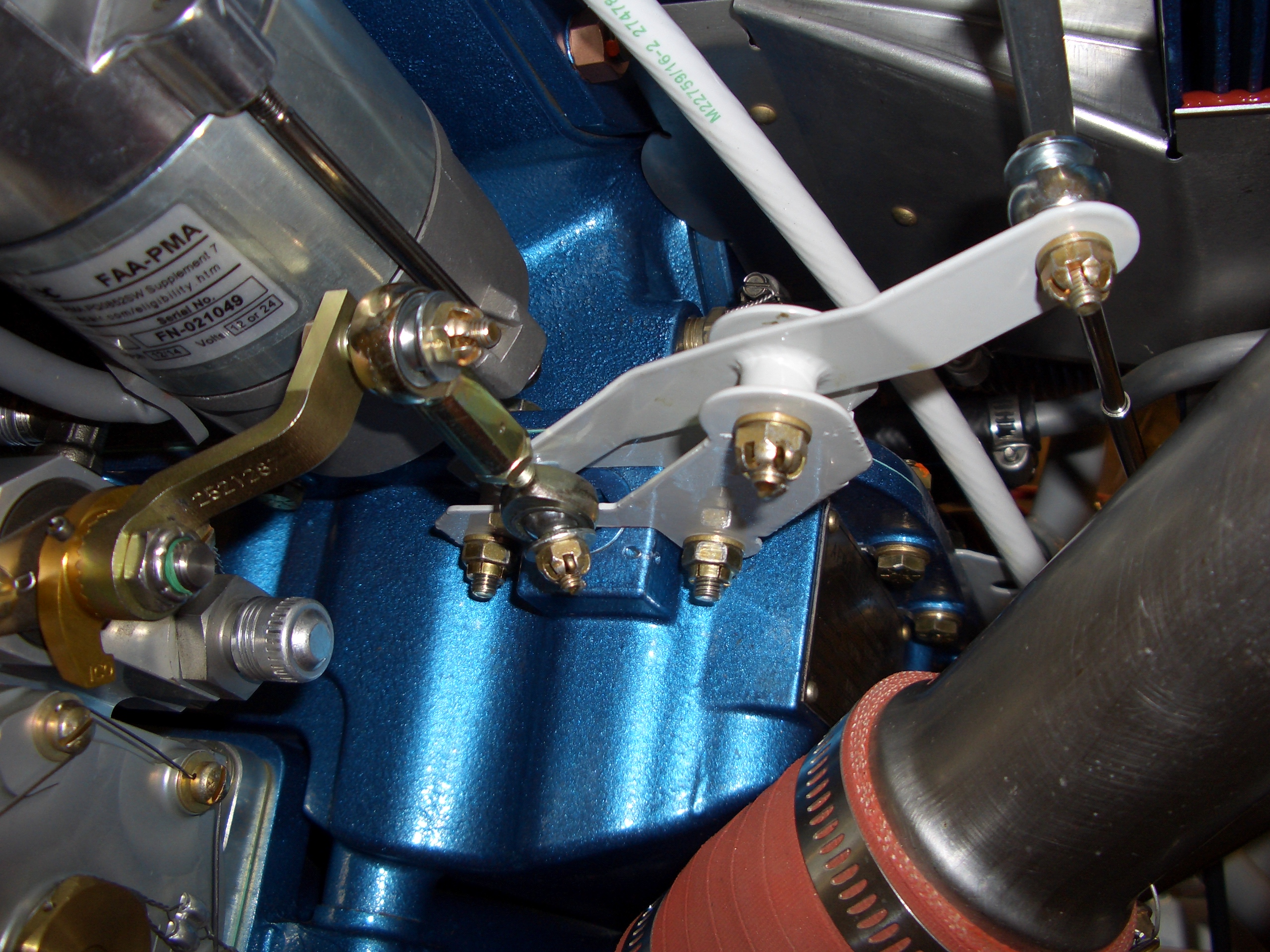
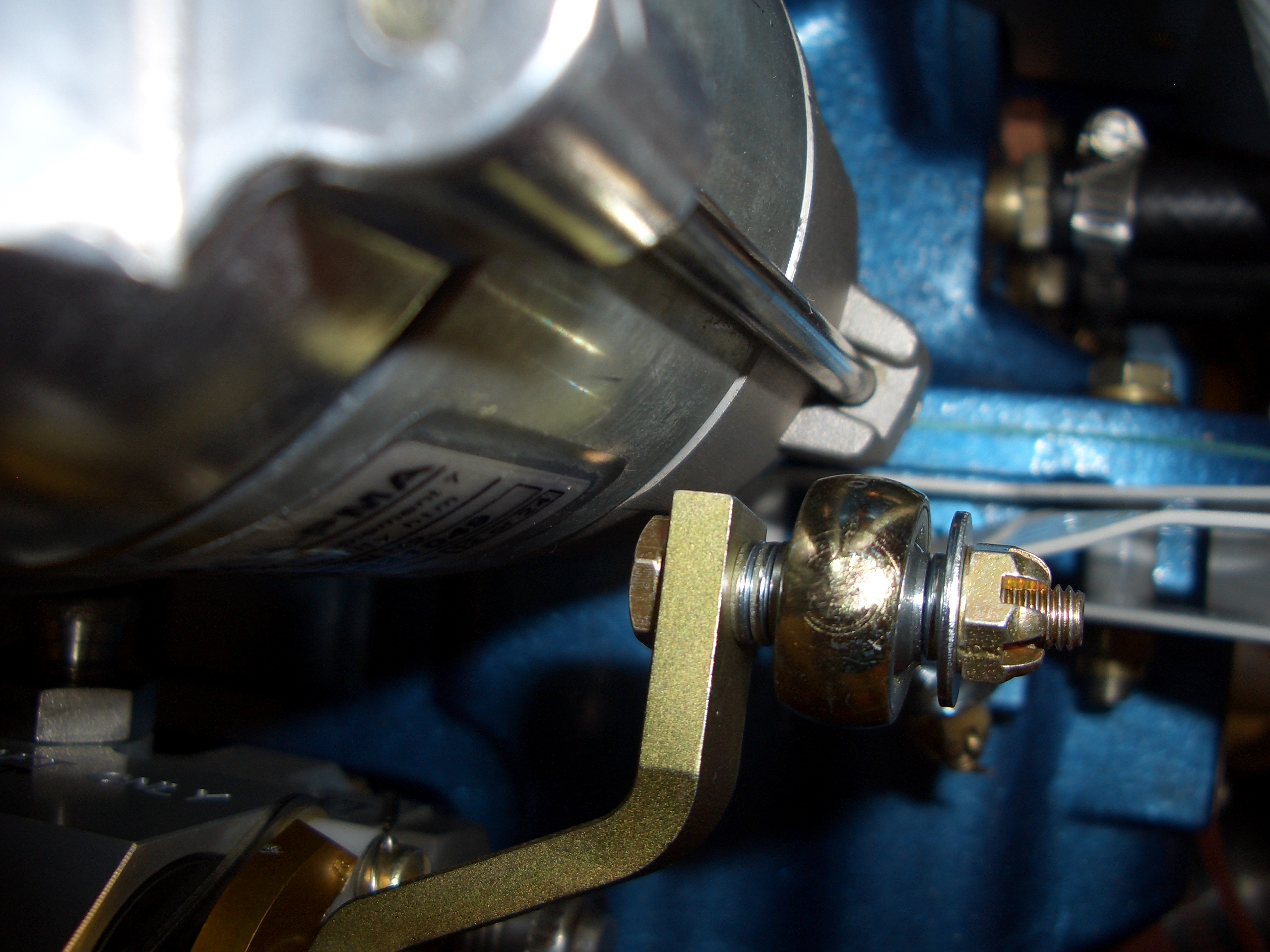
The shorter mixture arm arrived from Precision Airmotive today. I installed it and then spent a little time adjusting the various linkages to get proper movement. Here is the linkage in the idle cutoff position.
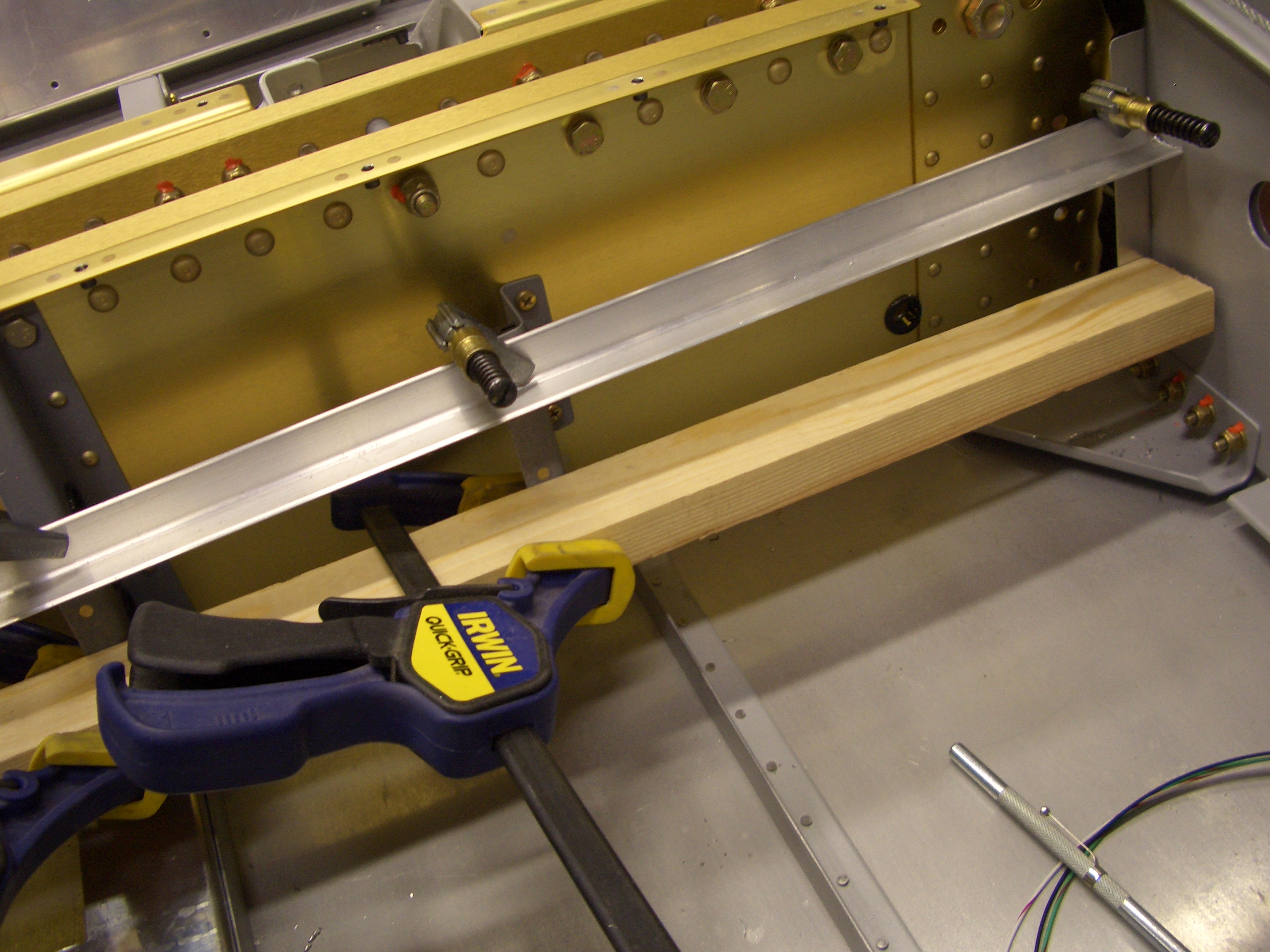
I used a couple of straight edges clamped to the other spar cover attach brackets to define the position of the outer attach angles. I then duct taped the angle in place and match drilled it to the gear webs.
I blind riveted the attach angles to the gear webs using LP4-3 rivets. I had to grind down the tips of the rivets and pull them in small steps (pounding the rivets further in each time).
I also installed the nutplates using MK-319-BS rivets since there wasn’t enough room to get a normal rivet squeezer in here after riveting these to the gear webs (and the nutplates couldn’t be installed first since they would have interfered with squeezing the LP4-3 rivets). I just realized that I forgot to cut the notch in these for the fuel line grommet. I’ll have to do that in place.