High Altitude Training

My buddy Dan and I flew up to Beale Air Force Base today to go through their high altitude training program.  The five painful hours we spent in ground classes was made up for by the one hour we got to spend in the altitude chamber.

They first took us up to 5k ft and back down to ensure everyone could clear their ears successfully.  We then spent 30 minutes at sea level breathing 100% oxygen to purge some of the nitrogen from our blood.  After a quick mask seal check (which one unfortunate person failed and had to be pulled from the chamber), we started our ascent.  We climbed at about 3k fpm to 8k ft and then leveled off briefly.  We then climbed at 10k fpm to FL180 where we removed our masks for a couple of minutes.  After replacing our masks, we climbed again at 3k fpm to FL250.  We took off our masks and they had us perform a quiz with a few simple questions and a maze.  They told us to start the quiz right after taking off our masks, but I completed it before I really felt anything, so it didn’t really show how your brain starts malfunctioning.  After a couple of minutes, I started having a couple of minor symptoms including euphoria and skin tingling, so I turned on the emergency oxygen and put the mask back on.  Finally, we dropped by to FL180 and took off the masks one last time to check our night vision.  I really didn’t notice much of a difference in my vision with and without the oxygen at this altitude, but most people did.  Finally, we dropped back to sea level and did a debrief.

Overall, I think the experience was worthwhile, but I was really hoping to experience more loss of mental ability.  No one in the chamber really did anything odd or even appeared to lose their ability to think clearly.  Some people did lose their color or get blue lips, but that was about it.

Fuel Vent, Brake Pedals, Brake Fluid Reservoir

Now that the proseal has cured, I trimmed the excess screen and mounted the fuel vents through the floor just behind the firewall.

I got some parts back from the metal finisher where I had them black anodized.  The primary components were the parts for the brake pedals.  I quickly riveted them together.  The brake pedals will get a lot of wear over the years, and this should keep them looking like new.

Since I was already paying the minimum shop fee, I threw in a couple of other components.  This is the brake fluid reservoir and transducer manifold.

I mounted the brake pedals as well as the master cylinders and some rudder pedal extensions from JD Air Parts.  These parts are all black anodized, so they look great together.

Finally, I mounted the rudder pedals in the plane and torqued all of the bolts.

The last thing I did for the night was to install the brake fluid reservoir on the firewall.

You can see on the inside that I used some firewall sealant around the hole through the firewall.

Pressure Transducer

I drilled the firewall and rib for the pressure transducer.  I installed a couple of nutplates on the rib and put the various fittings and transducers on the manifold.  I then temporarily installed the manifold on the firewall.  This will have to come off one more time to rivet the rib to the firewall.  I also may have to adjust the fittings and possibly swap out the fuel fitting (lower) for a 90º fitting instead of the 45º fitting that I installed.  Just like all of the other fittings forward of the firewall, I’m using steel here.

On the other side, I installed some brass plugs to cap off the extra ports.

I spent the rest of the night planning out the remaining things that need to mount to the firewall and making sure I had all of the hardware on hand.

Worked on Firewall Components

I needed to install a bunch of things on the firewall before hanging the engine.  Since the engine mount hadn’t been torqued to the firewall yet, I pulled it with the gear still attached to give me better access.

I laid out the ANL current limiter and shunt and drilled mounting holes through the firewall.

Then I laid out for nutplates and some extra rivets to tie the doubler to the firewall.  The nutplate on the right (at an angle) ties the shunt into the firewall reinforcement angle.

I also laid out for the fuel pass through and installed the throttle cable pass through.  As with other firewall penetrations, this is all steel,  It can also swivel up to 50º to accommodate cables that have to penetrate the firewall other than orthogonally.

I then drilled out for the fuel pass through and some rivets for the doubler.

I replaced the AN3C bolts holding the parking brake on with some flush head stainless steel screws.  Where there is nothing attaching on the forward side of the firewall, I’m trying to keep everything flush so the firewall is easier to keep clean.  I still need to install the rivets in the doubler, but it’s too late to make noise tonight.  I also installed the pass-throughs for the mixture and prop cables.

Since the parking brake is in for good now, I installed and torqued rigid lines connecting the parking brake to the firewall pass-throughs.  It looks like the line on the right is touching the right cable pass through, but there’s plenty of clearance.

Hung the Engine!

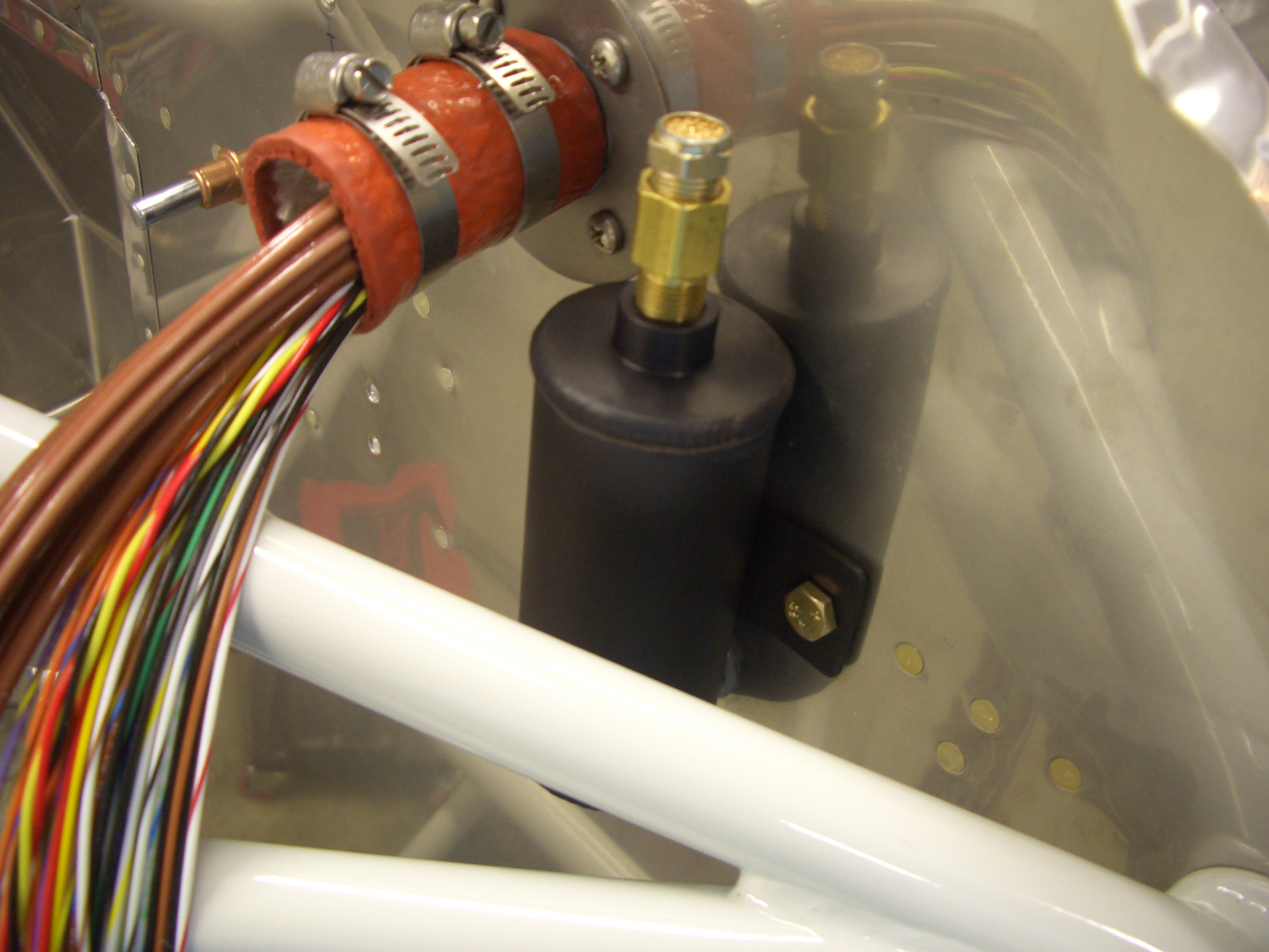
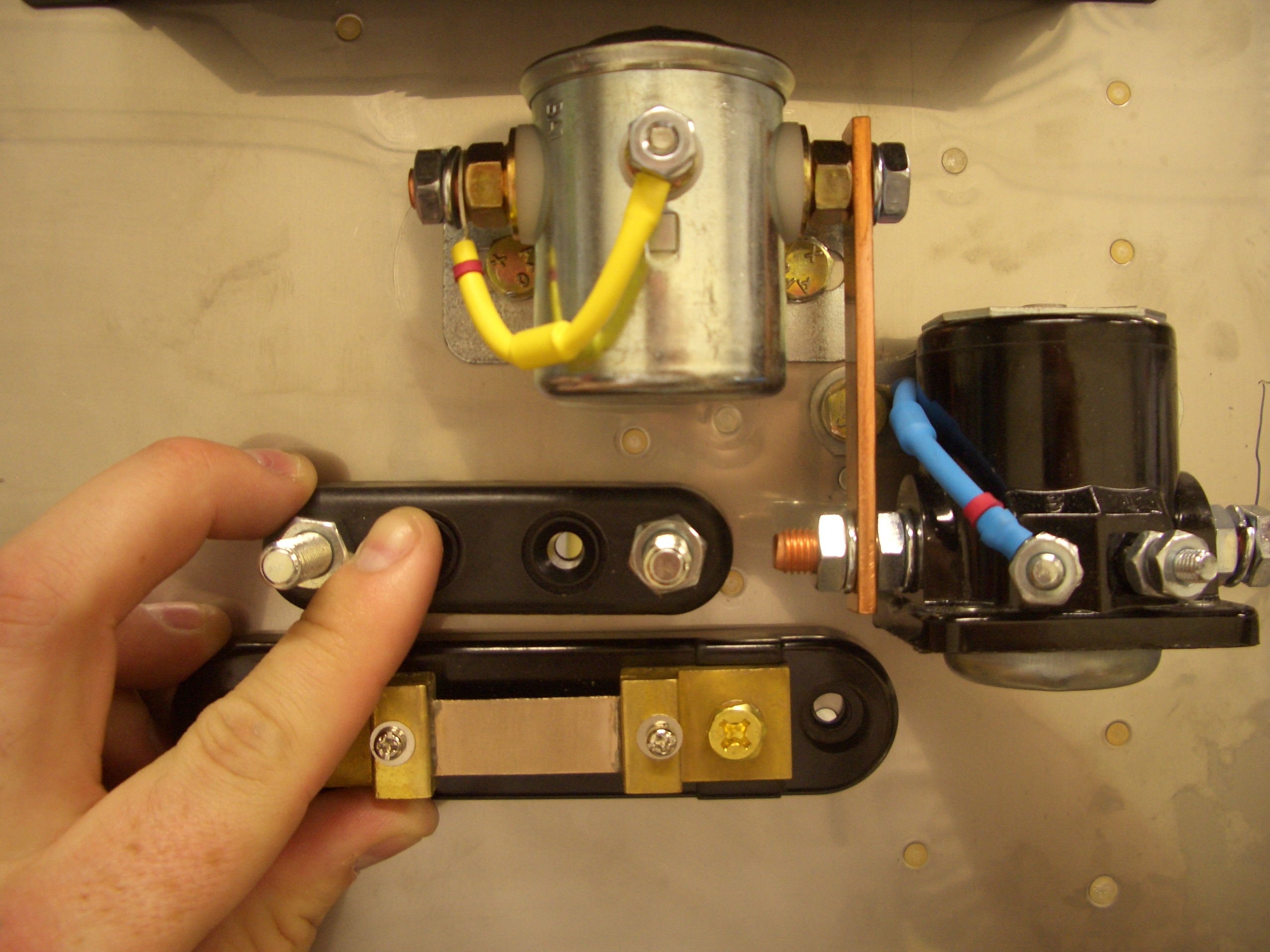
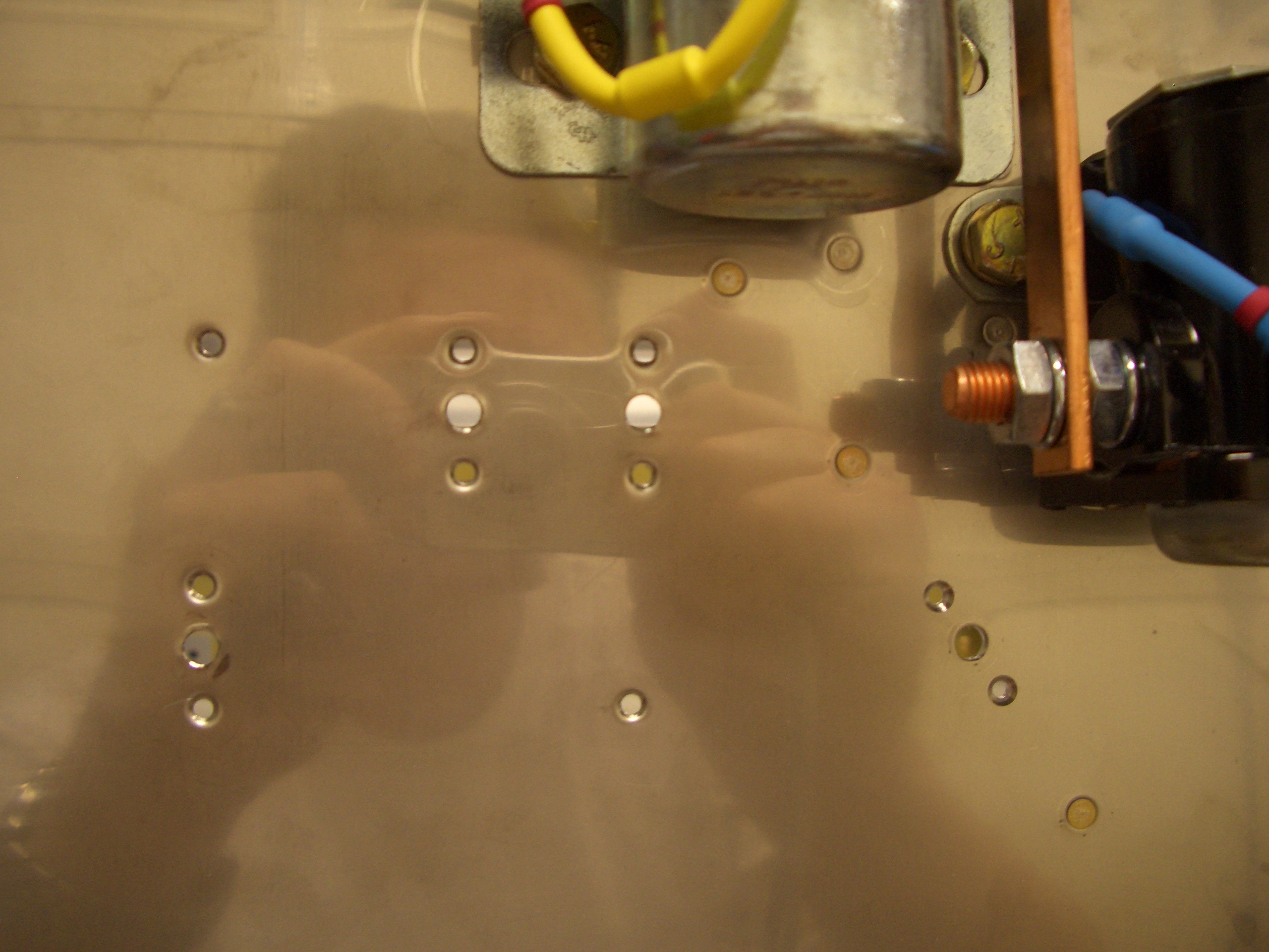
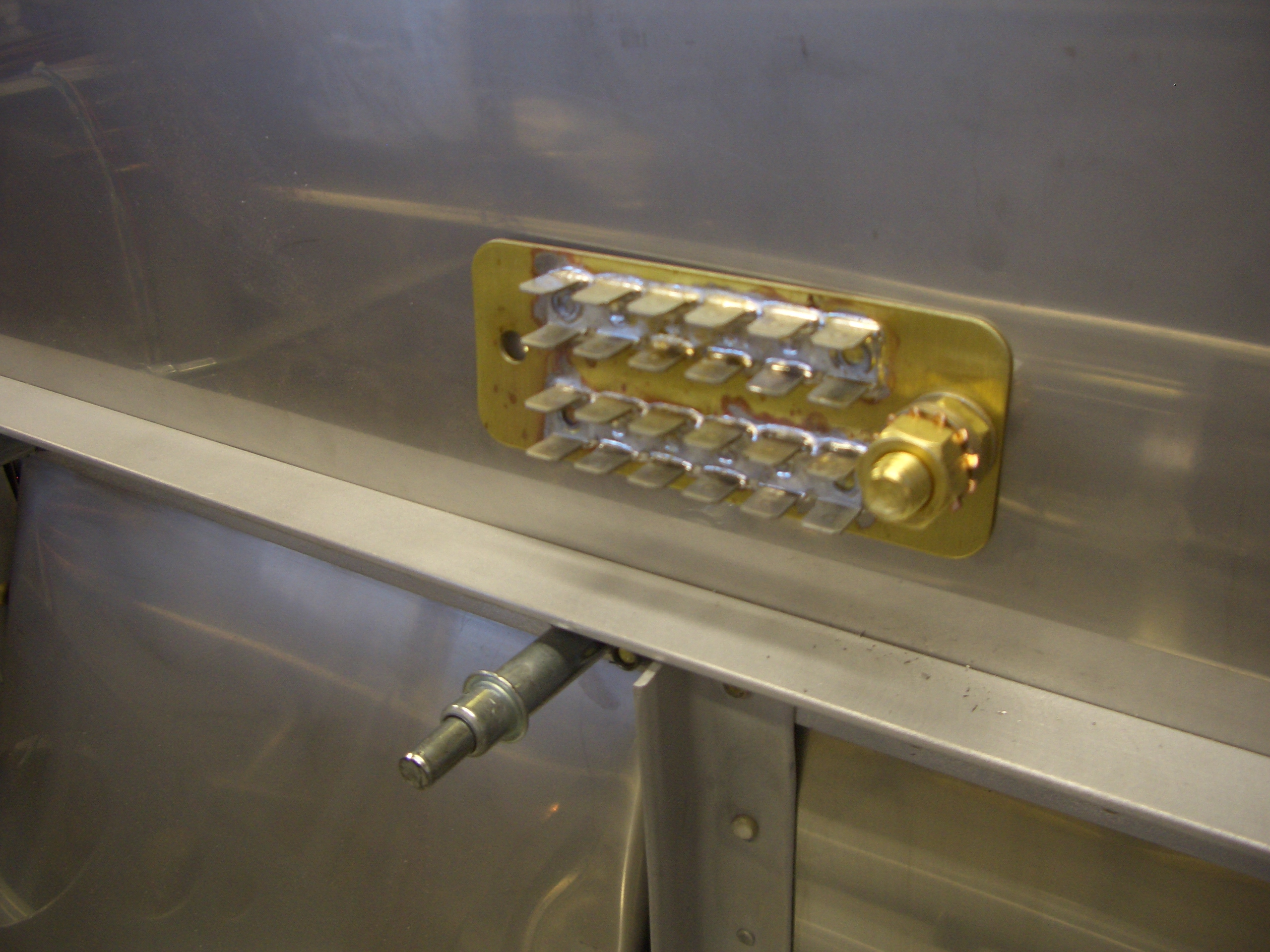
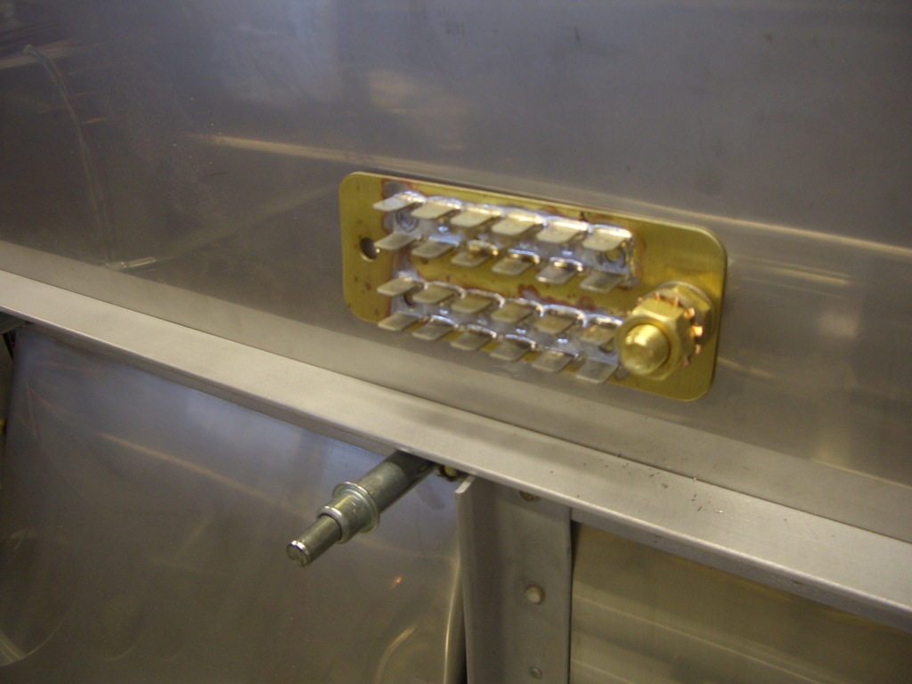
My buddy Andre came over today.  We set the goal of hanging the engine by the end of the day.  There were still a bunch of things that needed to be done to the firewall before we could do that though.  First up was to drill the firewall for the ground block.  Here is the back side of the firewall showing the “forest of tabs” for grounding all of the items in the plane at the same point.  This helps to reduce (if not eliminate) sources of electrical noise in the aircraft.

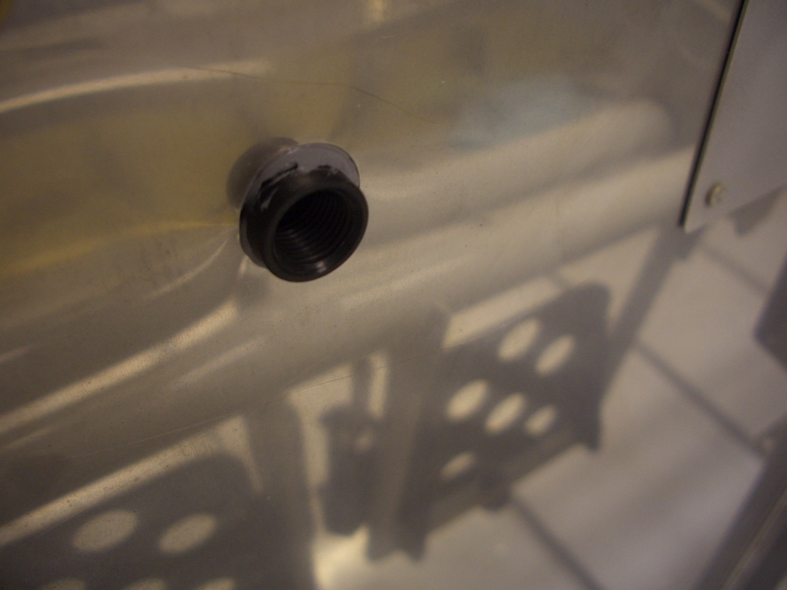
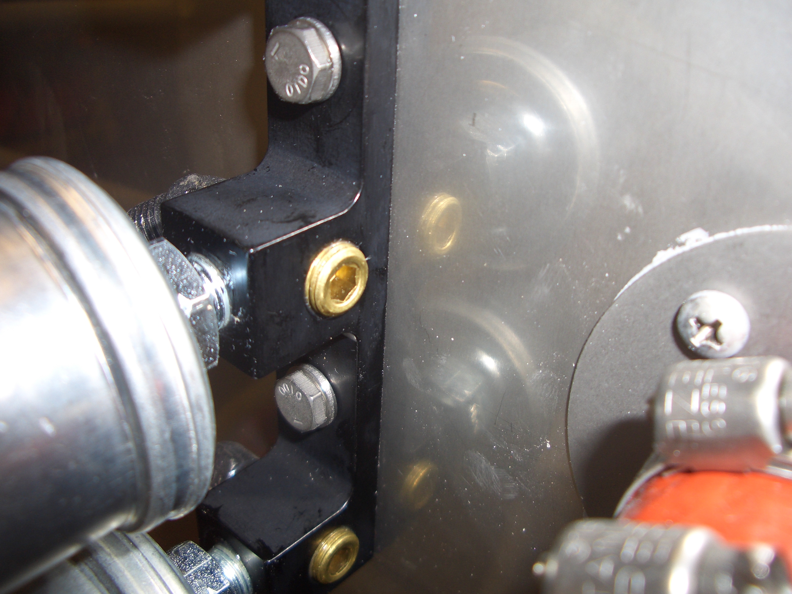
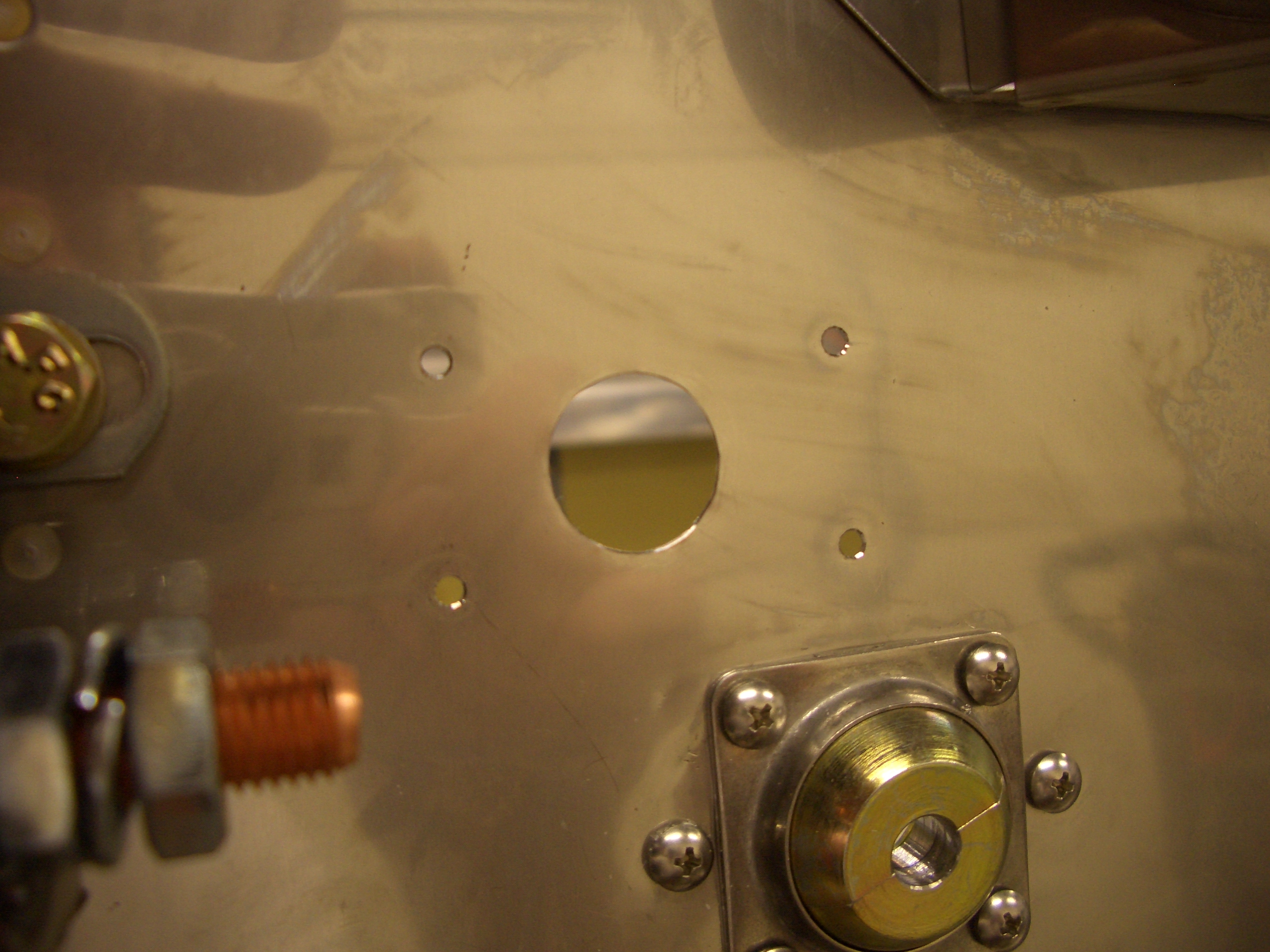
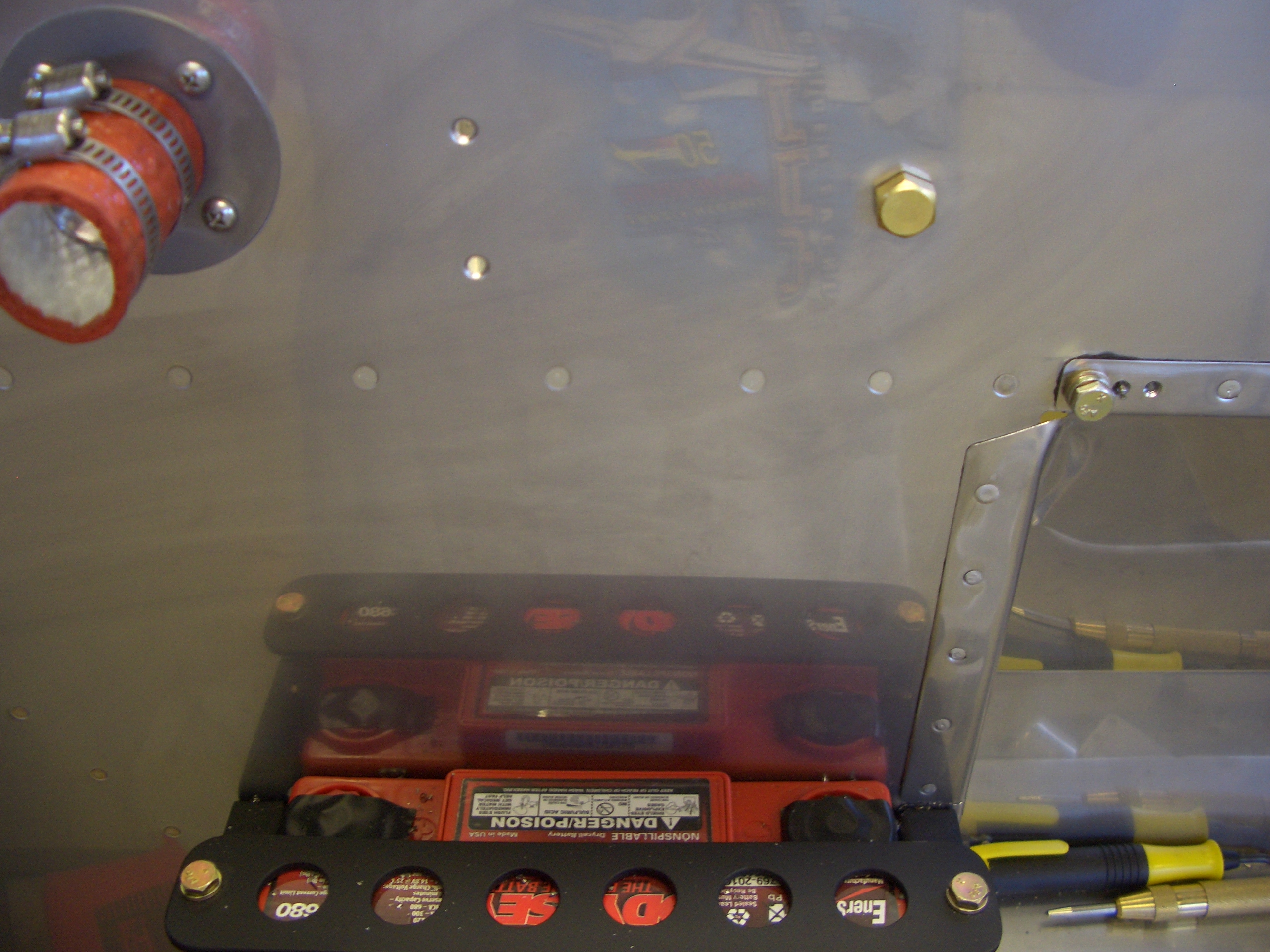
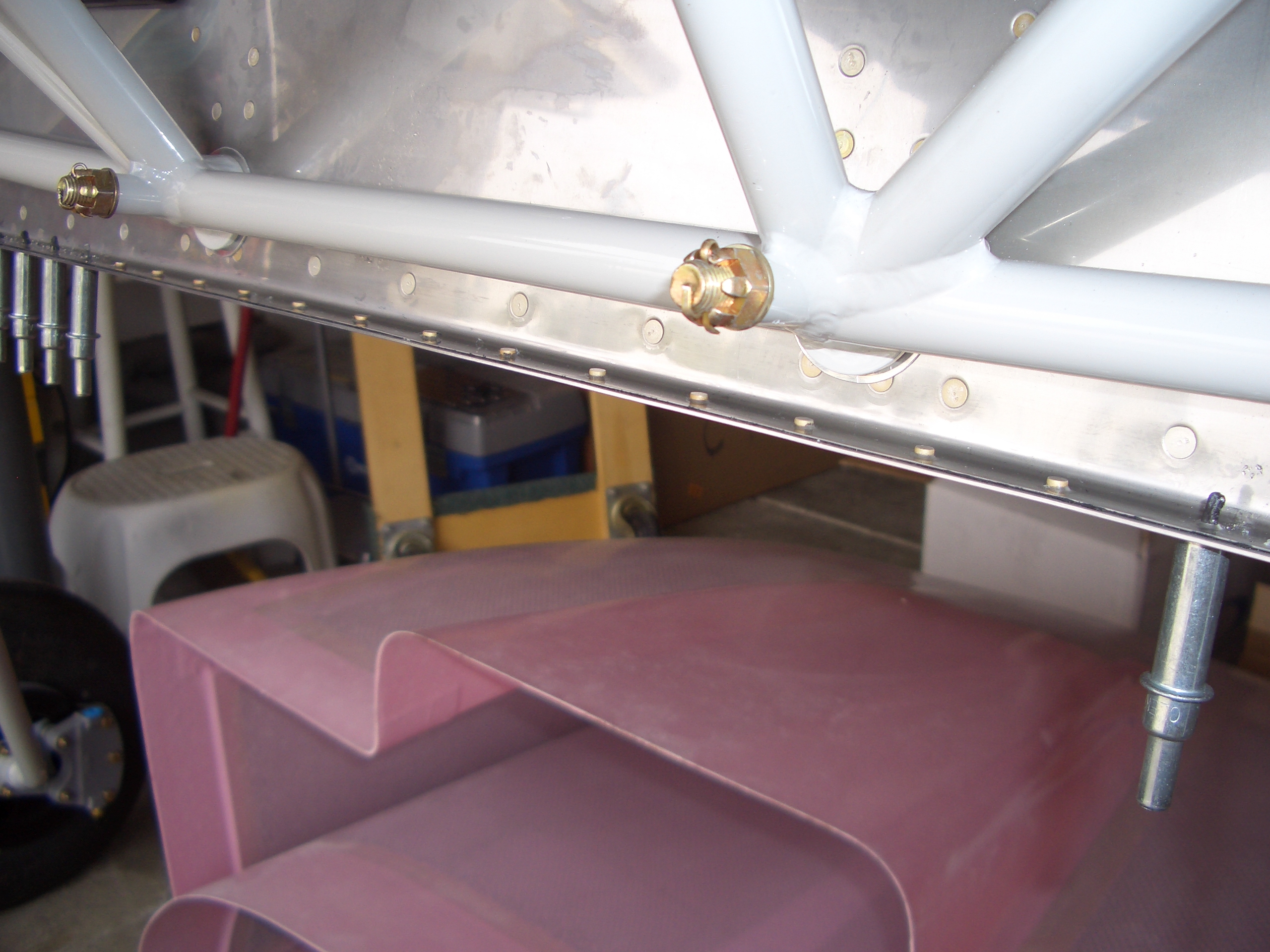
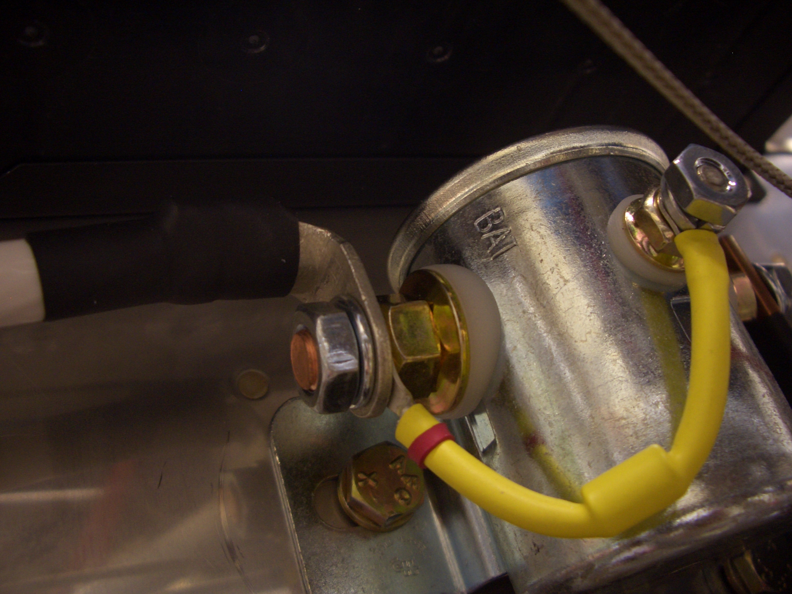
Here is the forward side showing where the mounting bolt is relative to the battery.  I positioned it high enough that I can remove the battery without hitting the bolt.

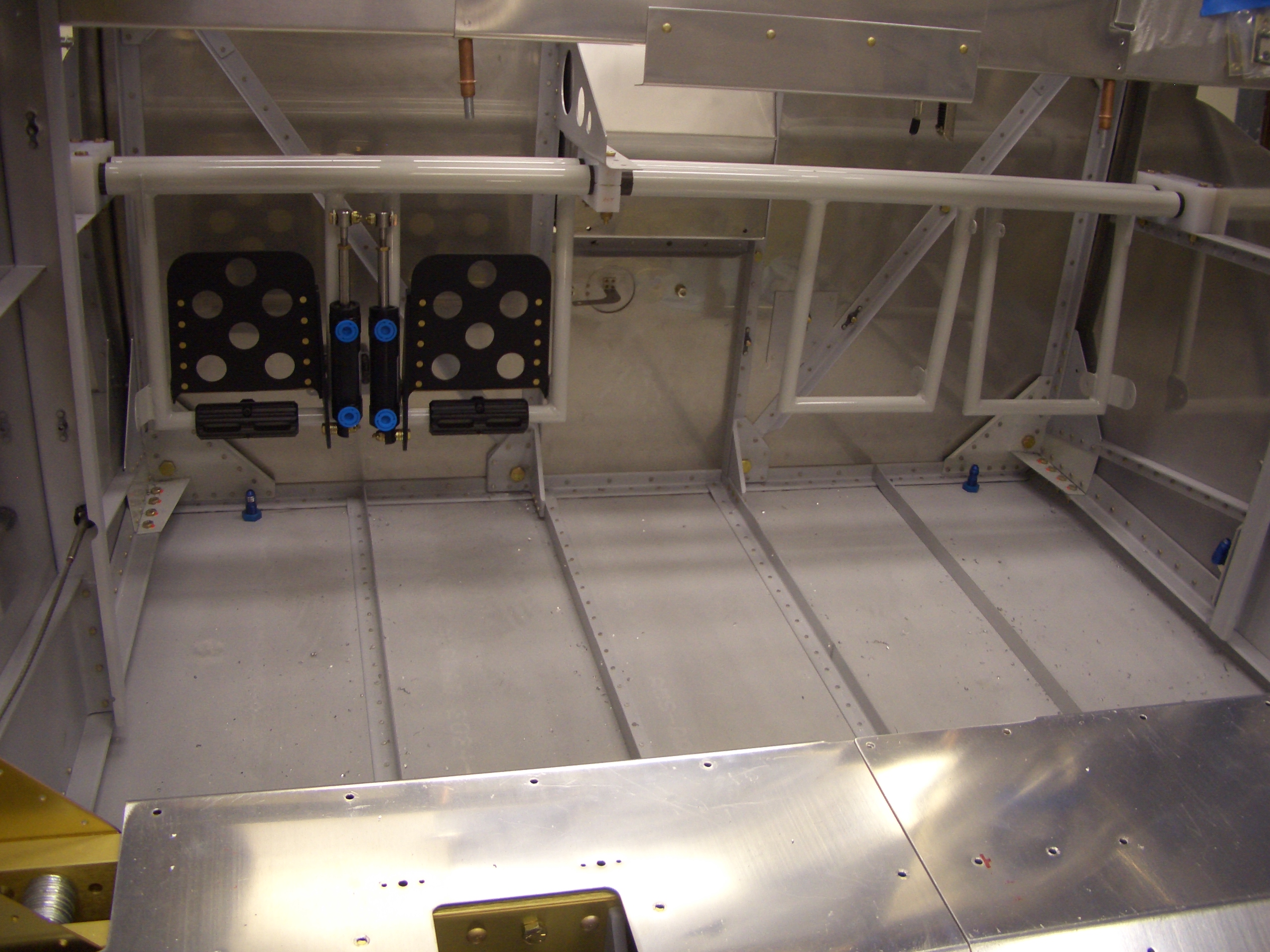
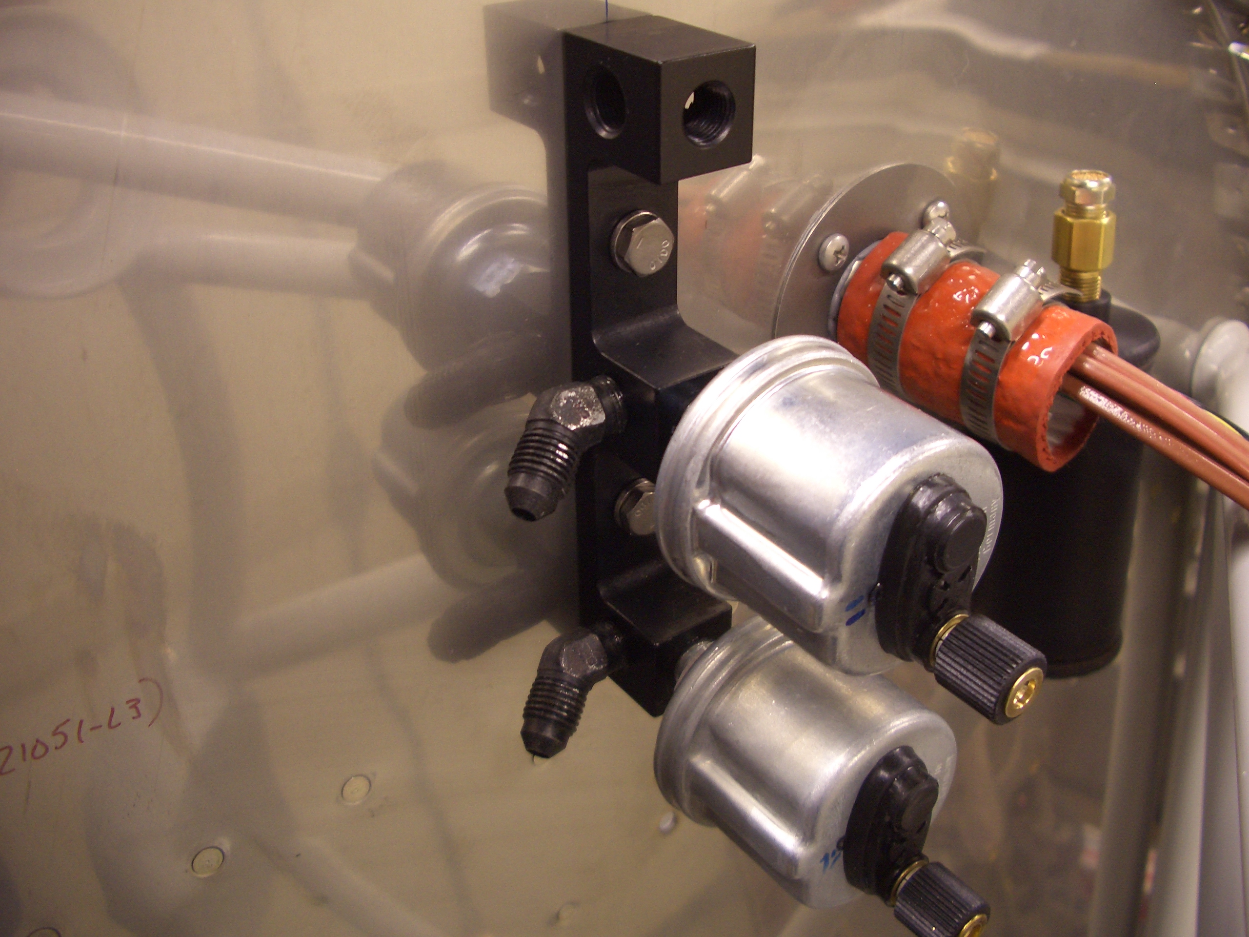
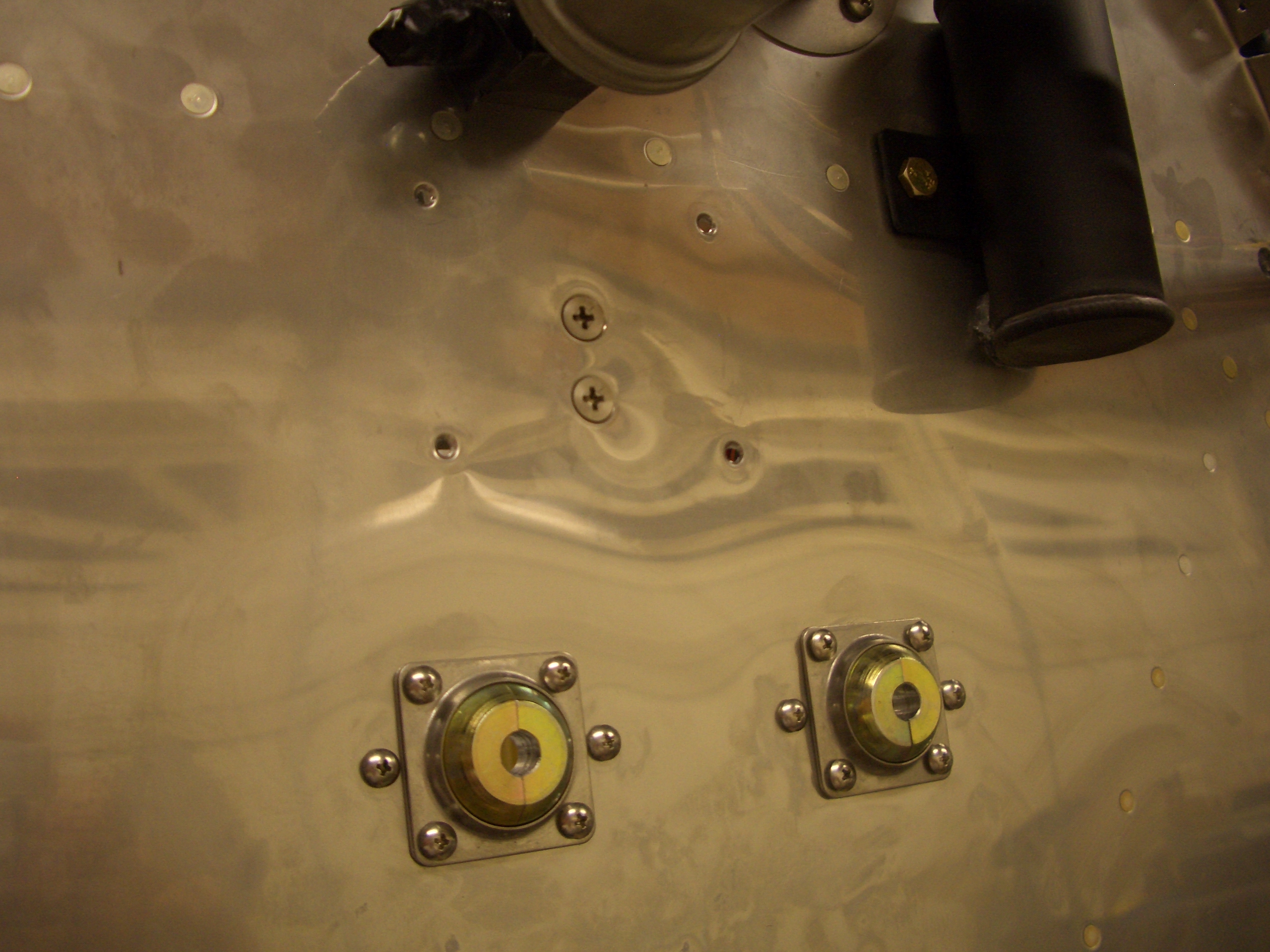
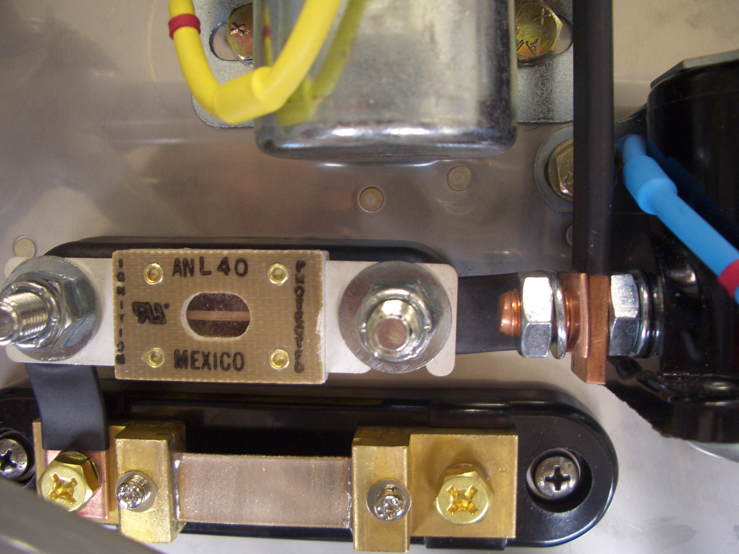
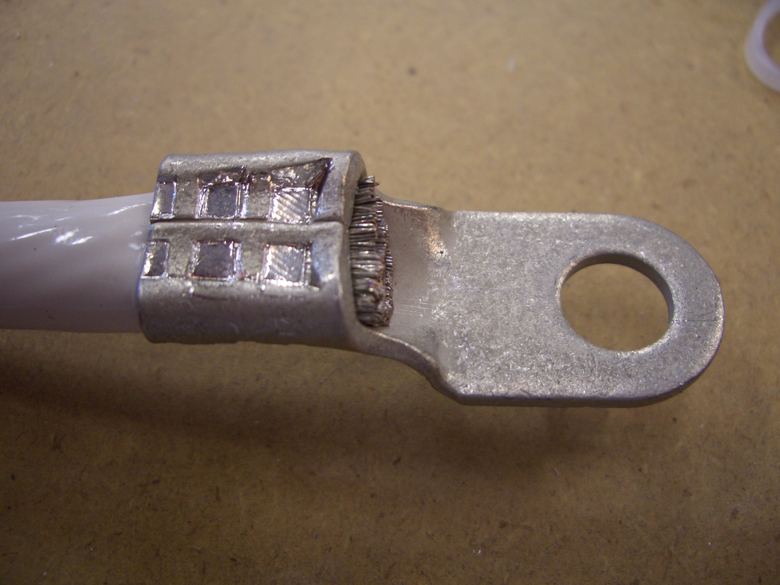
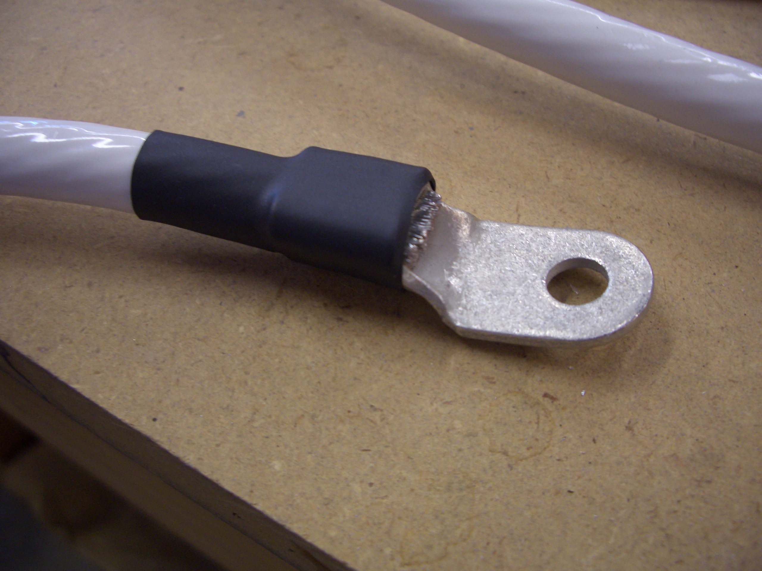
We primed and riveted the doublers for the shunt and ANL current limited and fabricated the bus bars that connect them to the input side of the starter contactor.

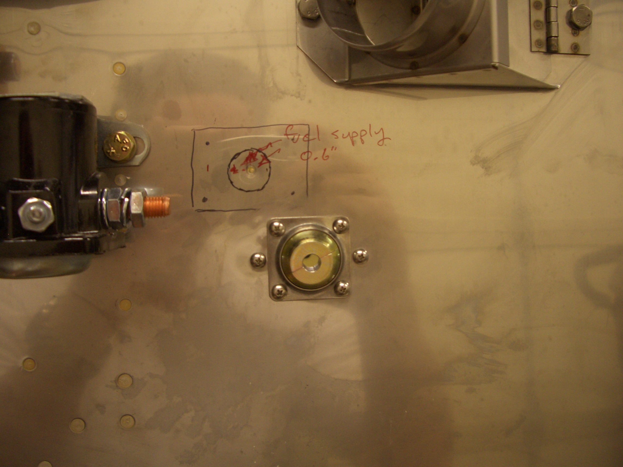
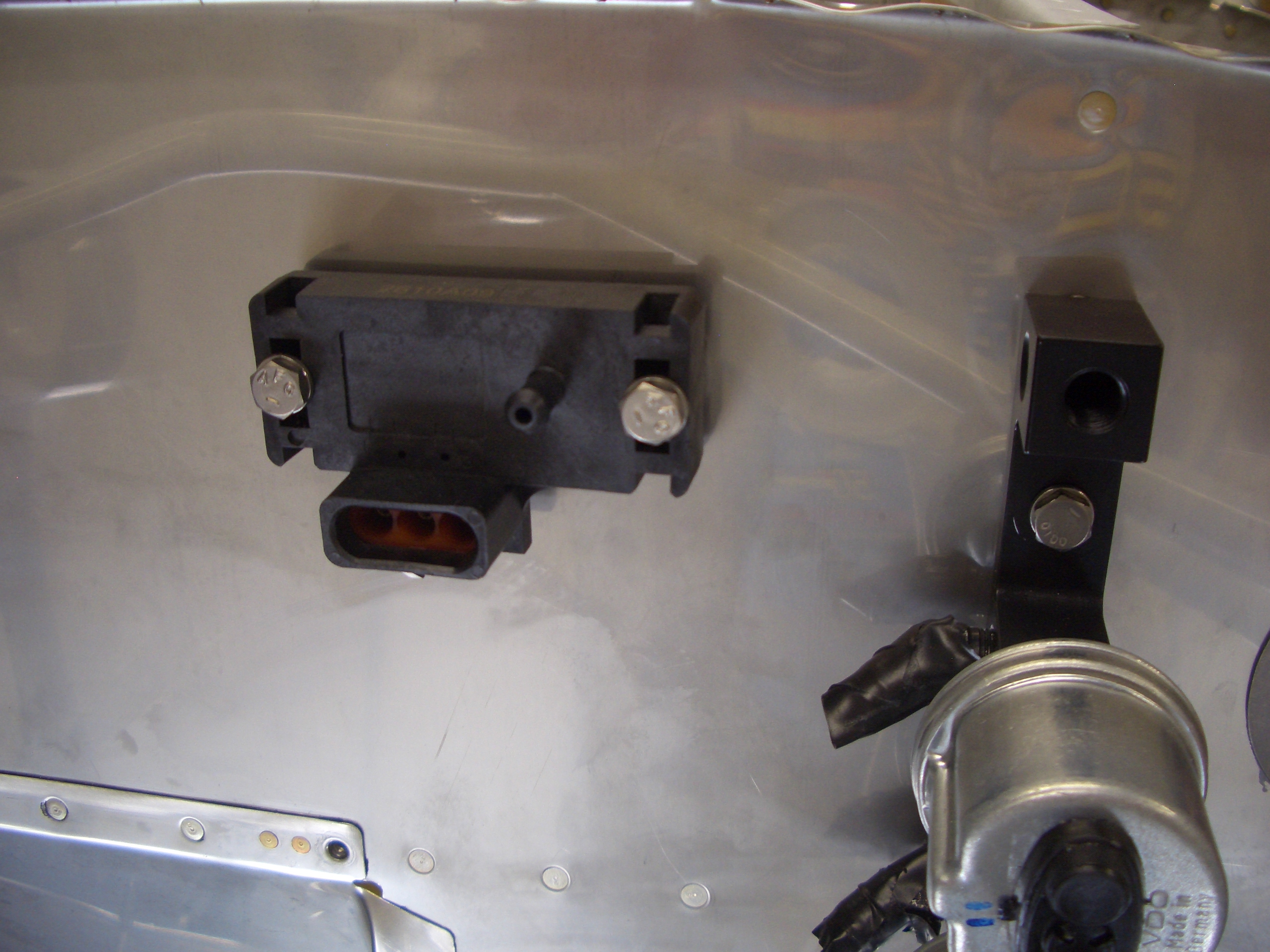
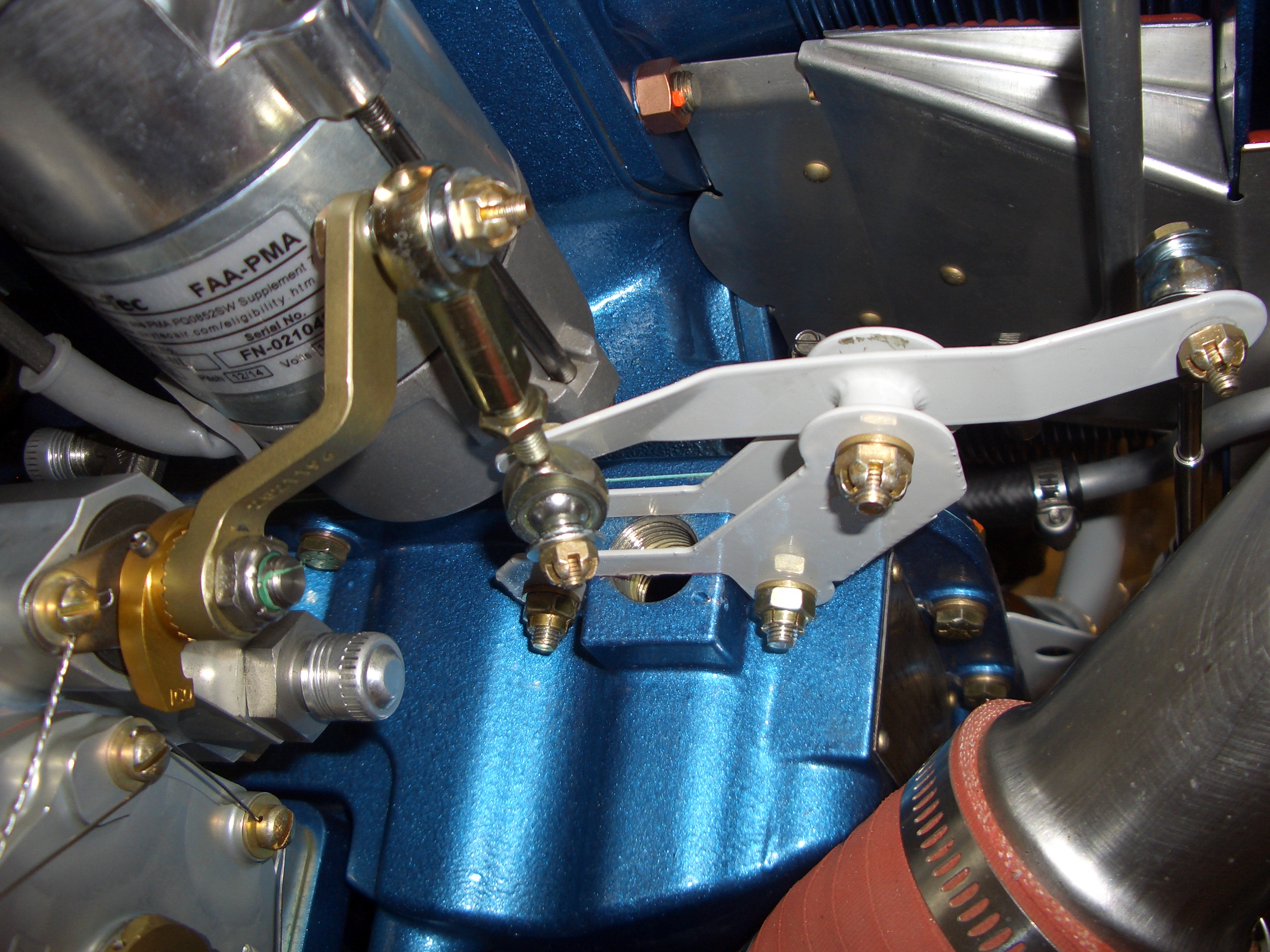
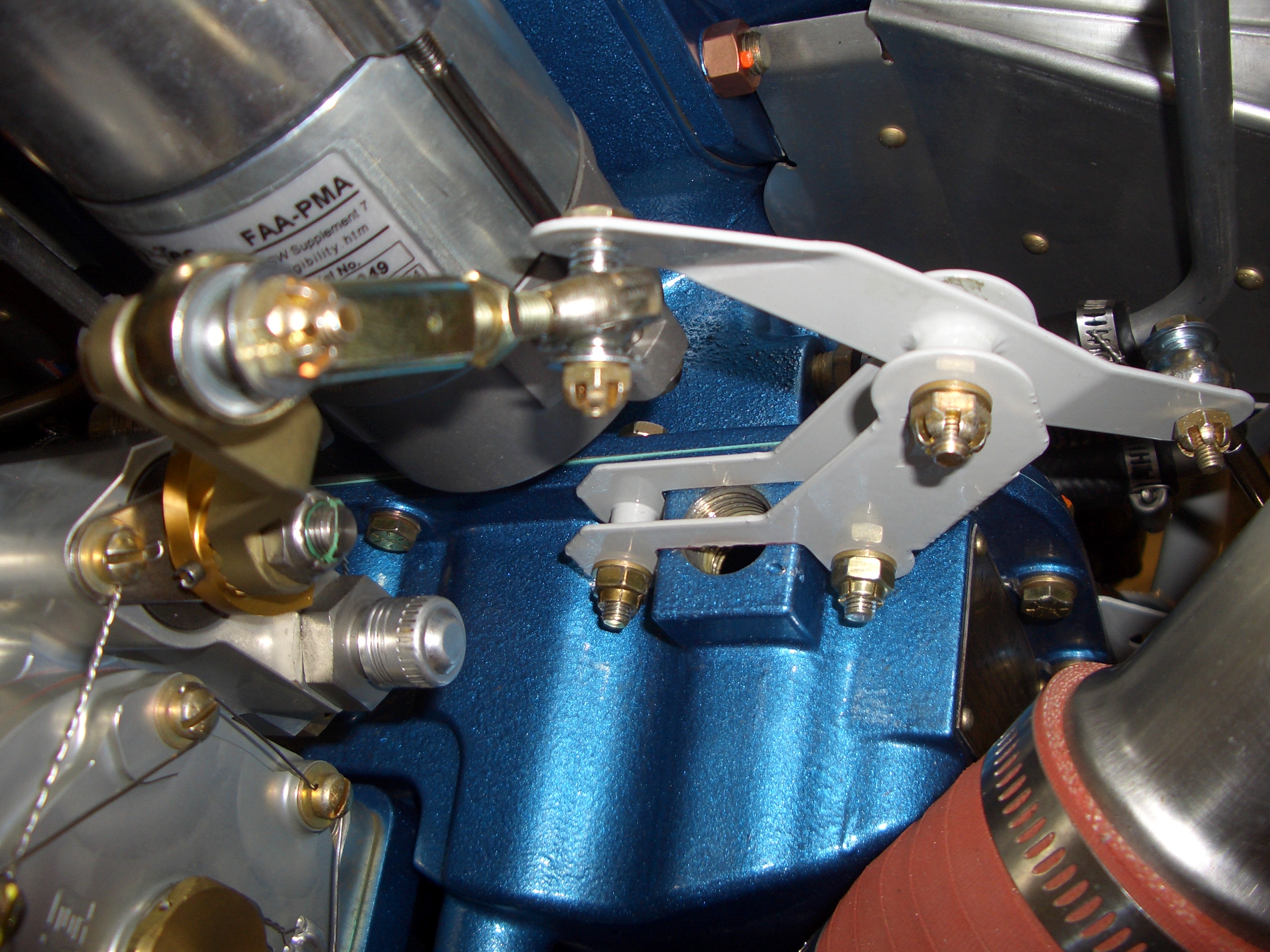
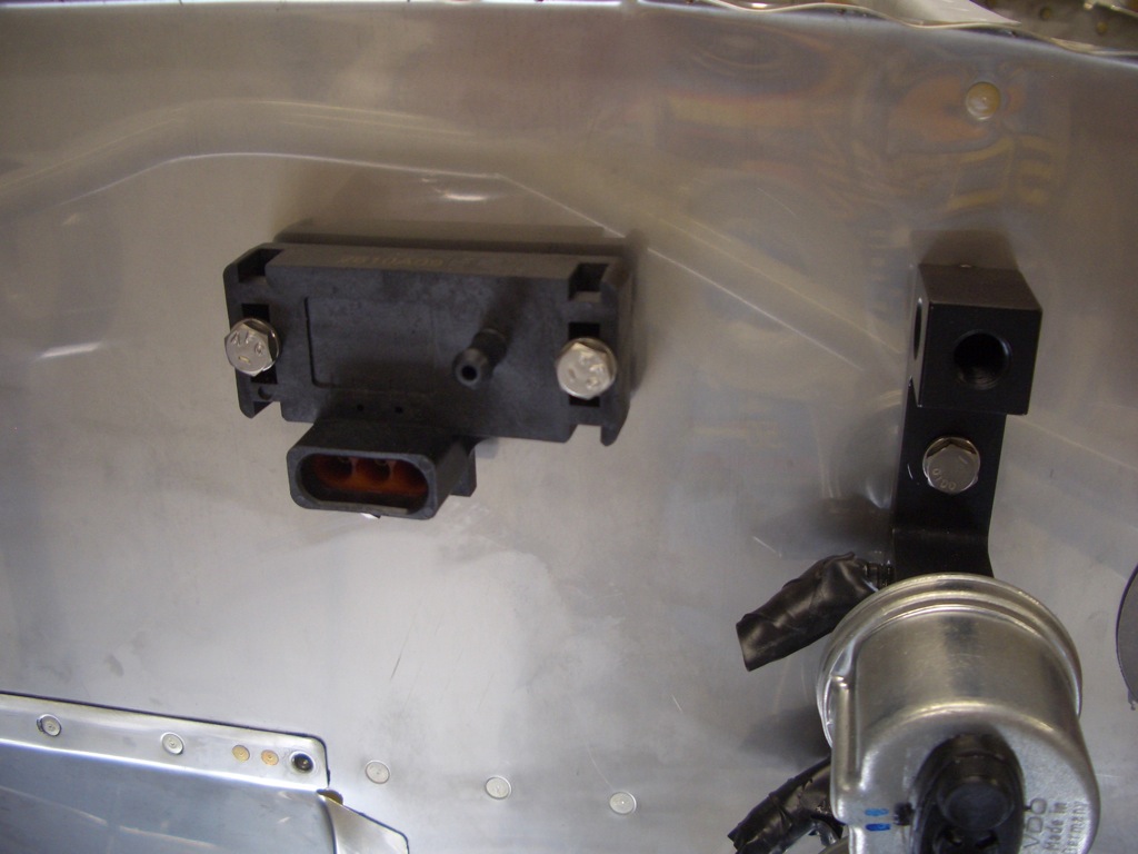
Next up, we drilled and mounted the Dynon manifold pressure sensor to the firewall.  Finally, we riveted on a couple of nutplates and the parking brake doubler.  You can also see that we riveted on the forward ribs and then reinstalled the pressure transducer.  Afterward, I reinstalled the engine mount with landing gear and torqued/cotter pinned the nuts.

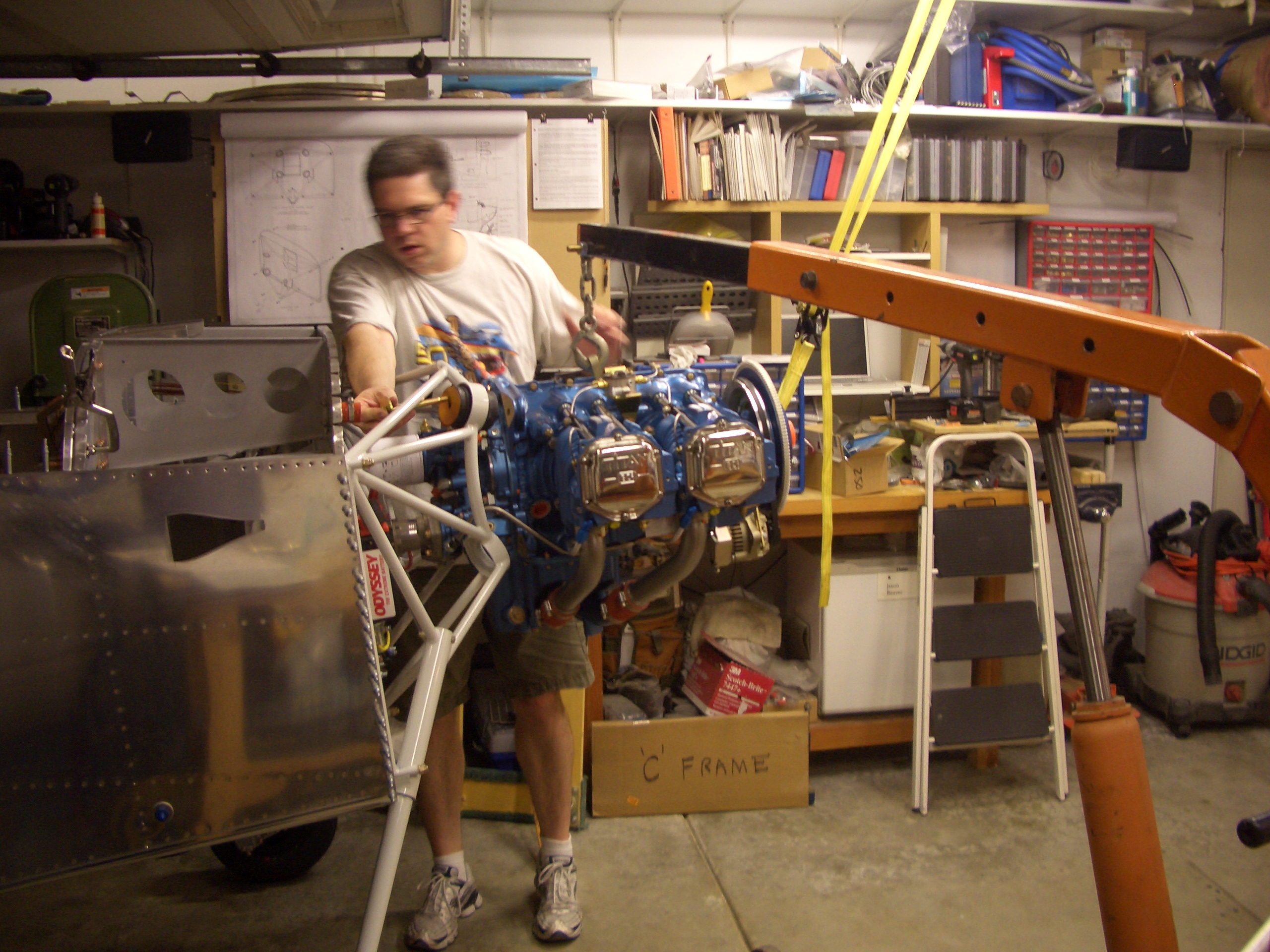
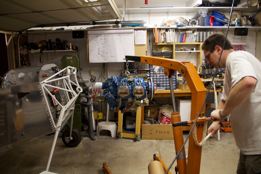
After dinner, we got started hanging the engine.  I had been planning on having a few guys from EAA chapter 338 stop by and help, but after reading about the experience of a few builders, I thought we’d give it a try.  We turned the plane around so the engine hoist had some smooth concrete to roll on.  Here, we’ve just lifted the engine pallet up off the ground so that I can undo the bolts holding the engine to the pallet.  I actually set the pallet gently back on the engine hoist legs so that it wouldn’t put any load on the bolts as I took them off.

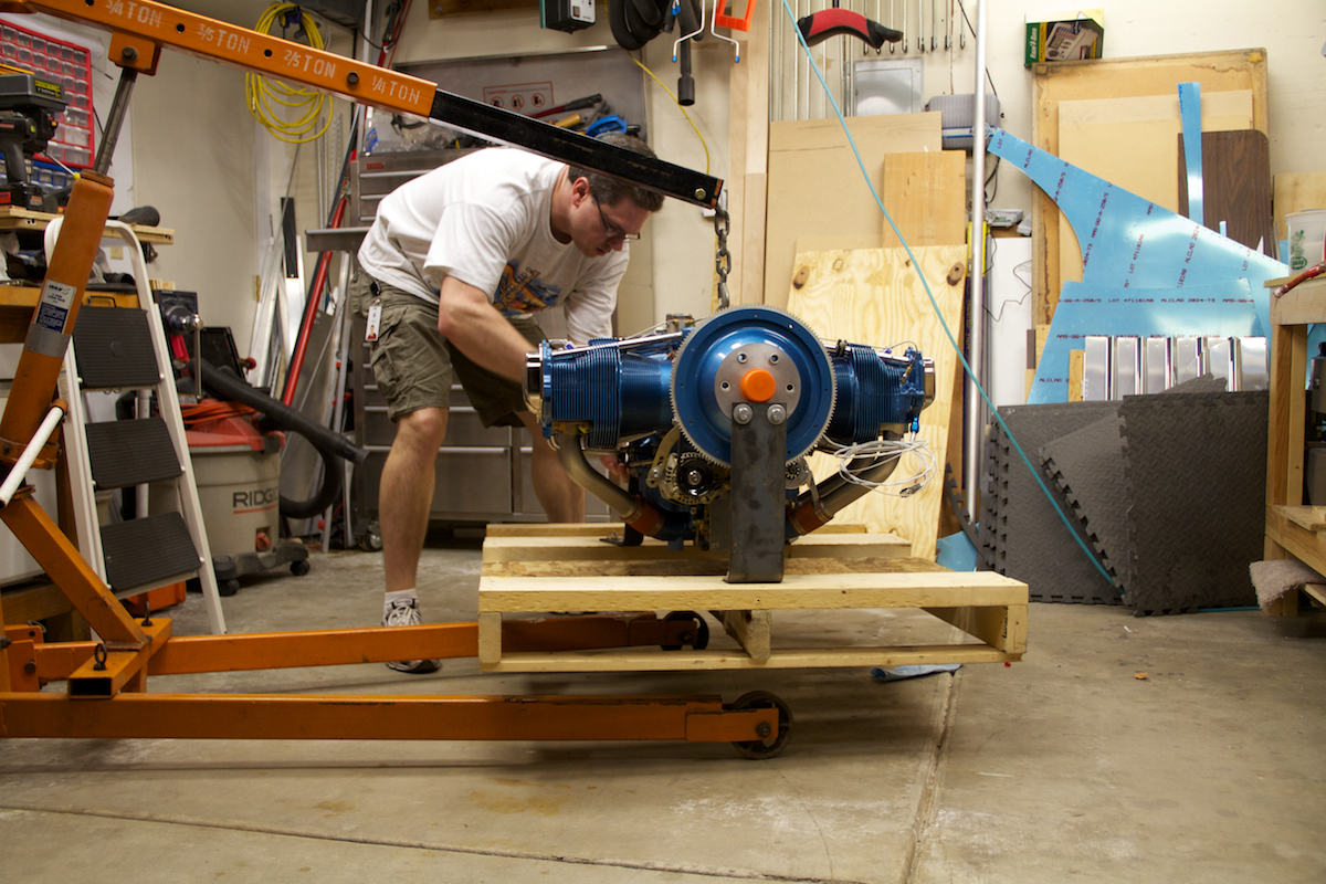
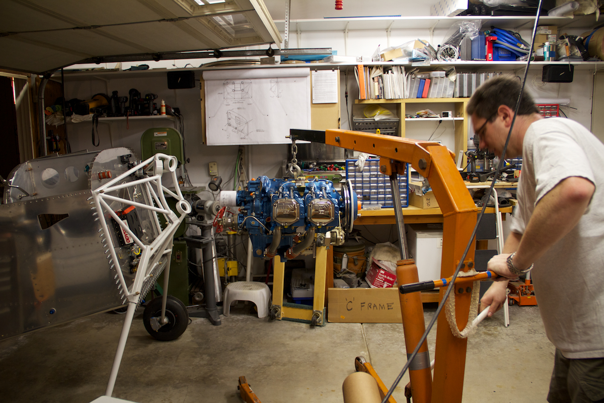
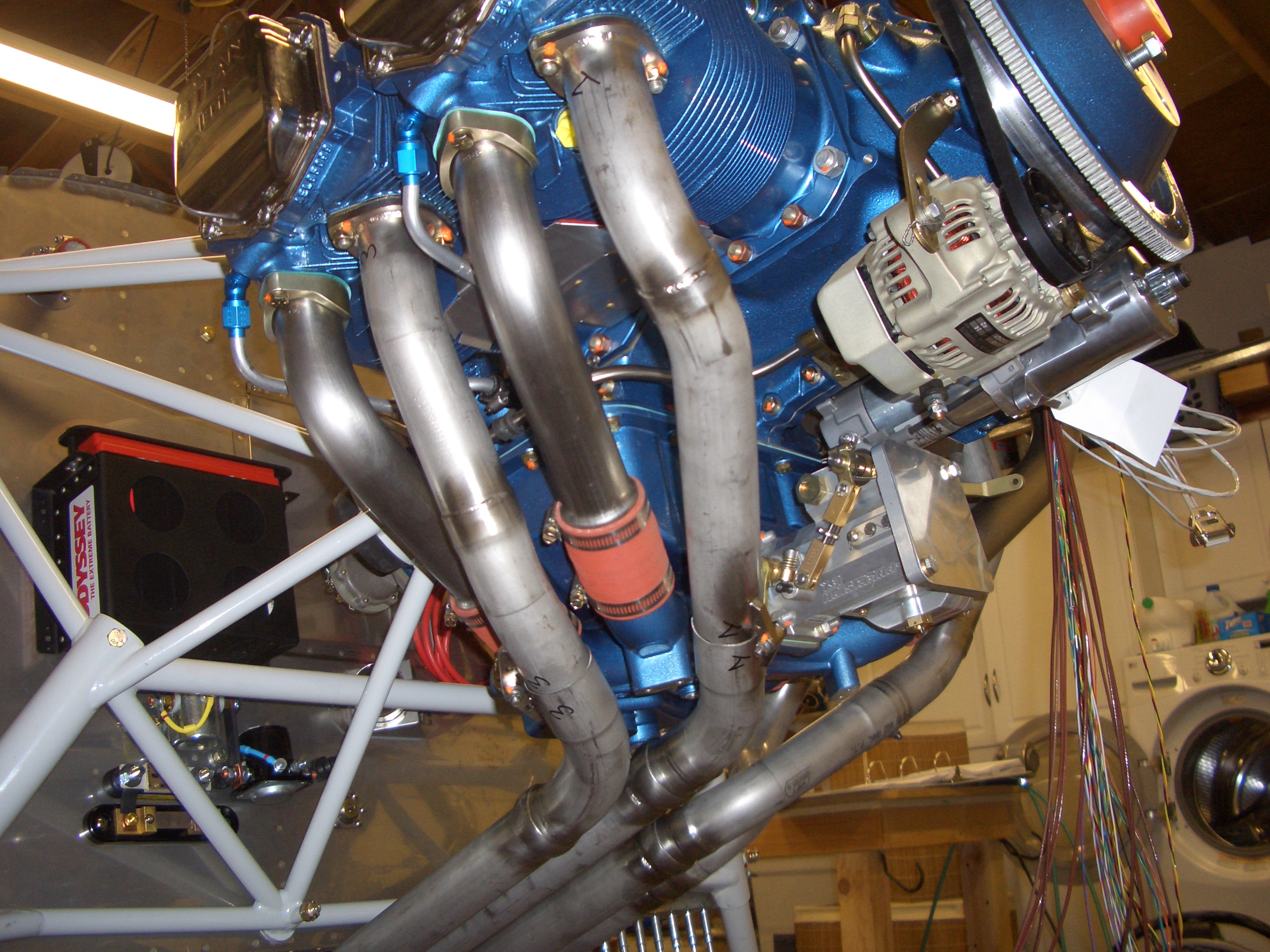
Here I’m getting the engine roughly in position.  It was definitely a little nerve-wracking to have $30k worth of engine hanging 3 feet off the concrete.  You can tell that the angle of the engine and the mount are still way off.  Since I don’t have a load tilter, it’s probably easiest to change the angle of the plane.  And yes, that is a garter hanging from the engine hoist (don’t ask).

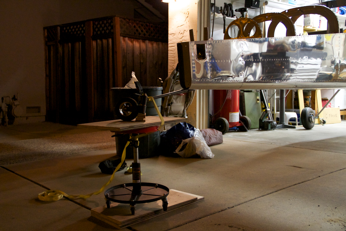
We propped the tail up on my adjustable shop stool.  I put some wood blocks under the tailwheel fork so that the wheel wouldn’t roll around.  The spring is strapped to the stool.  It looks precarious, but it’s actually pretty solid.

We’ve just about got the engine in place, but the tail is still too low.  It’s close enough that I can push it into alignment though.

I used a little hillbilly engineering and rigged a tie-down strap to one of the rafters.  I used this to lift the front of the engine enough that the bolt holes came into alignment.

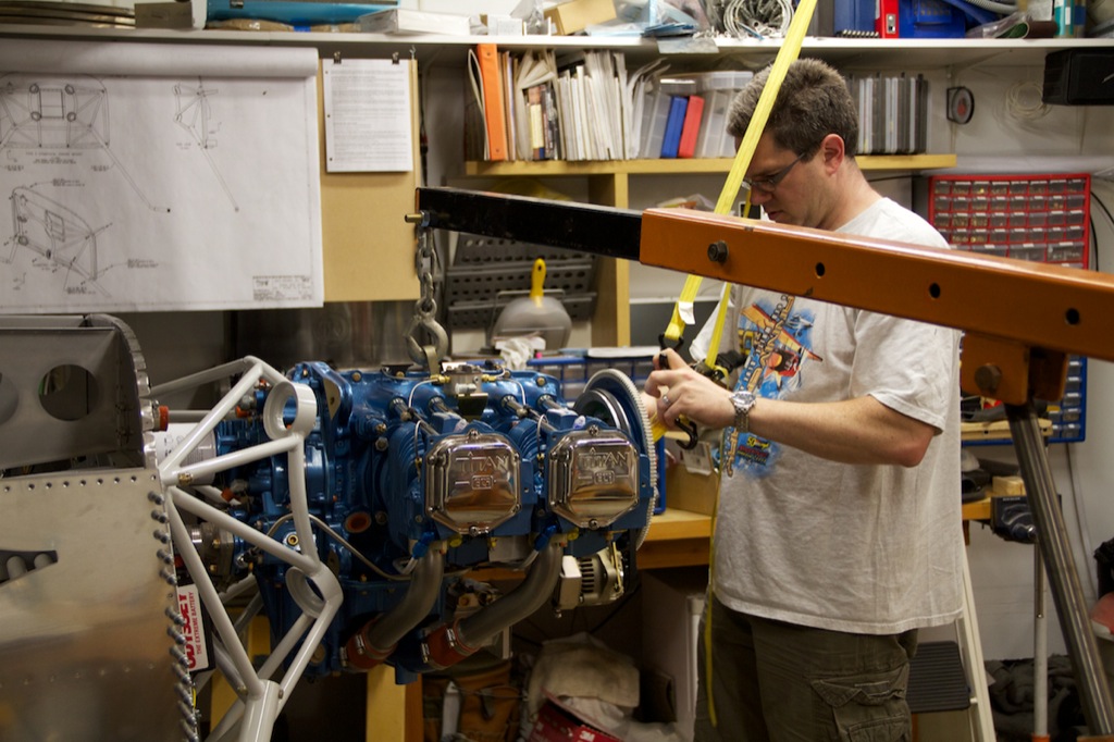
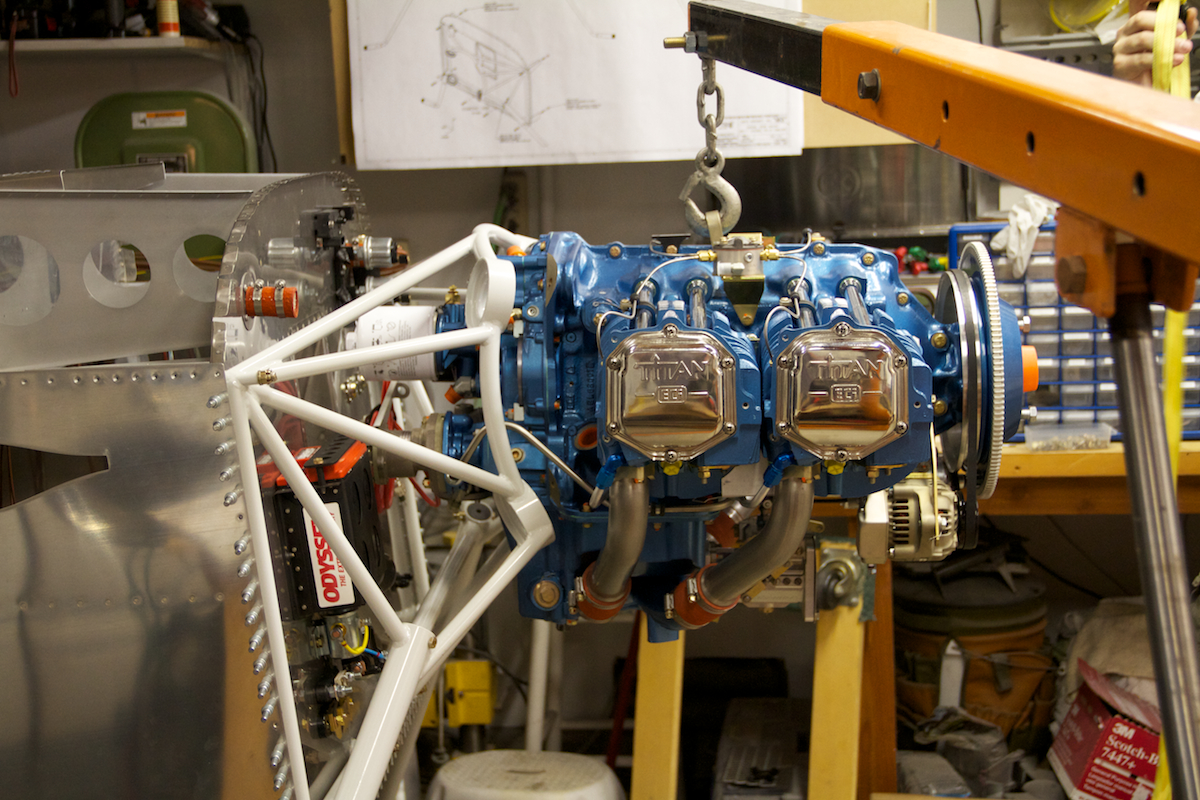
Here, we’ve got the top two engine mounts in place and are positioning the engine and plane to get the holes in close alignment.

Here I’m installing the top two bolts.  These went in pretty quickly and with only a little persuasion.

The third bolt (lower right) was not too much harder and went in with a little wiggling of the engine.  The fourth bolt (lower left) was a little more of a pain.  I had to tighten the other three bolts fairly tight and still needed to use a bullet to move the rubber mount a little when getting it in.

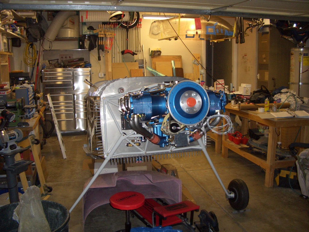
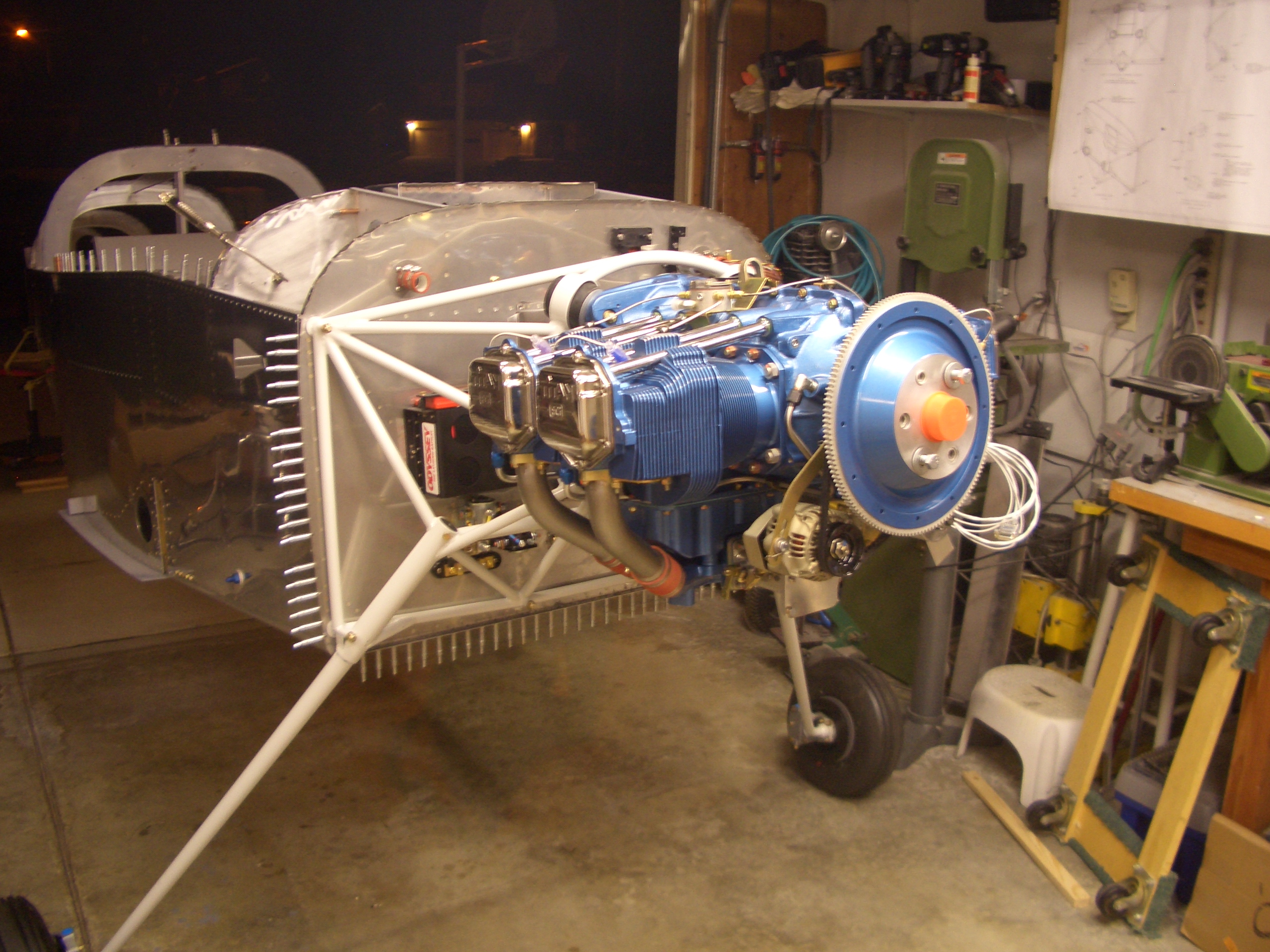
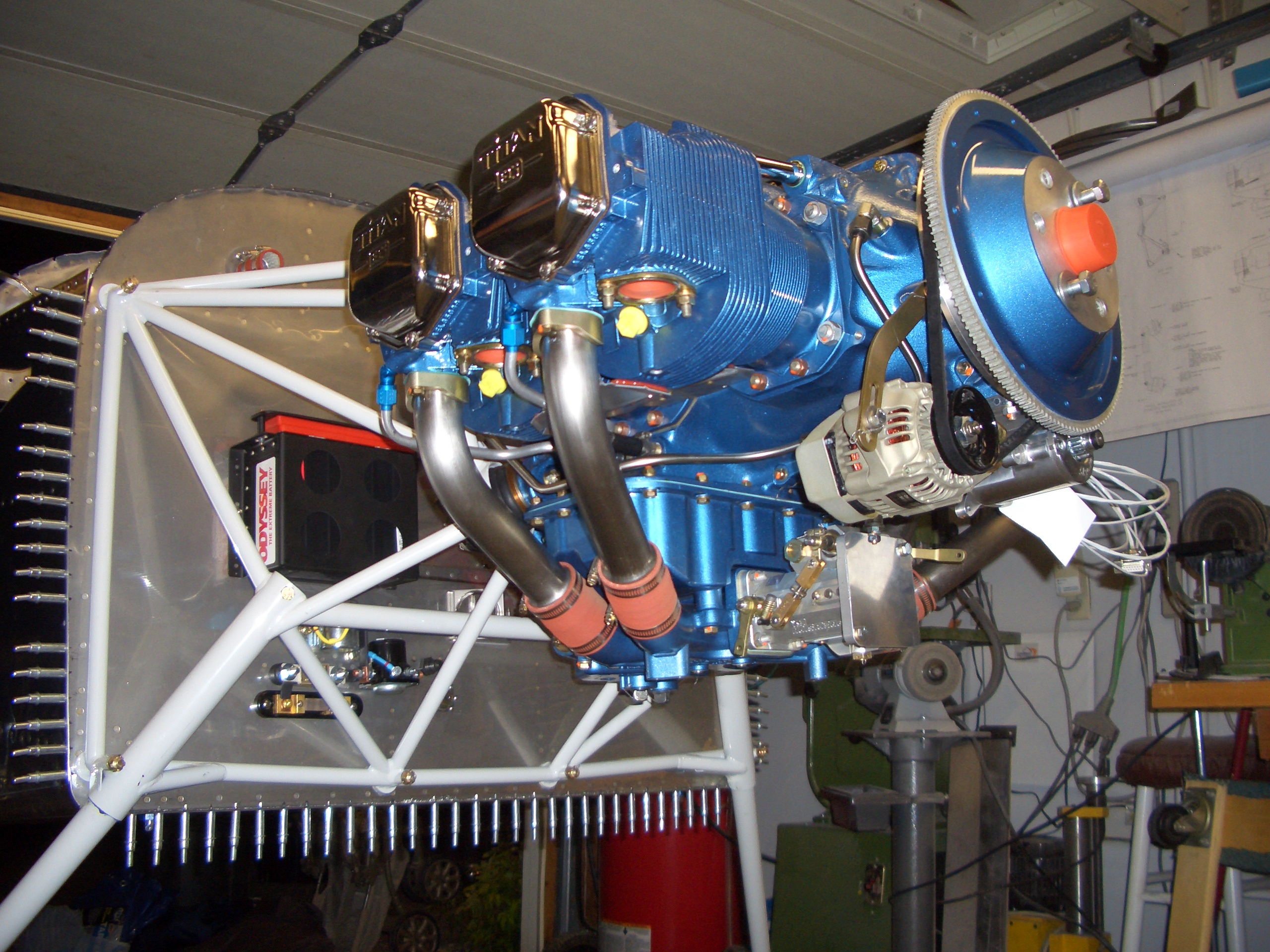
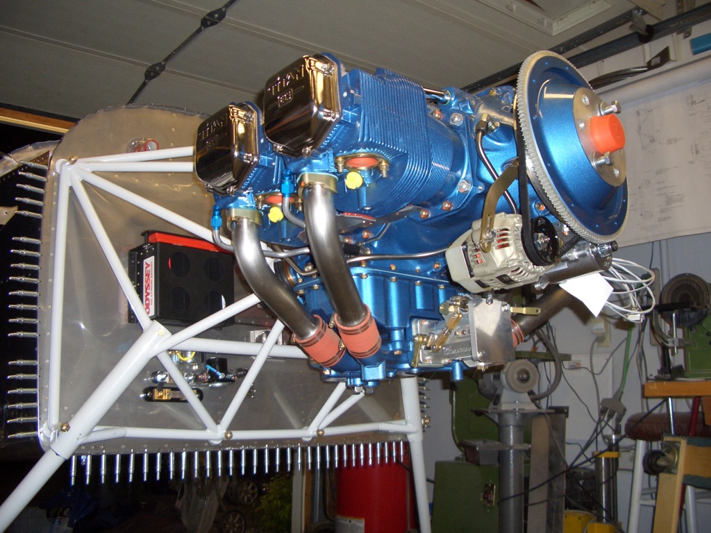
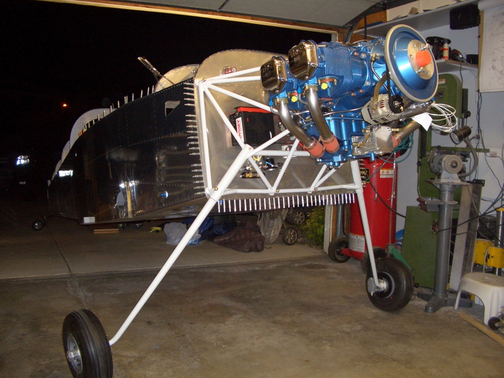
I still need to torque all the bolts, but the engine is hung!  The tail is still up on the stool in this shot which is why the plane looks fairly level.

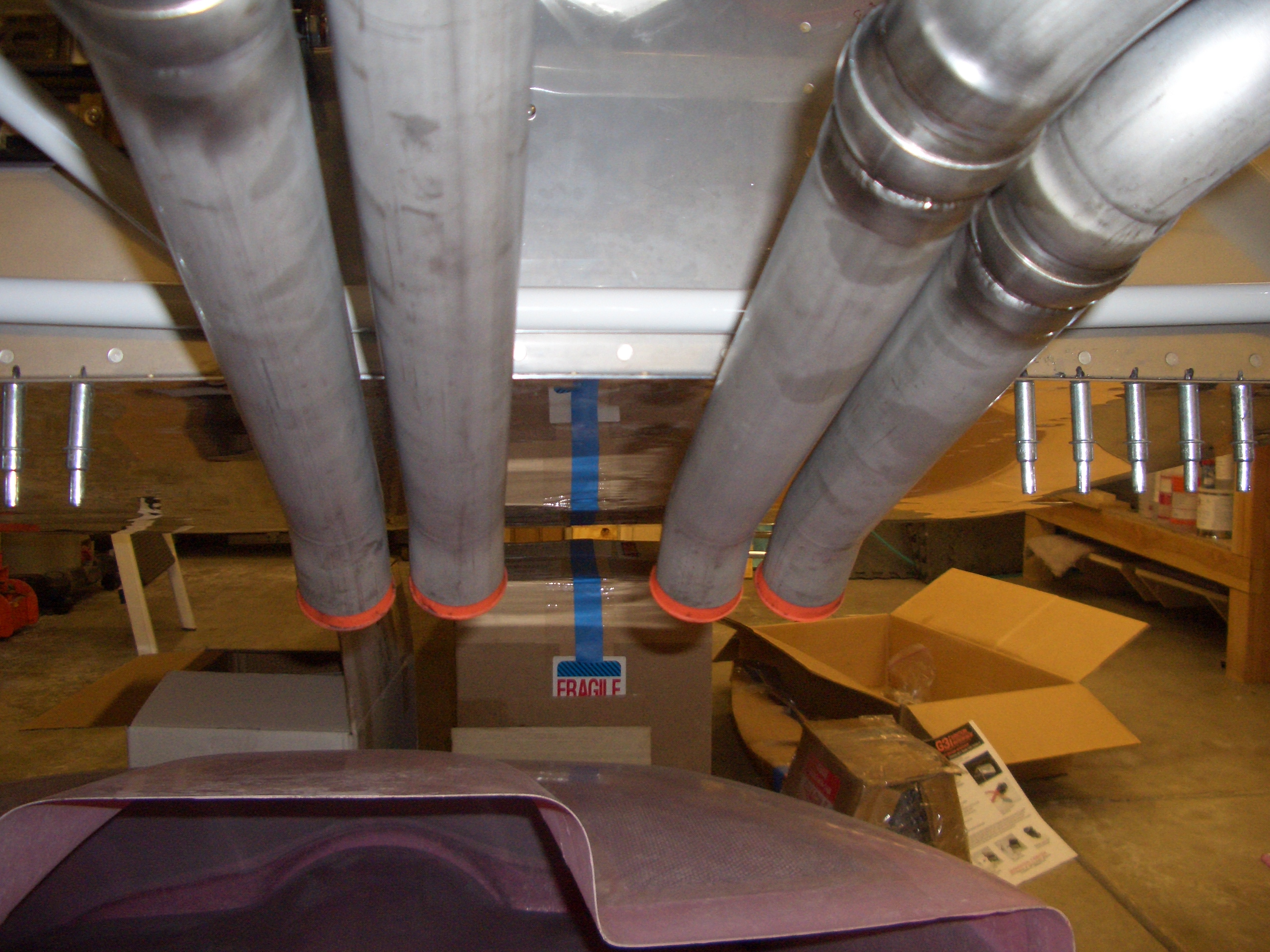
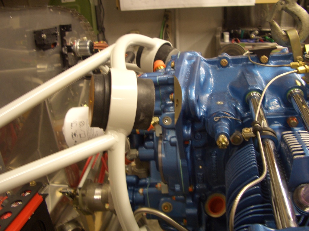
Here’s a shot from the bottom for no good reason.

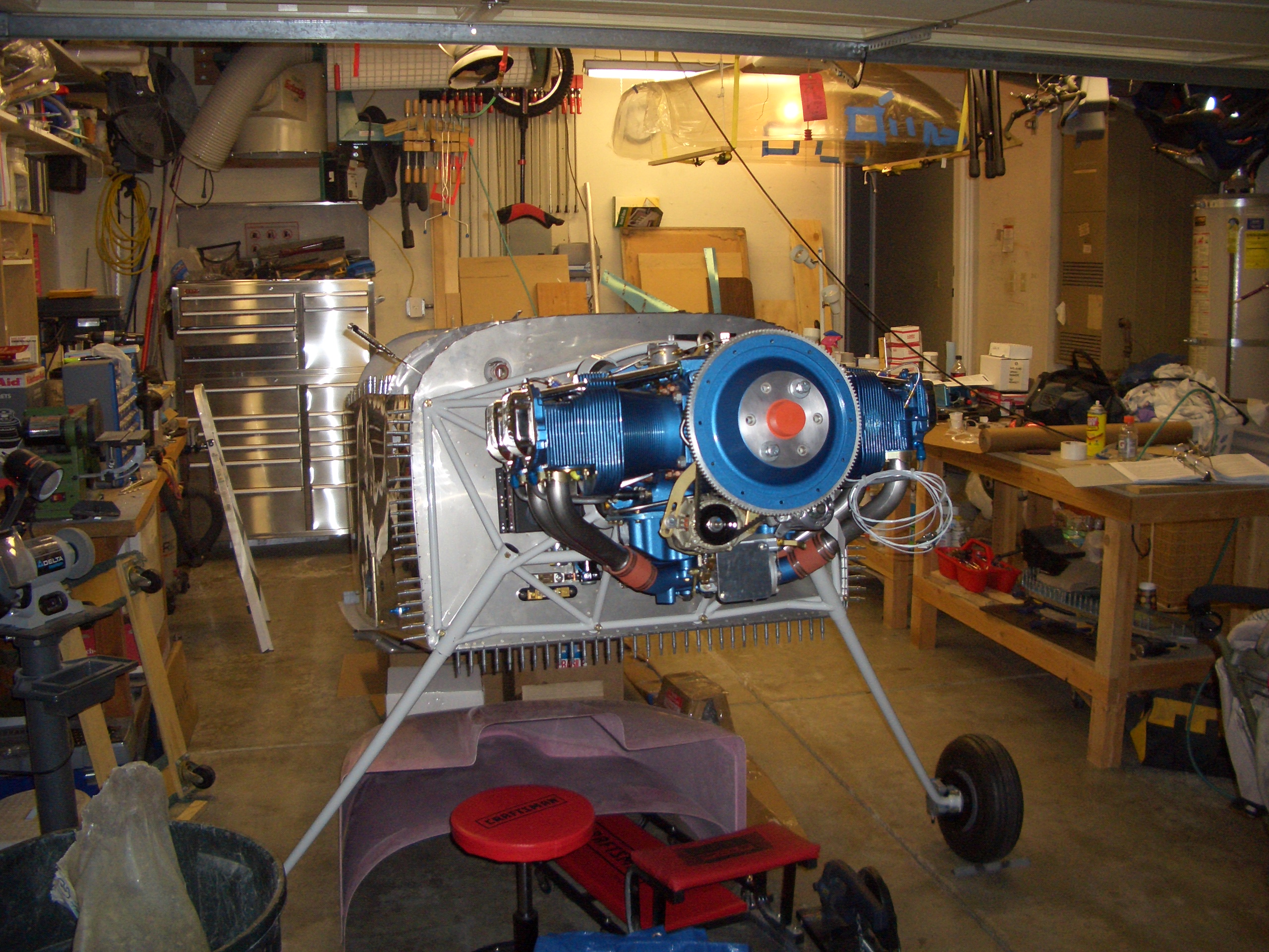
Now the tail is back on the ground, so this is the attitude the plane will normally be in.

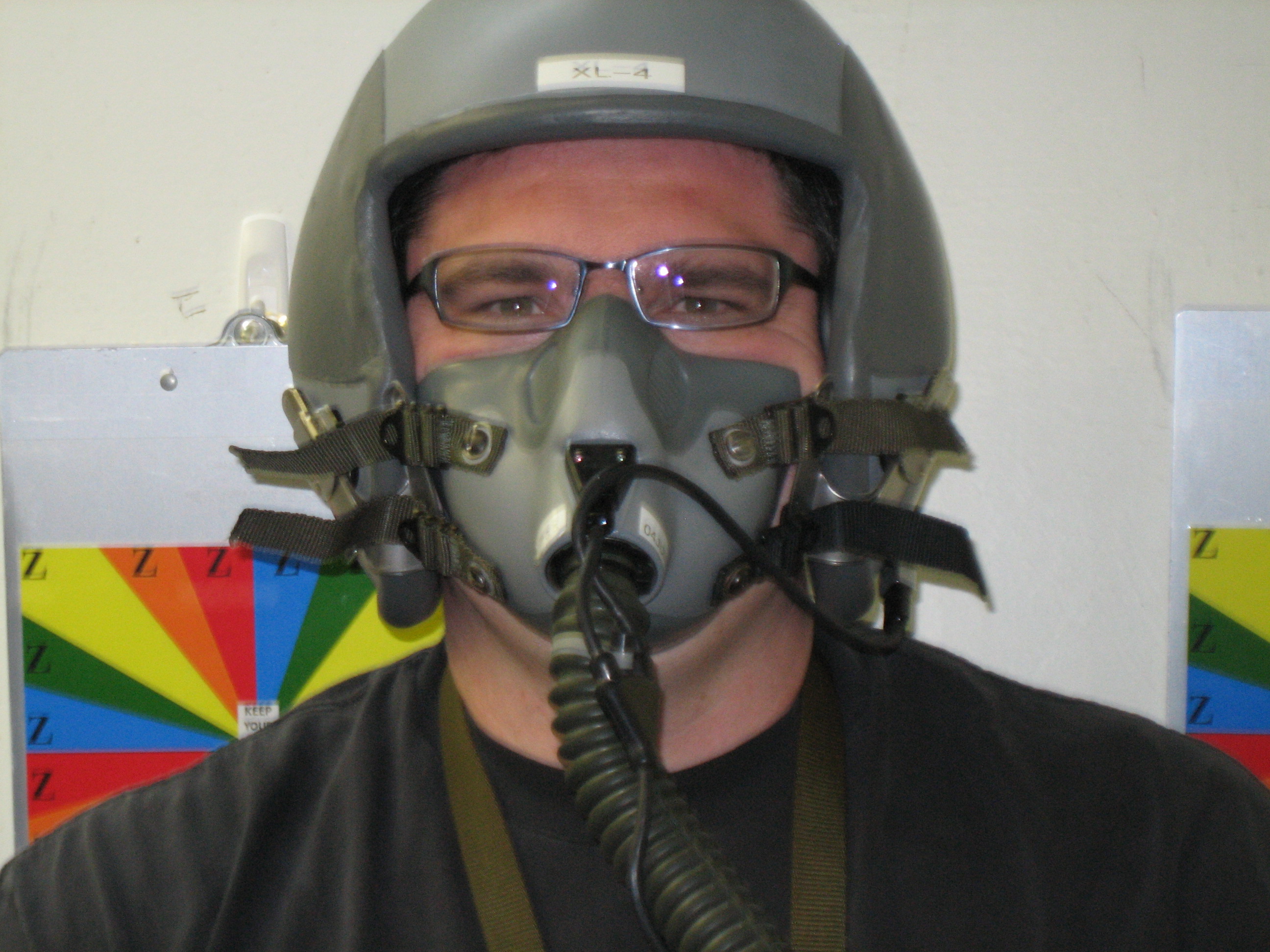
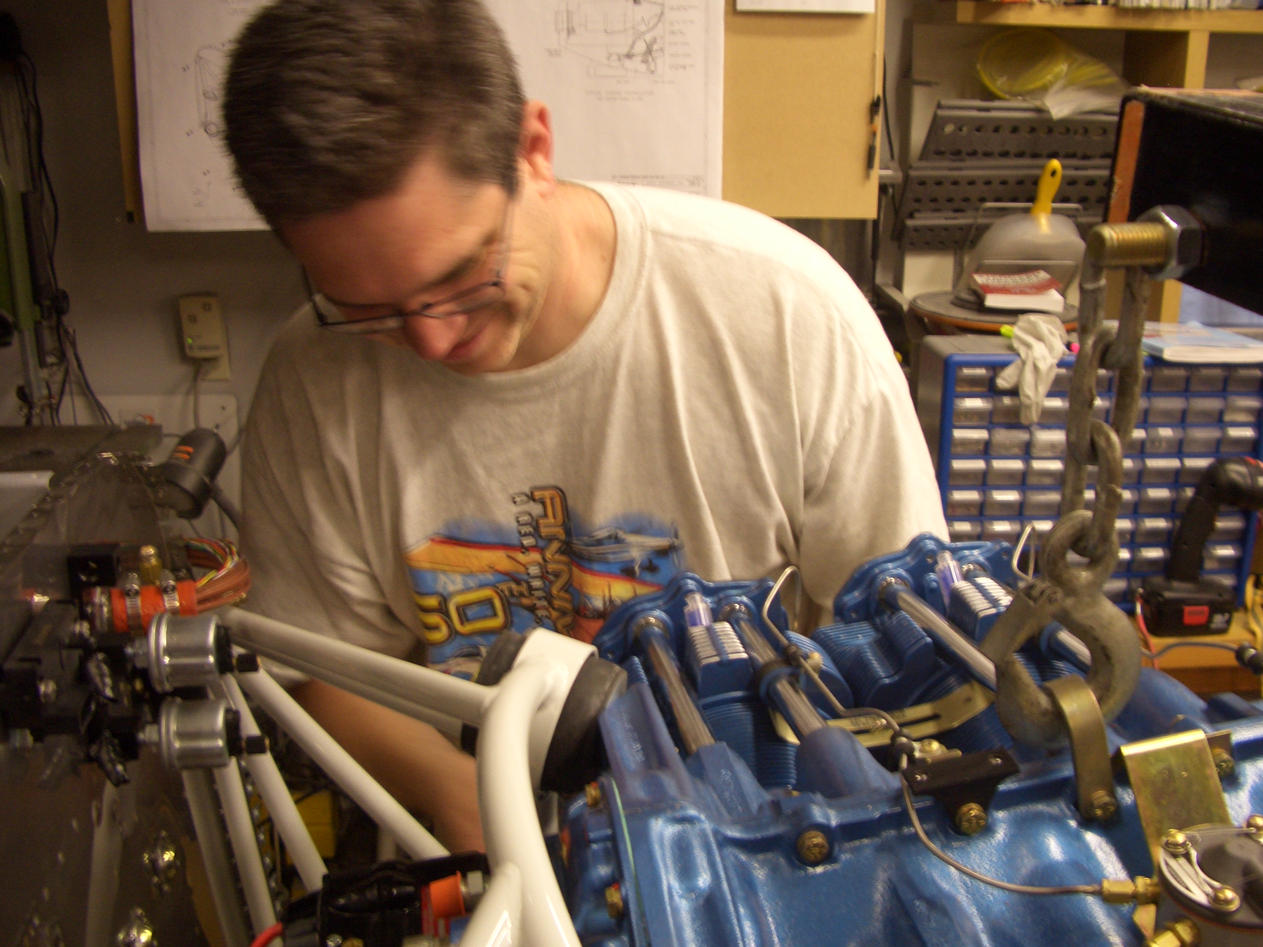
Here I am posing with my newly hung engine.

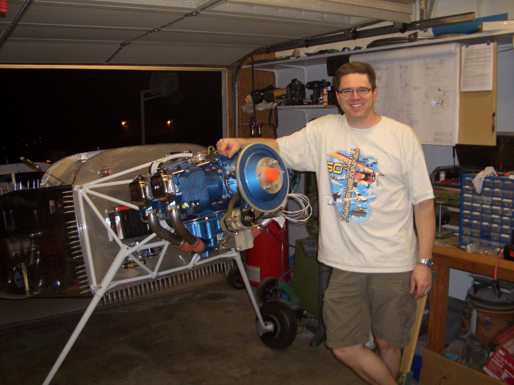
The plane is now back in its spot in the garage.  This has been a long day, and I’m beat, but I’m totally stoked to have hit this milestone.

Mounted Exhaust

Since I have the engine mounted, I decided to go ahead and mount the exhaust (mostly in an effort to get more boxes off of the floor that are taking up space.  First up, I needed to squeeze the rivets in the bottom center of the firewall where the cowl outlet sits (you can see the cowl at the bottom of the picture).  The outer portions of the bottom edge of the firewall will attach the lower edge of the cowl.

Here’s the cowl in place with all bolts torqued.  As I’ve mentioned before, I went with the Vetterman four pipe exhaust.

Here is what the exhaust looks like where it exits the cowl.  I like the look of this so much better than the crossover exhaust.  The only issue I ran into is that the four pipes stick out of the cowl slightly different amounts (over 1/2″ difference between the shortest and longest pipes).  I’ve emailed Larry Vetterman to see why this might be the case.

I went ahead and installed the oil filler neck and safety wired it to the case.

Checkoway had one of his hose clamps loosen in flight and recommended safety wiring them to prevent that.  Here, I’ve safety wired the intake tube hose clamps.

I also safety wired the hose clamps on the cylinder oil return lines.

CHT sensors and lower plugs

I didn’t have much time tonight, but I wanted to get something done on the plane.  I’m trying to get all of the fixed items installed to the engine (those where I have no choice of location) before installing those items where I do have a choice.  I used some anti-seize compound and installed the CHT sensors in the port on the bottom of each cylinder.  The wires are just hanging for now until I determine for sure where the Dynon EMS box will be mounted.

I also installed the lower plugs (again with anti-seize) since I wanted to make sure the EGT probes won’t interfere.

Battery Positive Cable, Mixture Bellcrank

I got my battery cable and terminals from SteinAir.  I’m going with #2 Tefzel cable even though it’s very hard to bend.  I considered both welding cable (recommended by Bob Nuckolls in his AeroElectric Connection book) and CCA Fatwire sold by Perihelion Designs.  Both are far more flexible, but the insulation is only good to 105ºC at best vs. Tefzel which is good to 150ºC.  It will be a little more difficult to run, and there is a slight weight penalty compared to the more common #4 wire, but this should be made up for by lower cranking wire loses which should result in a faster spinning starter and an easier to start engine.

I crimped one of the connectors on a piece of wire using an impact crimper I picked up from a welding supply company.  The crimps aren’t the prettiest, but they’re very secure.

I then slipped a piece of heat-shrink tubing over the joint to provide a little bit of wire support.

I then bent the end of the terminal over 90º.

This terminal is attached to the input side of the battery contactor.  The other end will attach to the positive terminal on the battery.  I need to order so more silicone nipples before attaching the other end for good.

I wanted to see if the mixture bellcrank would fit on the superior sump.  It’s supposed to install under these two bolts, but this plug is in the way.

After cutting the safety wire and removing the plug, here’s the hole that’s left.

The bracket now fits over the boss in the sump, but unfortunately the holes are still off by almost 1/4″

I deepened the notch in the bracket enough that it could be bolted in place.  Notice that the hole is still there, and this bracket will prevent the original plug from being reinstalled.  I’ll have to order an AN932-5 plug to install here instead.  That is a hex drive plug that will install flush with the surface of the case.

Here is the mixture bellcrank in the most rich setting I can get.  Unfortunately, the mixture lever is interfering with the starter.  I’ll call Precision Airmotive to see if they can send me an alternate mixture lever.

Here is the mixture bellcrank in the most lean position.  I can hit the idle cutoff stop without any problems.

Finally, I spent a little time trying to figure out how to secure the throttle cable.  The Superior sump doesn’t have threaded ports in the bottom in the same location as a standard Lycoming sump, so the bracket from Van’s won’t fit.  I’ll probably have to fabricate a custom steel bracket for the throttle cable.

Swapped Rocker Cover Gaskets

I called Precision Airmotive this morning, and they have a shorter offset mixture arm (1 5/8″ vs. 2″) that should work perfectly for me.  This should eliminate the interference with the starter and allow me to hit both stops on the mixture arm.  With the longer lever, I could hit one stop or the other, but not both due to the short throw of the control cables.

I also called around for a bit trying to find an AN932-5 plug, but couldn’t find anybody who stocked them.  I ended up ordering an AN932-5D plug instead which will work fine.

I spent most of the night cleaning up the garage, but I did swap out the rocker arm cover gaskets.  You can see the old cork gasket on the left and the new silicone gasket on the right.  Surprisingly, I already found an oil leak from the old cork gasket, so I’m glad I replaced these.