Prepped Firewall for Riveting

My mom is in town, so I got her help dimpling the firewall.  I was a little worried that the DRDT-2 dimpler wouldn’t make as crisp of a dimple in the stainless (though I didn’t even try to see if this fear was warranted).  My buddy Andre has a couple of the traditional Avery style dimplers, so I borrowed one to dimple the firewall.

As you can see, the dimples are perfectly crisp and the material around the dimple is perfectly flat.

I also machine countersunk about half of the holes in the stiffeners before having to call it a day.  Hopefully I can finish these up, prime them and rivet the firewall together in the next couple of days.

Riveted Firewall

My step-father Curtis was in town and gave me a hand prepping the firewall components for priming and helped me back-rivet everything in place.  We had a little problem with one of the corners because the firewall wasn’t sitting flat on the back rivet plate.  I drilled the problem rivets out though and everything looks great now.  Like many other builders, I had to go up in length on some of the rivets to get a sufficiently large shop head (though I don’t think it would have mattered to just use the size called out for in the plans).

Started on Center Section

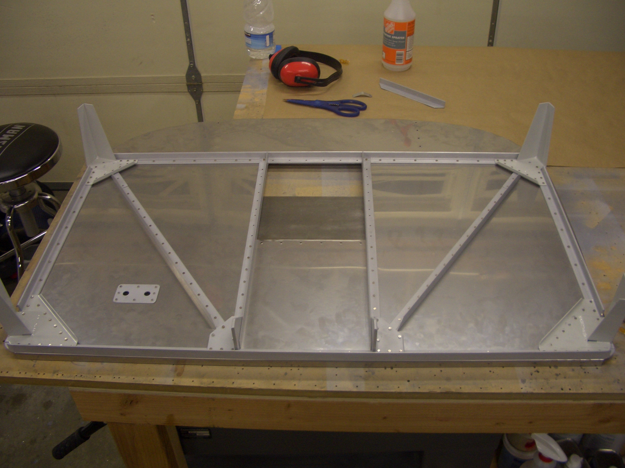
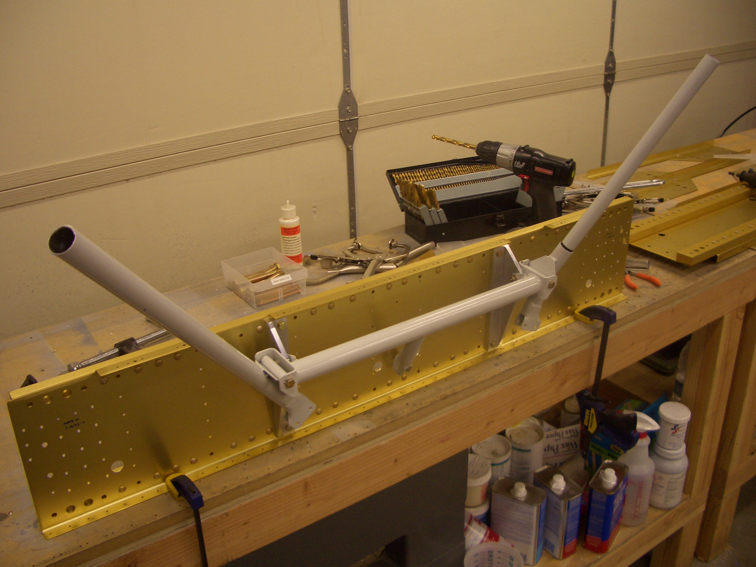
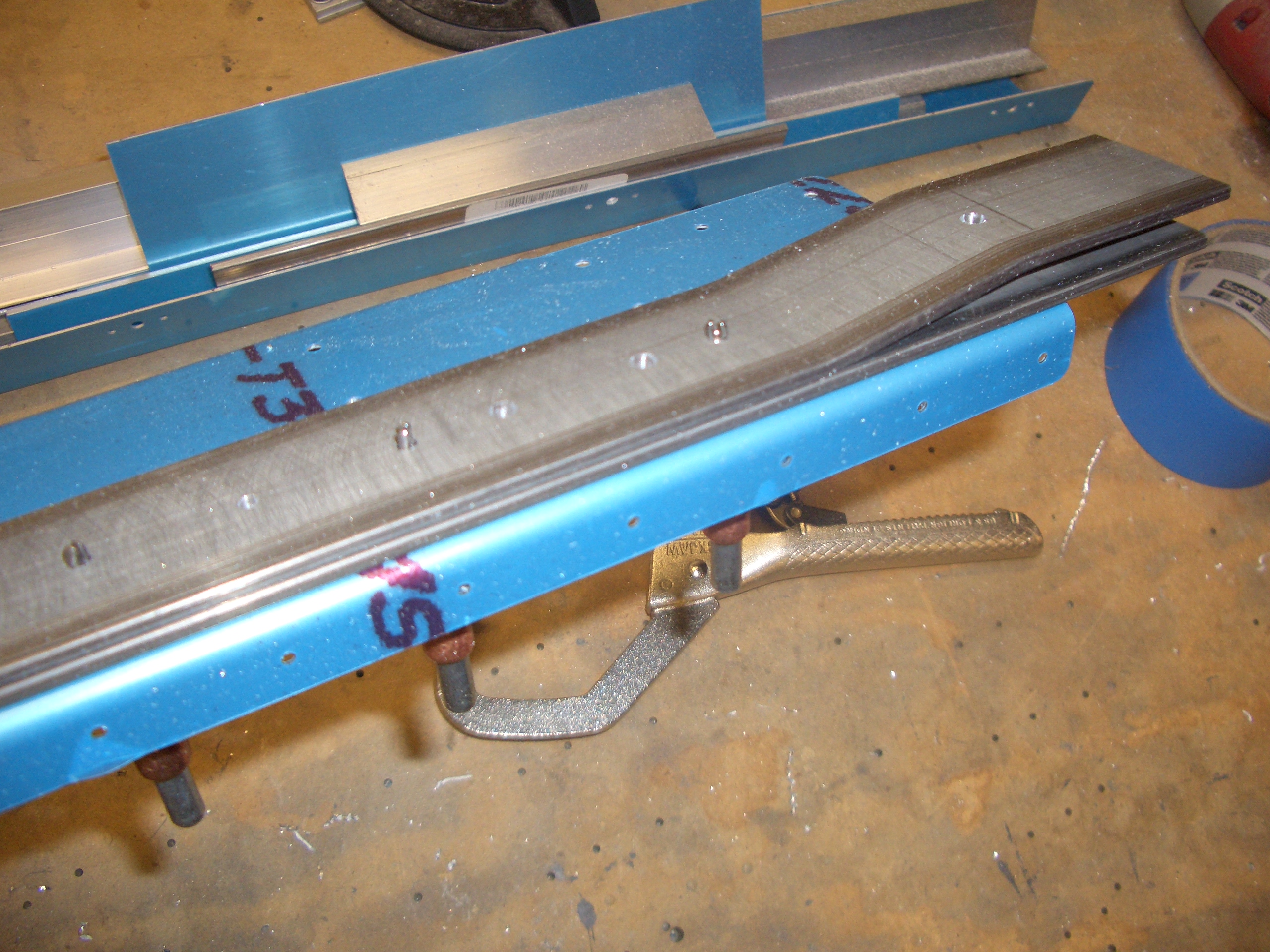
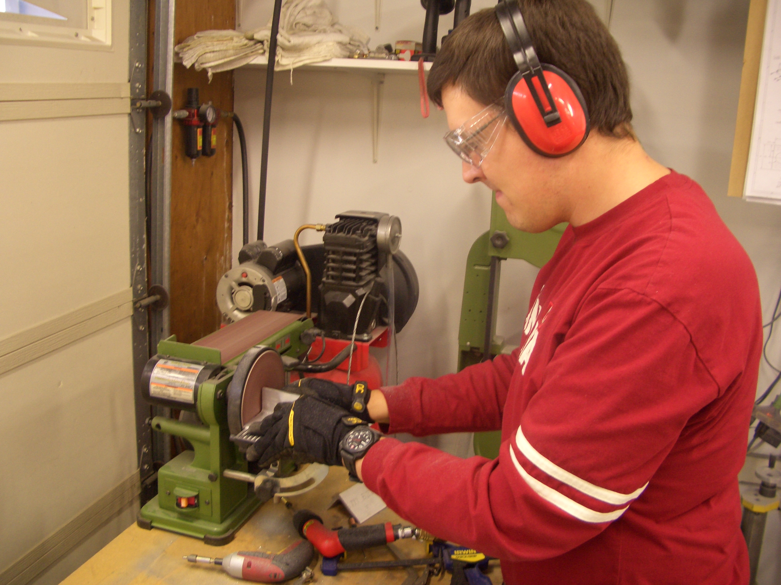
Now that the firewall is out of the way, I got started on the center section.  First up is to enlarge the holes in the side supports to allow the rudder cables to pass through.  These are drilled out to 5/8″ for an SB625-7 snap bushing.

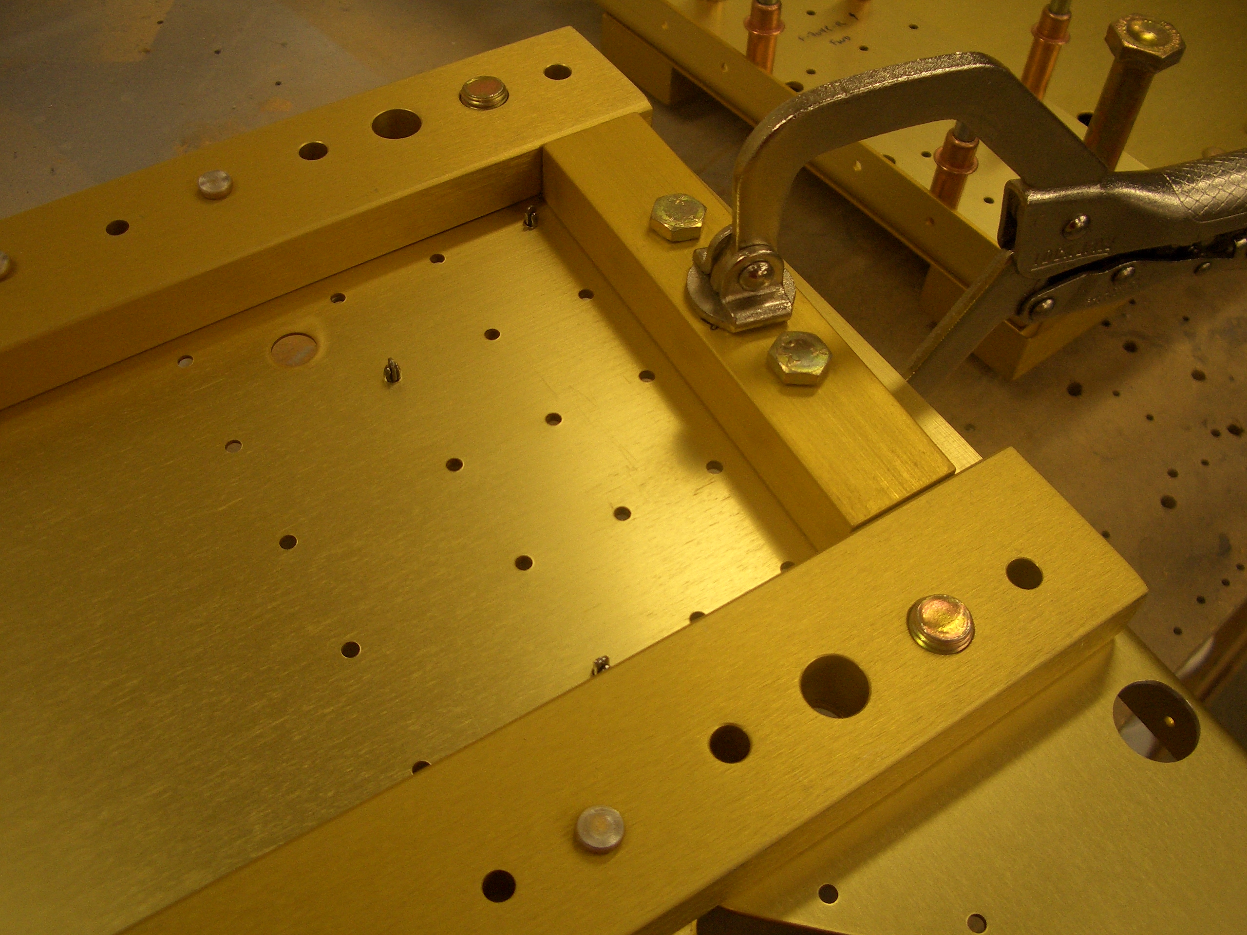
The side supports are then positioned using a couple of close tolerance bolts so that the rivet holes can be precisely match drilled.  These bolts are seriously snug.  Even with some lubricating oil, I had to push these rather firmly to get them through the holes.

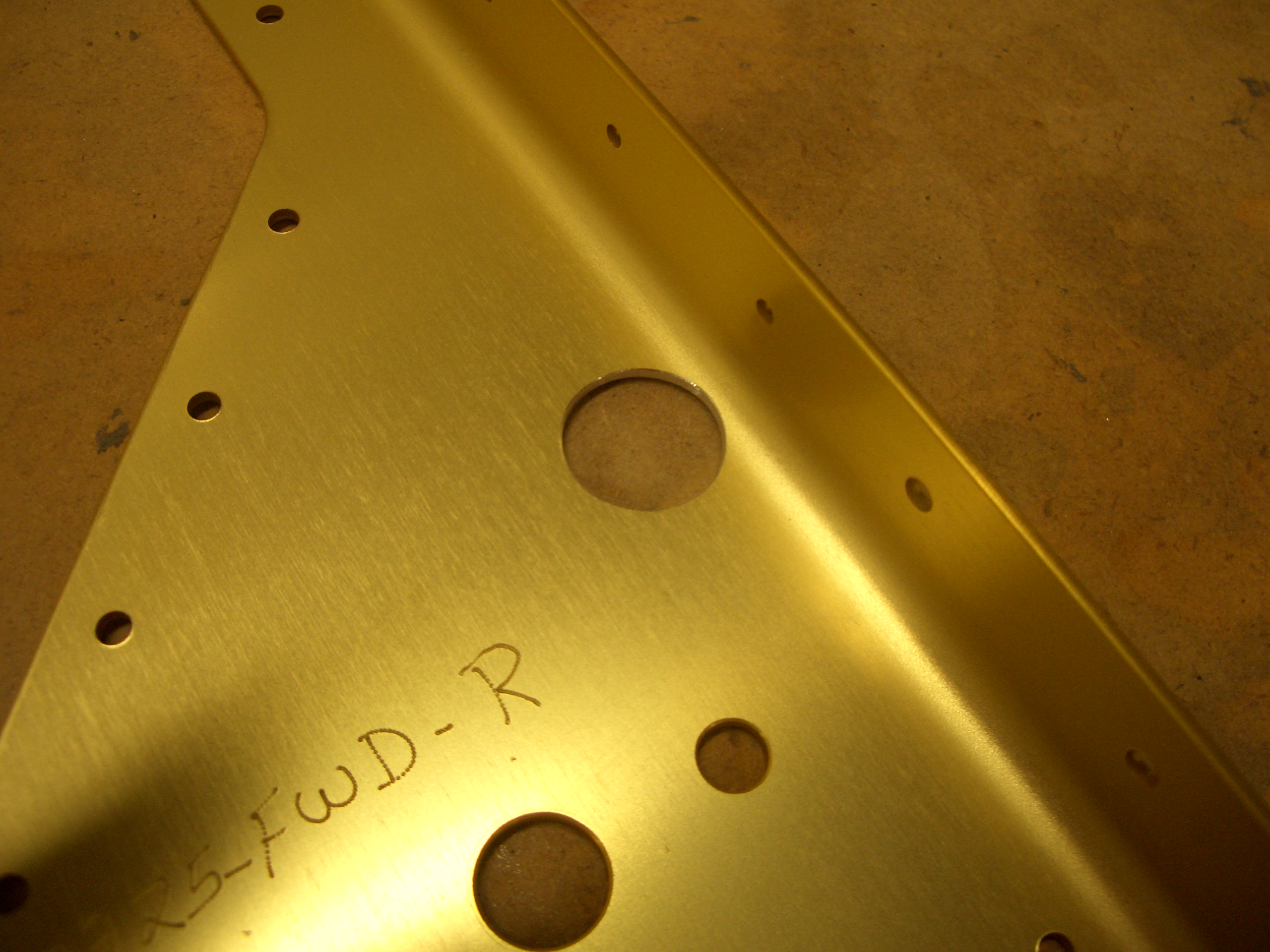
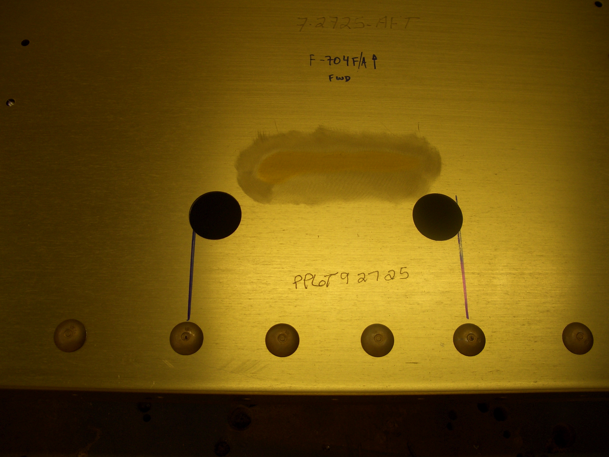
I also noticed something odd when laying out all of the pieces.  Van’s apparently mismarked the forward and after center sections (the aft section was marked fwd and vice versa).  This may have just been a marking error, but if the center section was flipped end for end when the wing spars were match drilled, then the close tolerance bolt holes may not line up precisely when the wings are mated.  I’ll call Van’s on Monday to see if they think this is an issue.  Hopefully their drilling jig won’t let this sort of mistake happen.

Update: I spoke with Ken at Van’s and he’s about 99% sure this is simply a marking mistake.  He didn’t know if their drilling jig would let them drill the center section backward, but said that if I wanted to be 100% sure, I could simply install the center section onto each wing using the close tolerance bolts to see if the holes lined up.

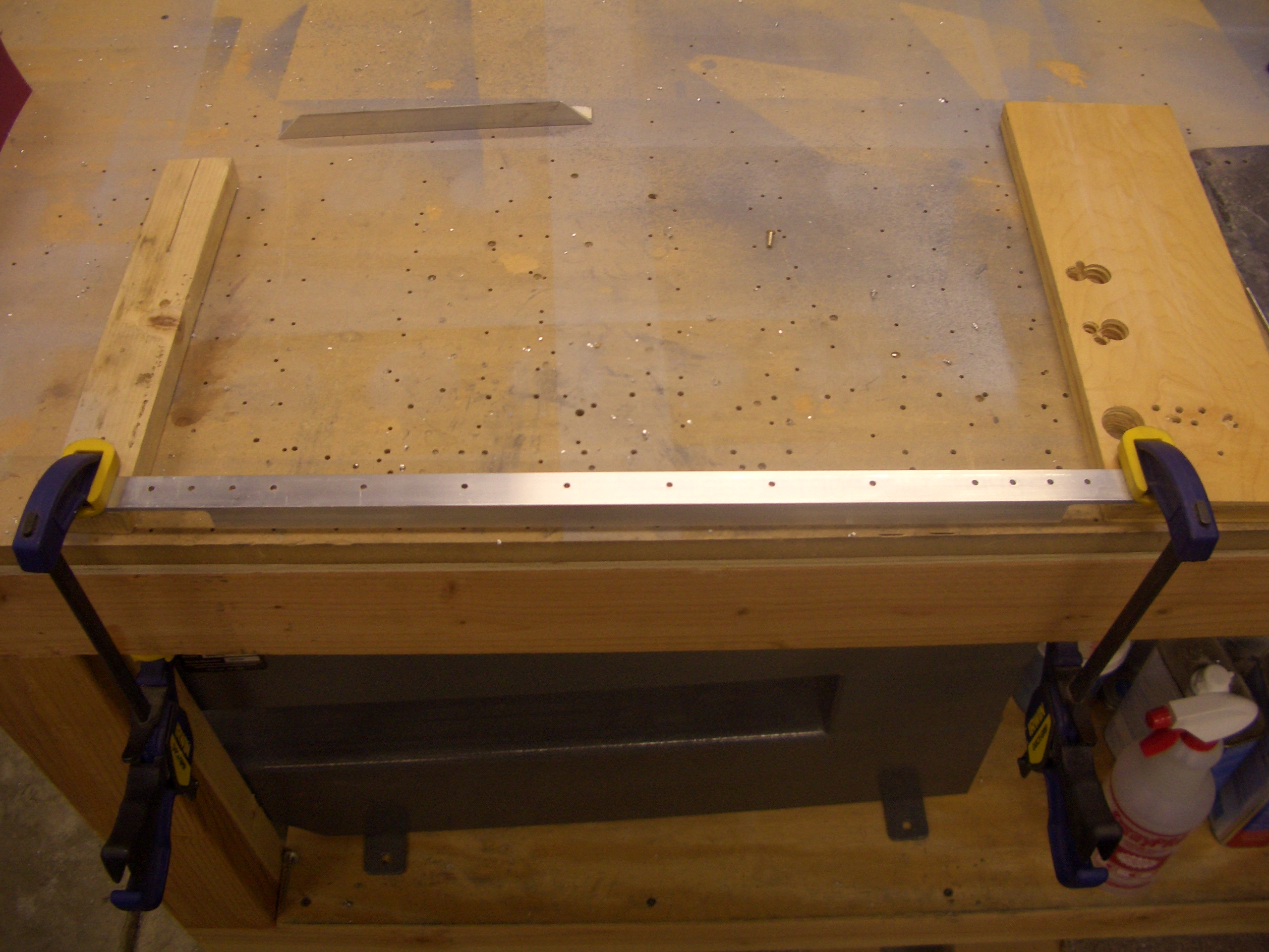
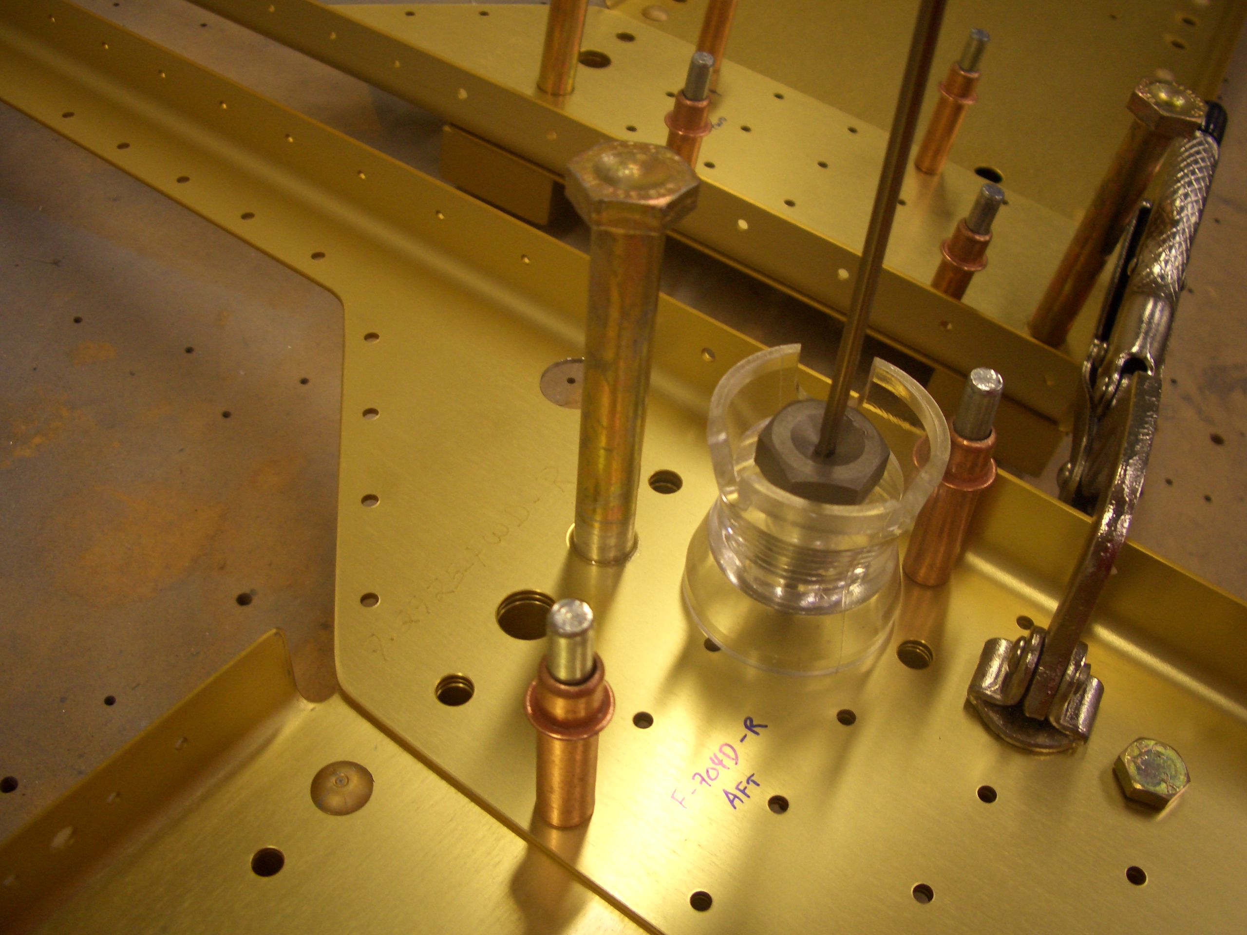
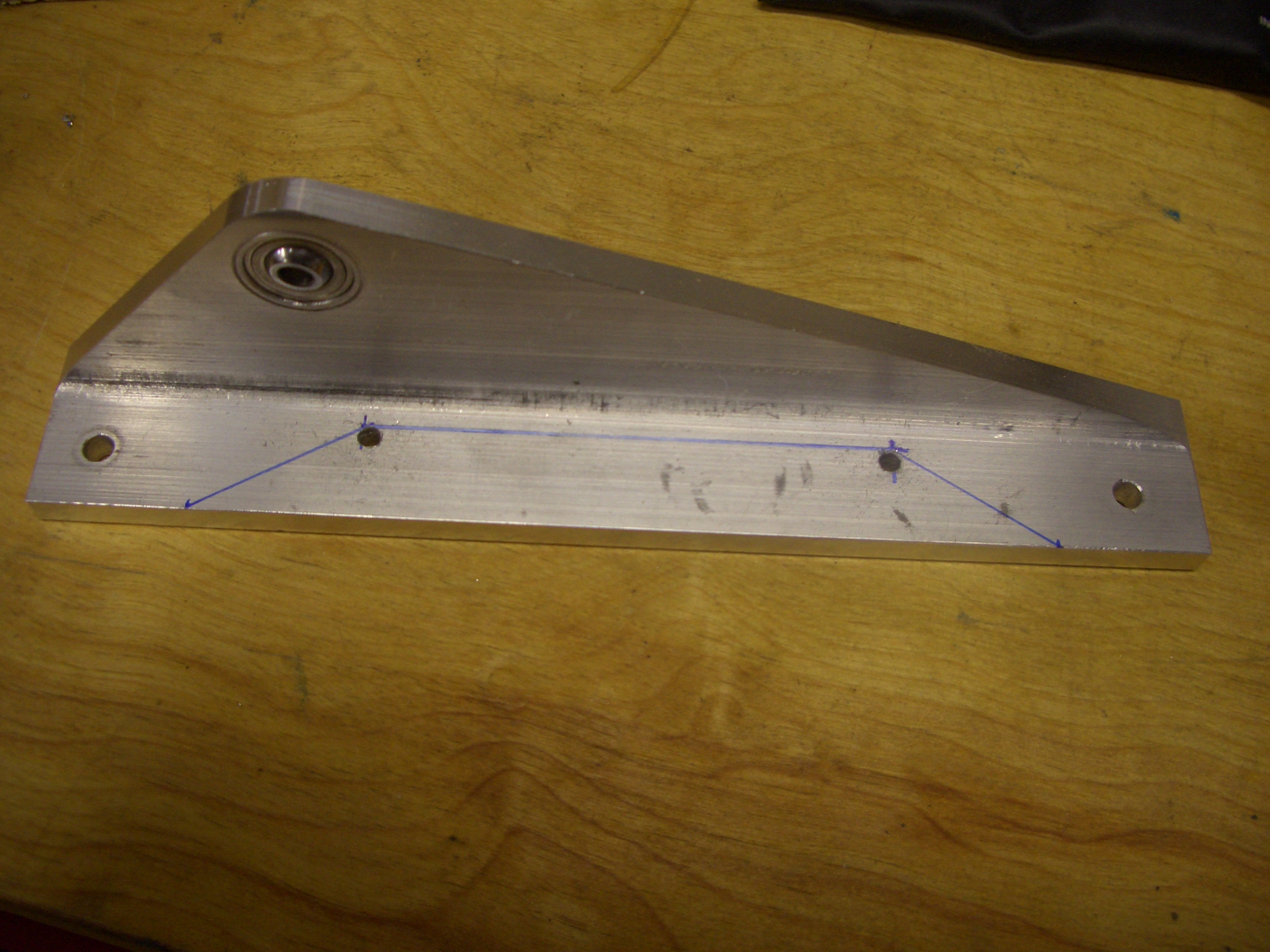
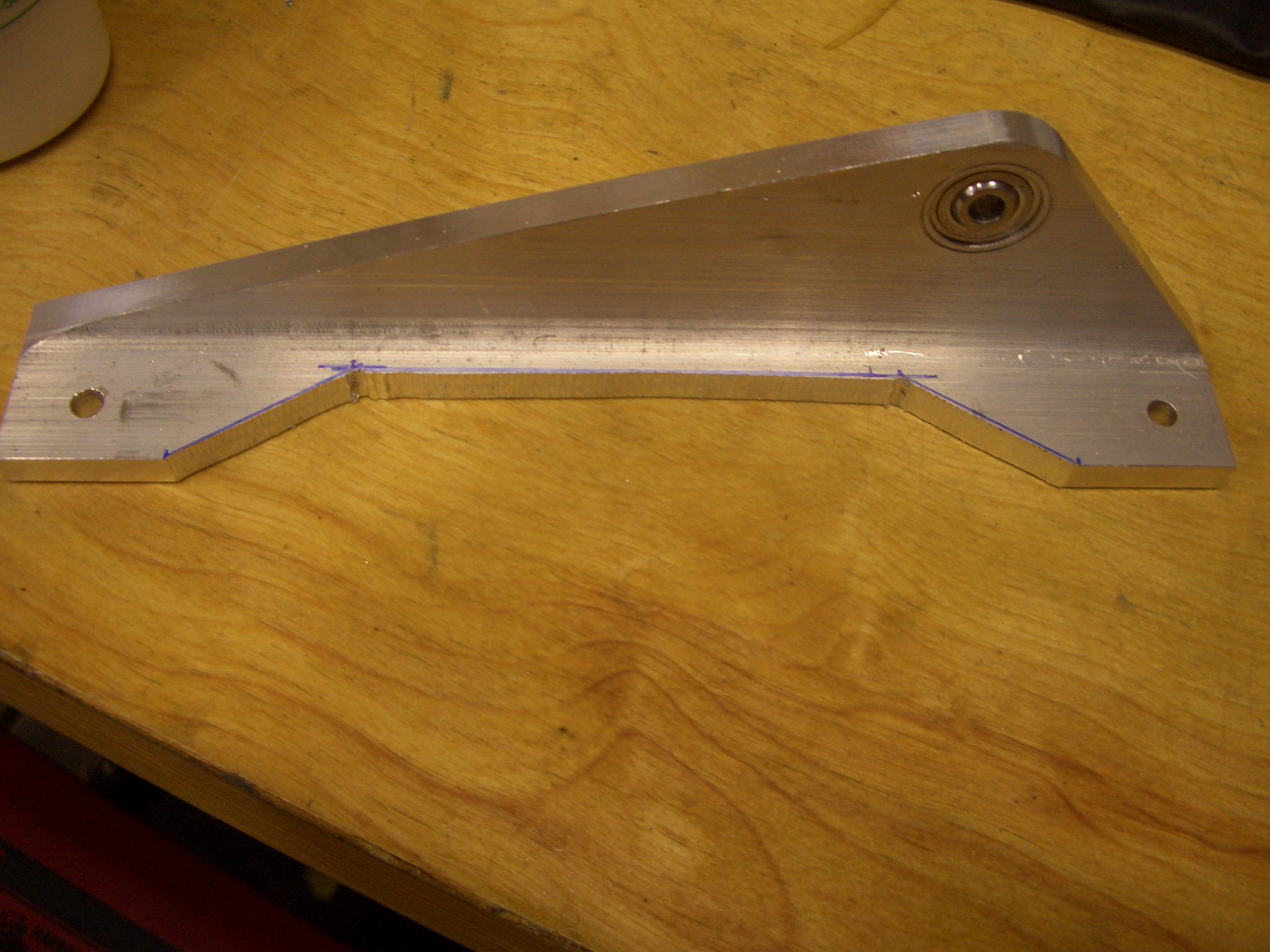
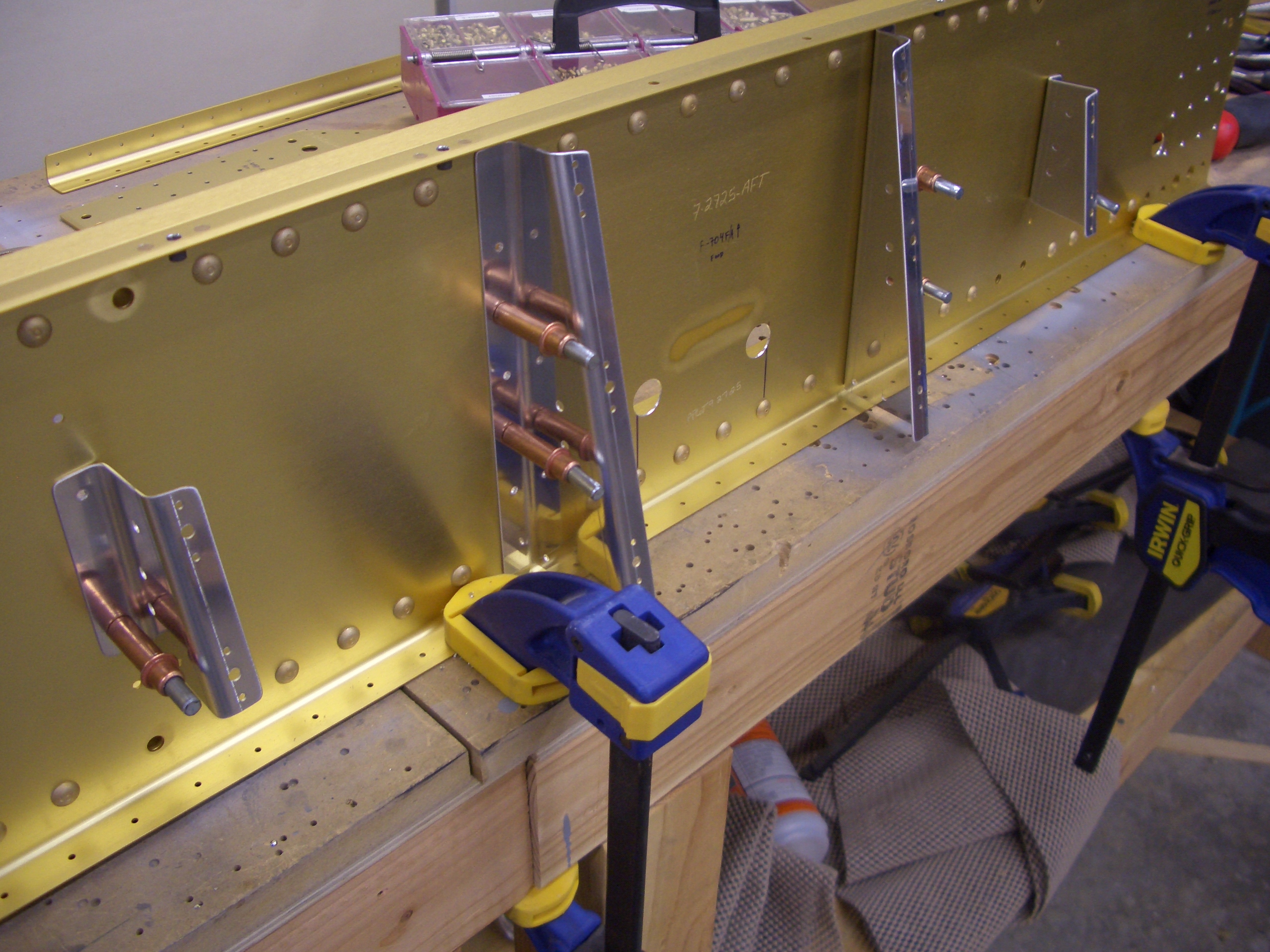
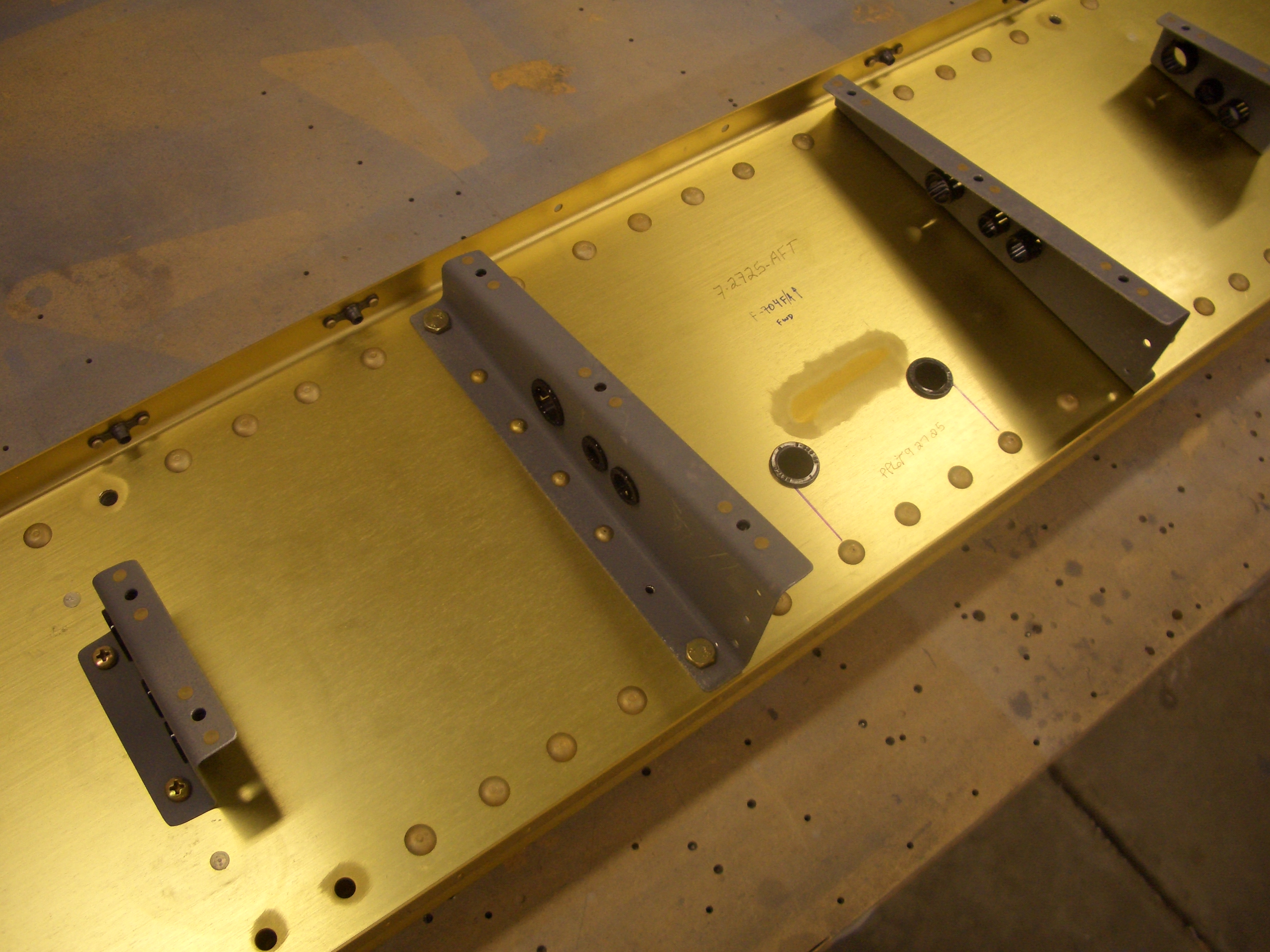
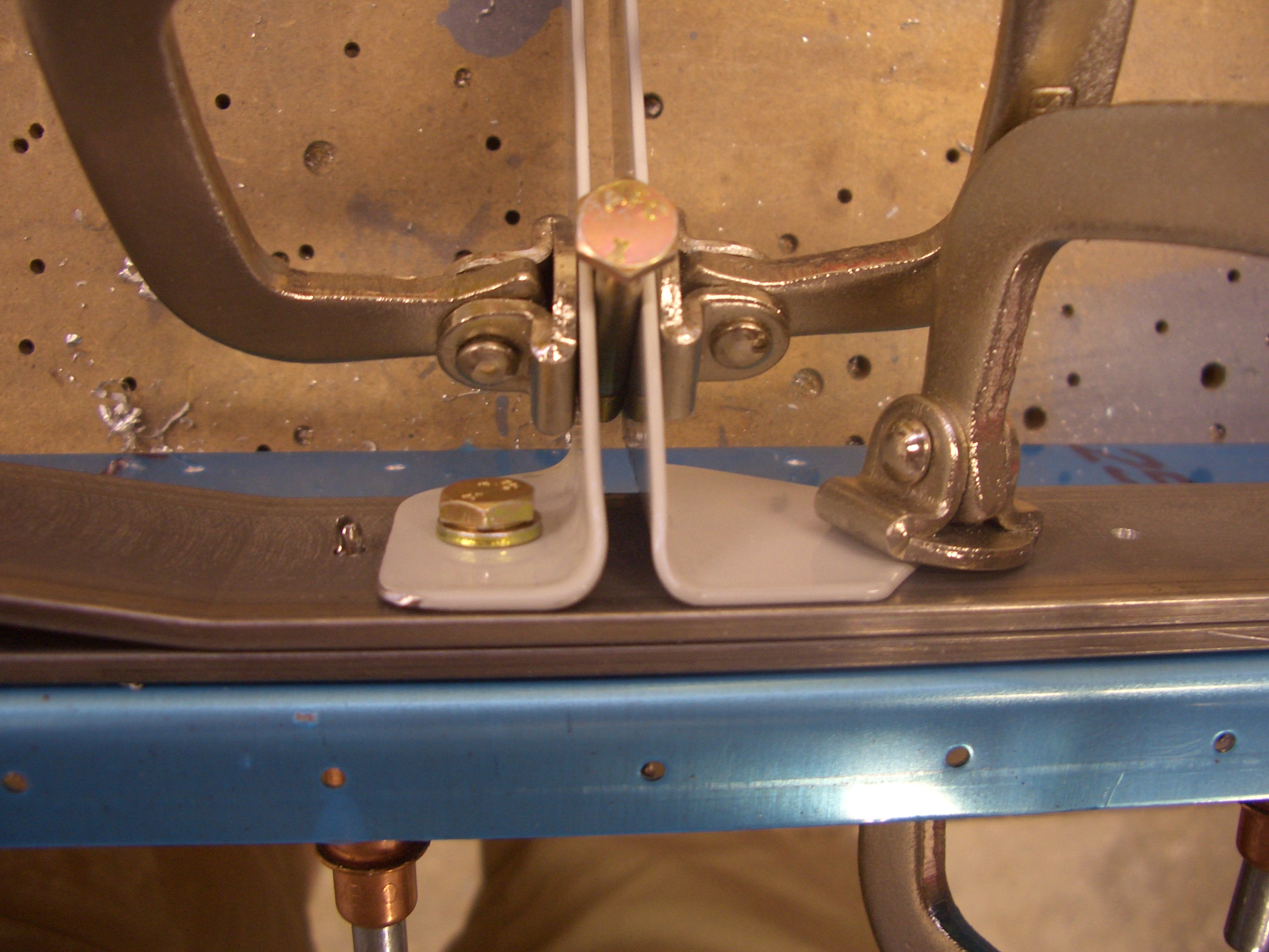
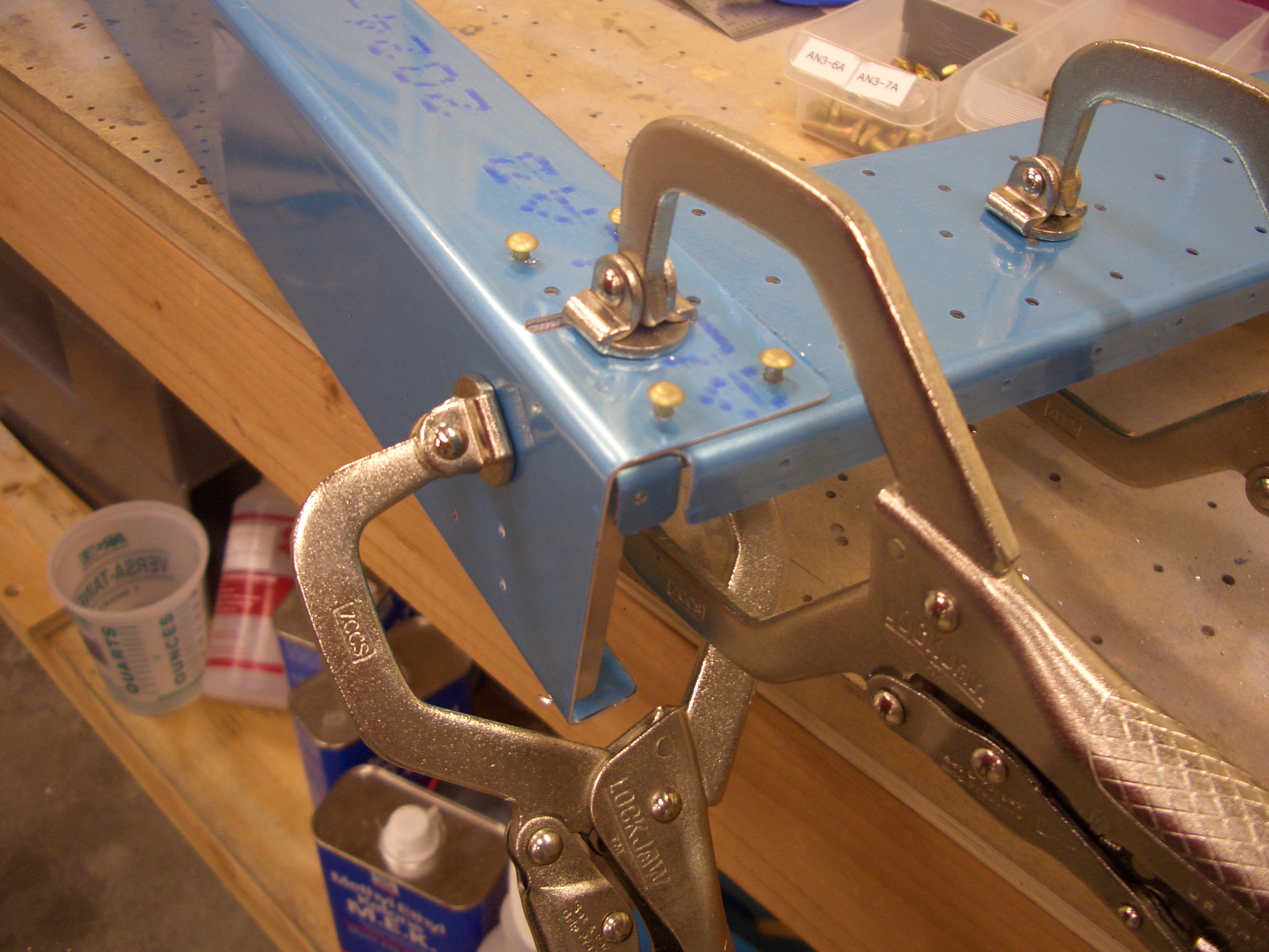
The aft center section needs some spacer bars match drilled to the spar web.  Using some AN4 bolts, I positioned and clamped the spacer in place.

There is a pilot hole in the spar web and side support, but then you need to drill through the 5/8″ spacer.  Since it would be easy to get this hole slightly off of perpendicular to the surface, I broke out my drill cups to ensure that these holes are exactly perpendicular.

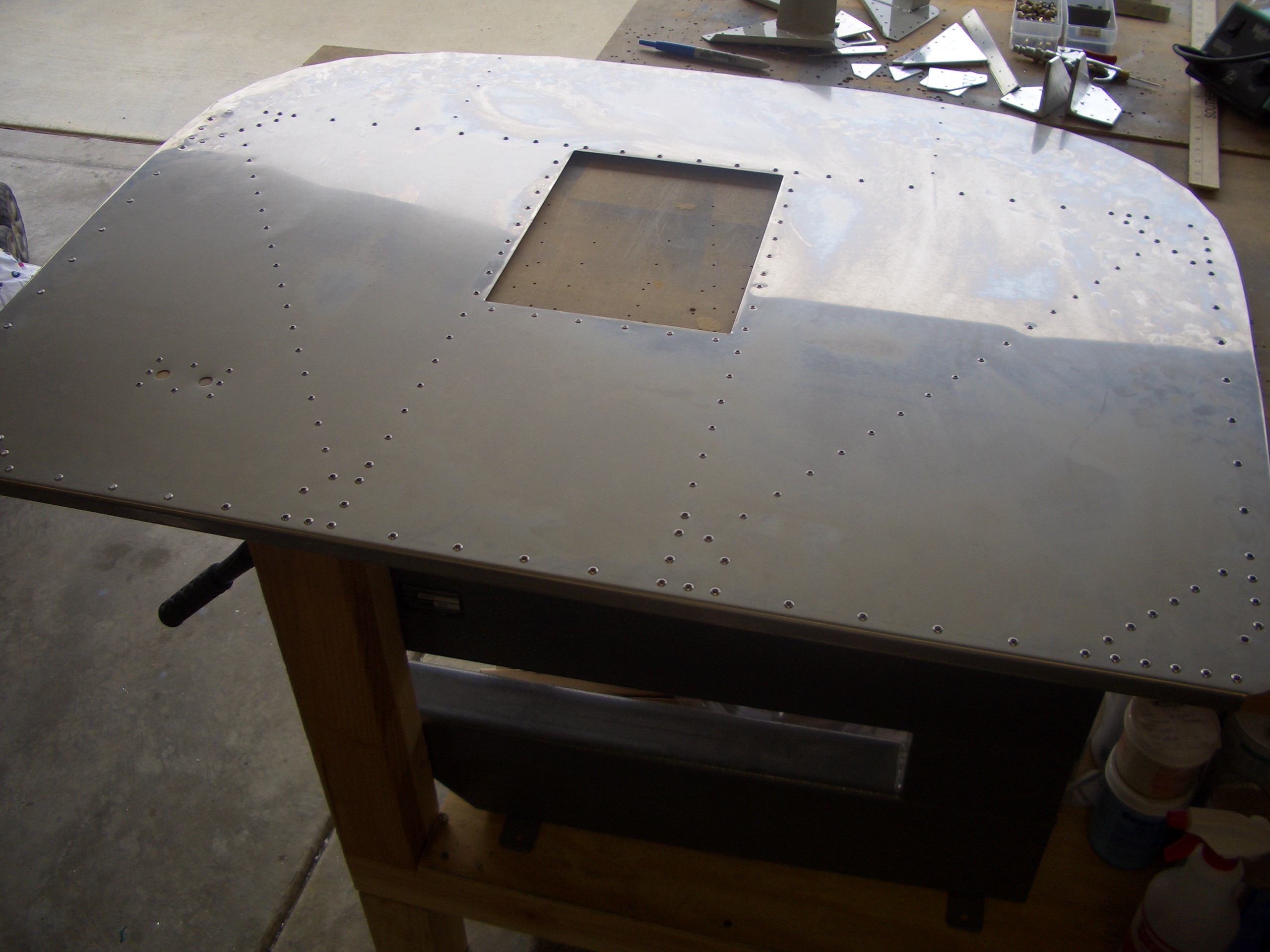
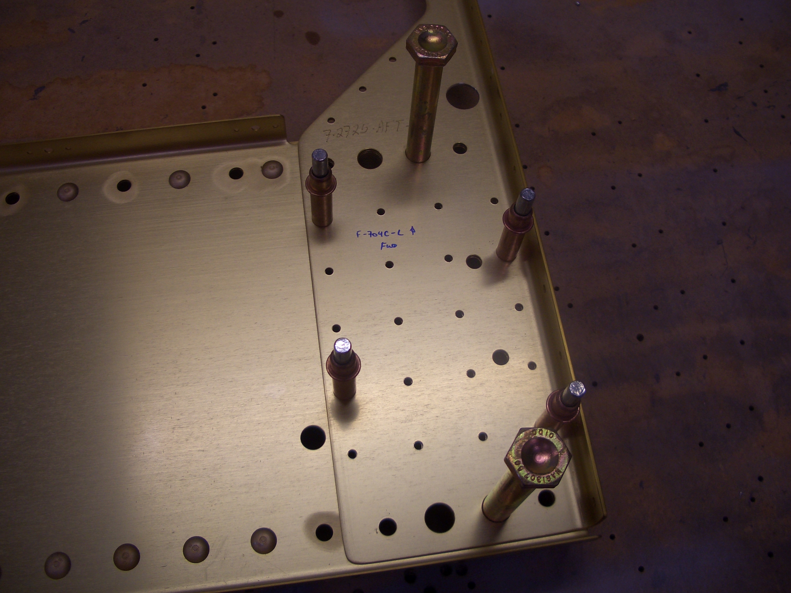
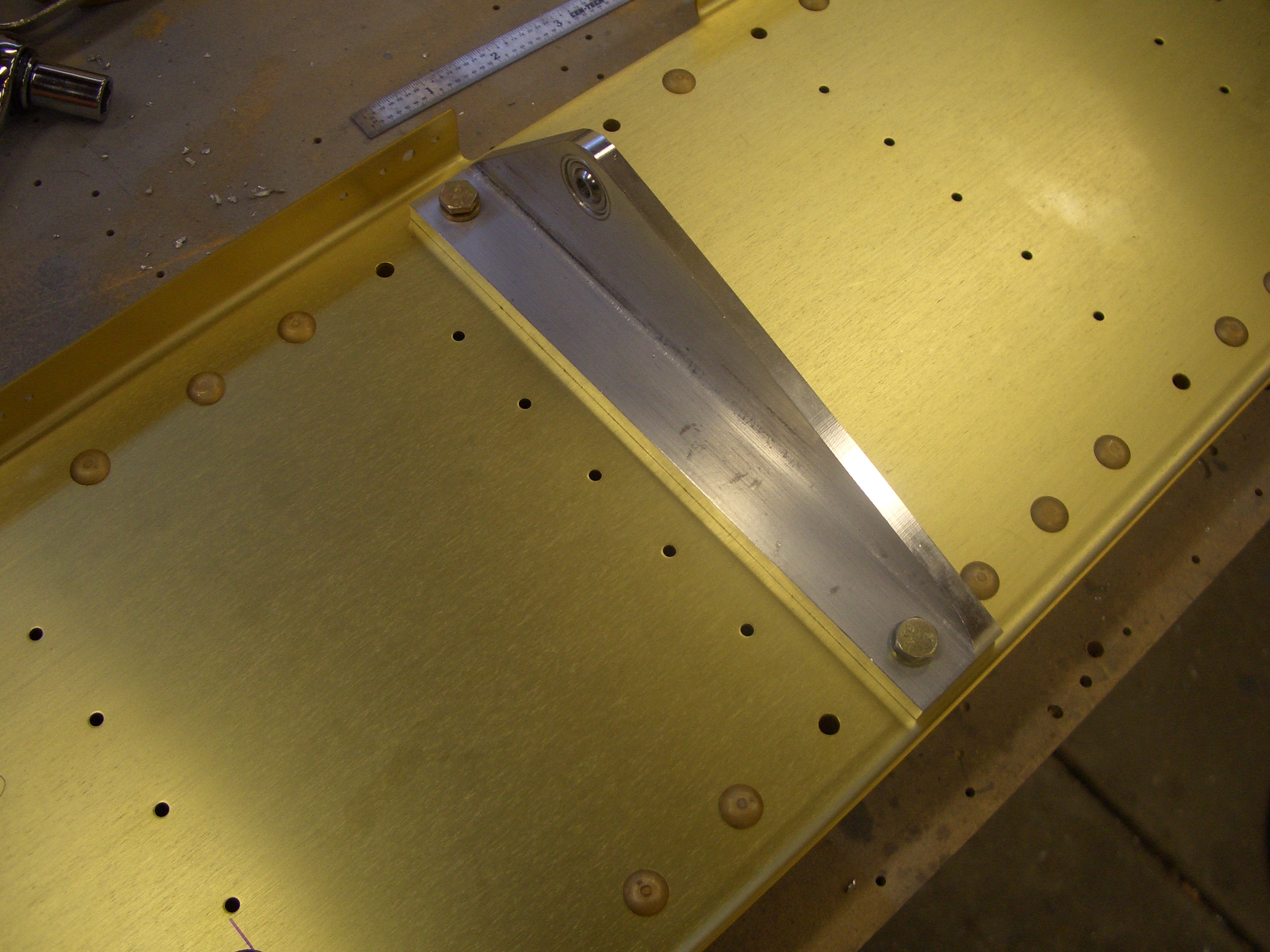
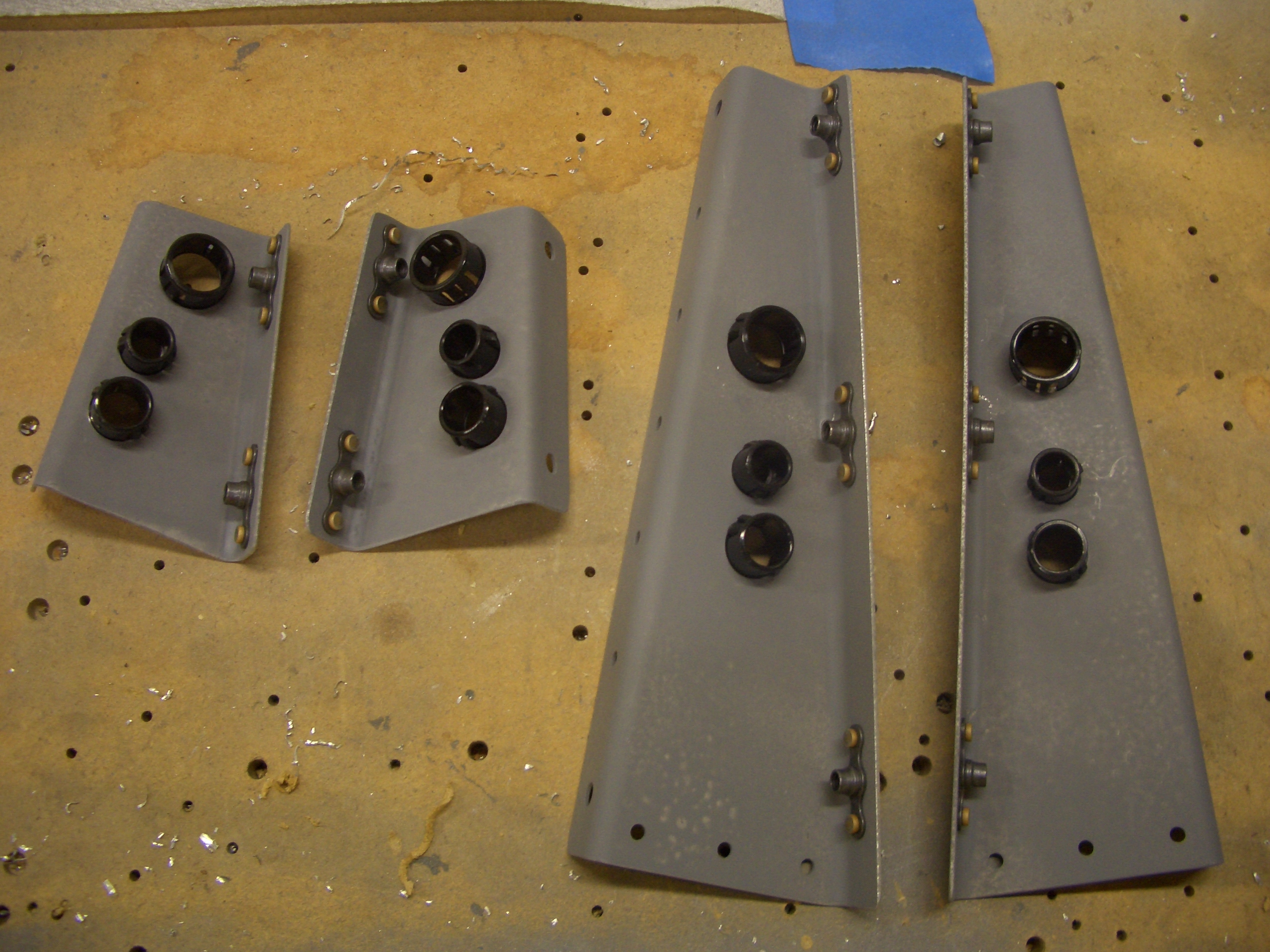
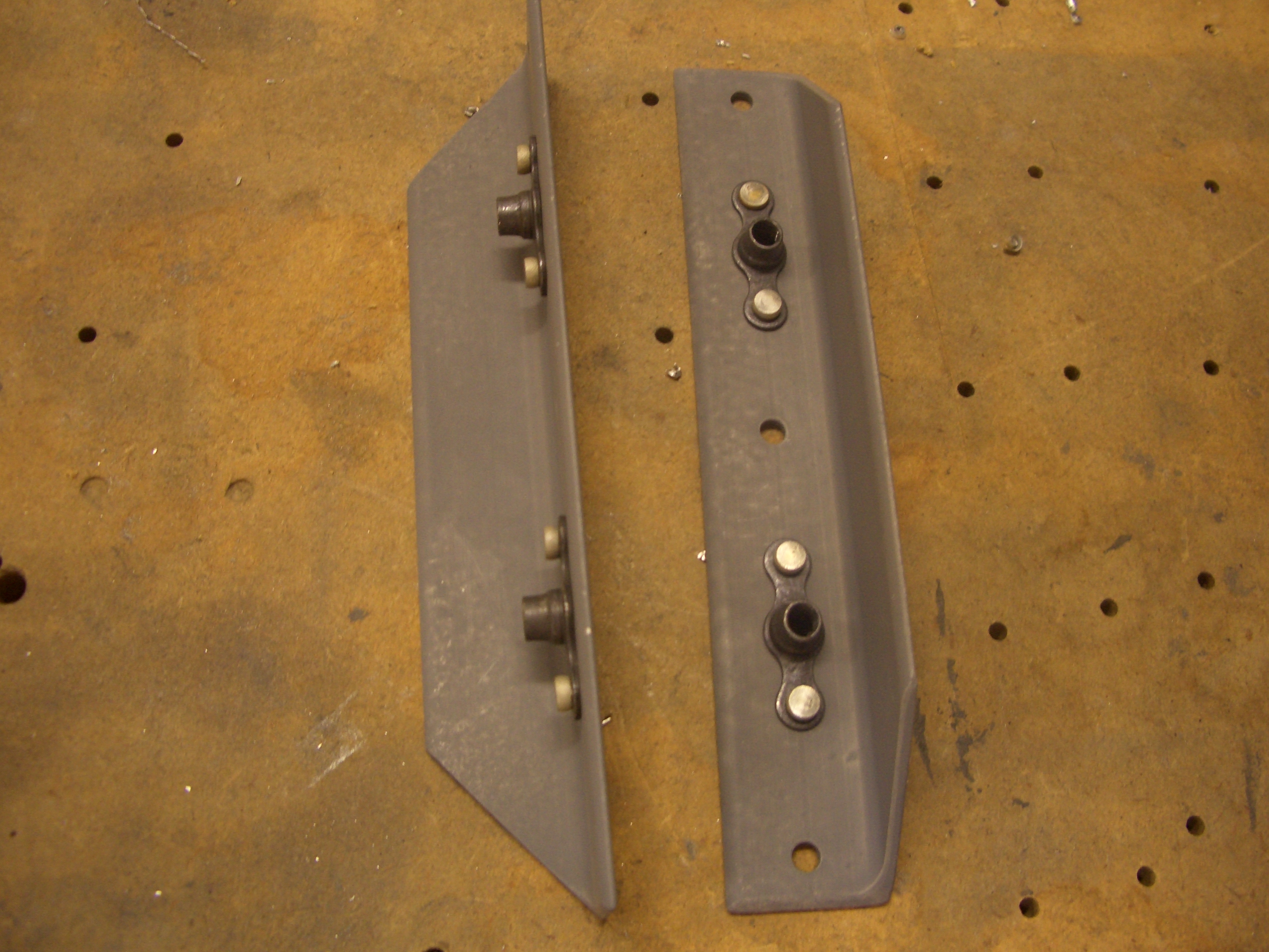
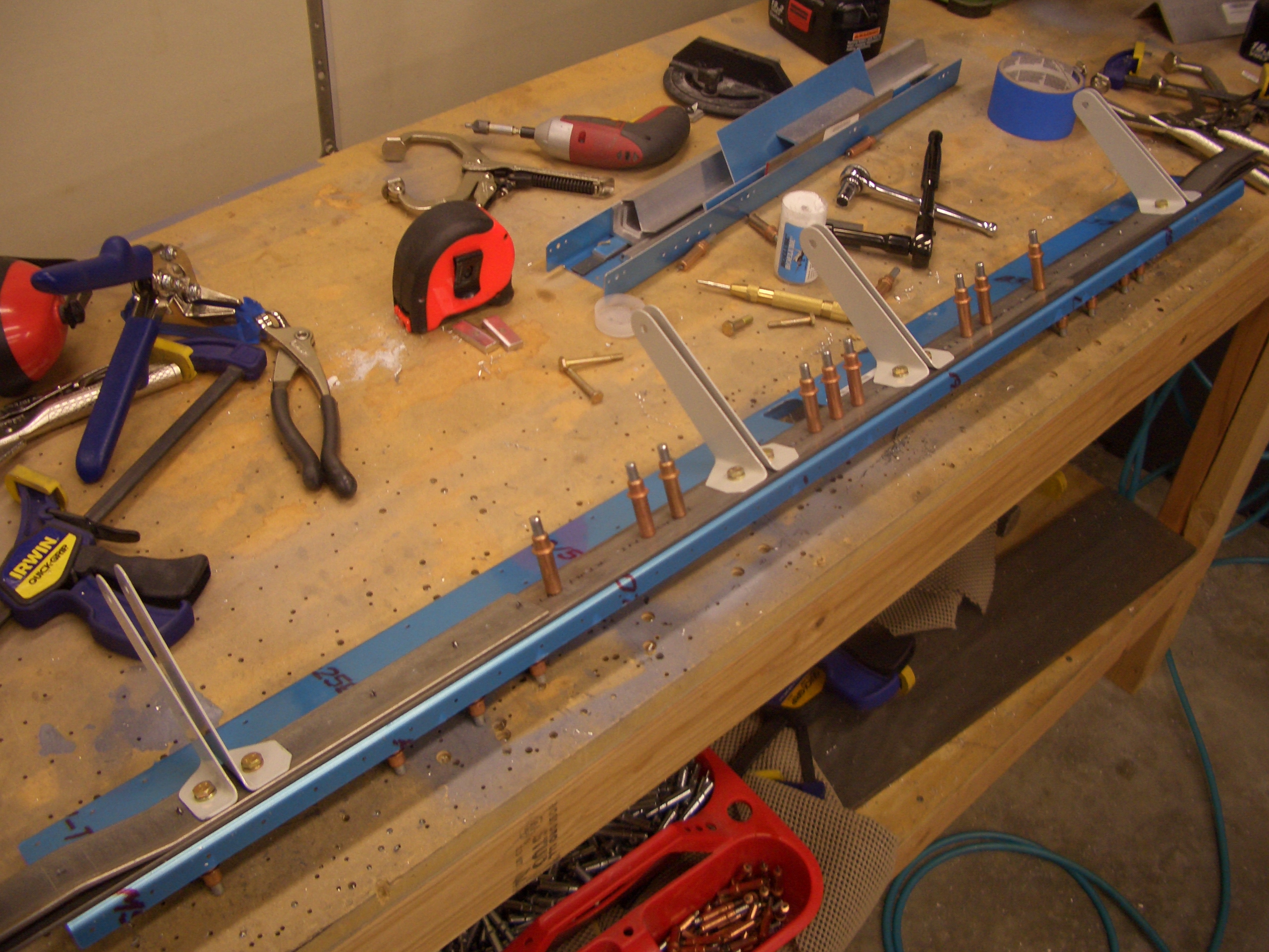
There are a few more 5/8″ holes that need to be drilled in the forward and after center section spar webs for snap bushings that will allow for wiring runs to penetrate the center section.  Here are the two in the forward center section.  The plans call for SB625-7, but I ordered extra SB625-8 snap bushing to give myself a little more room for wire runs.

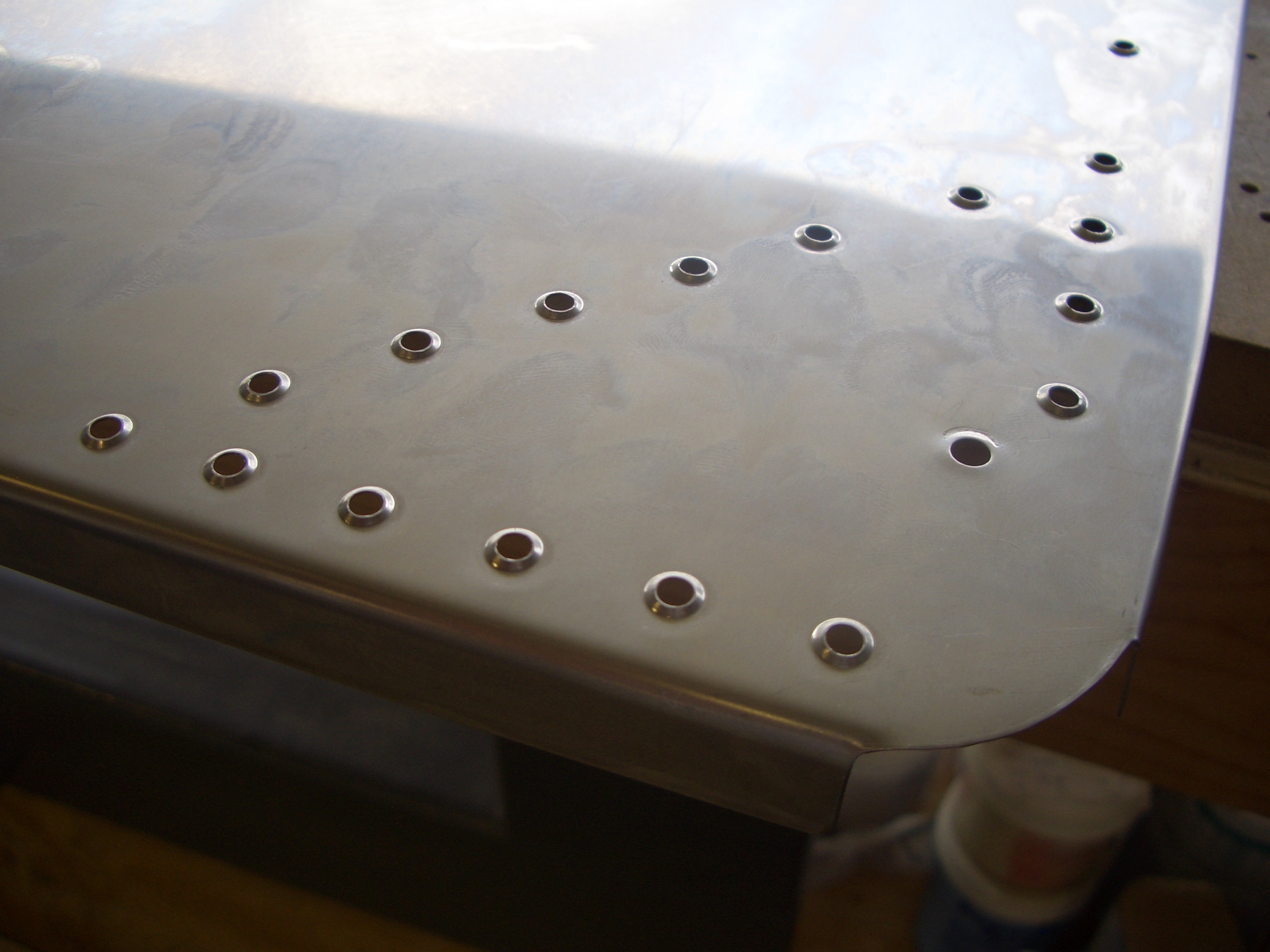
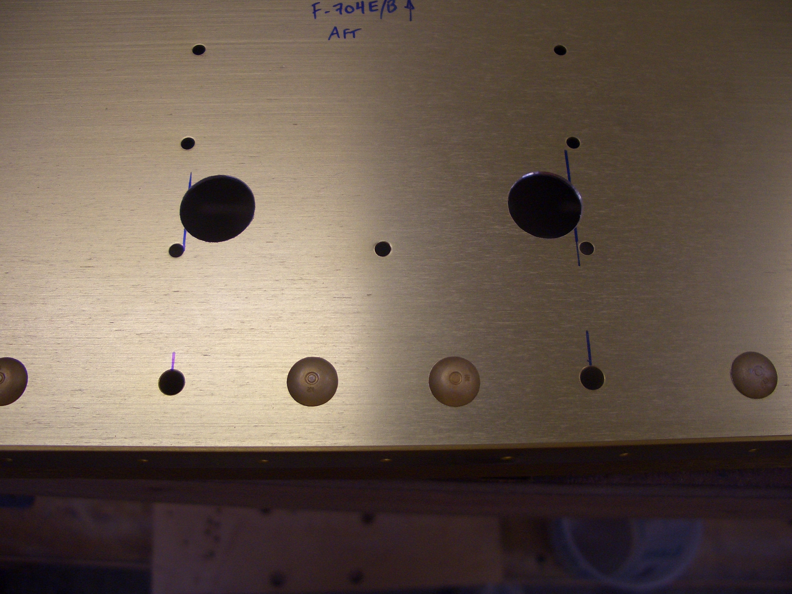
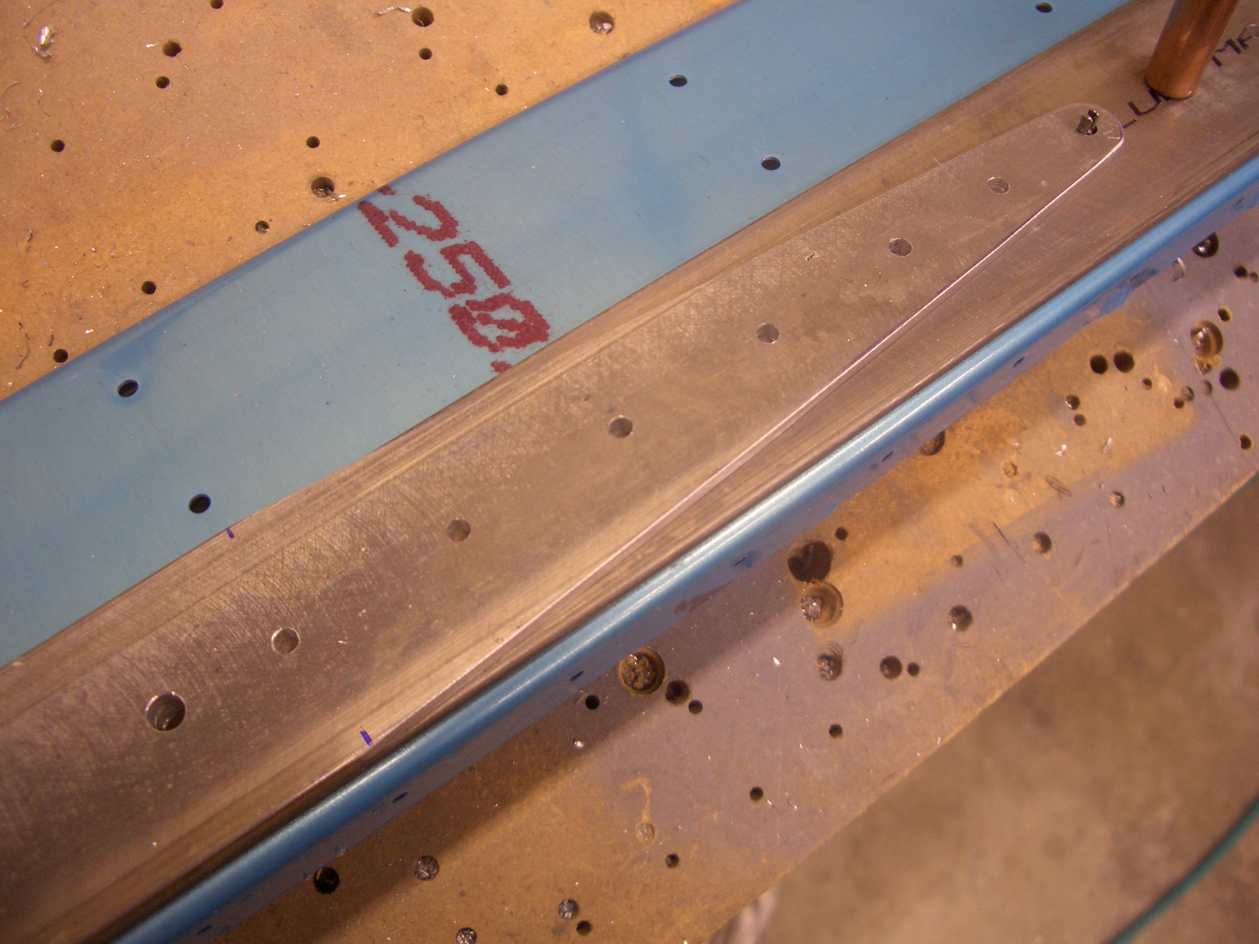
Here are the corresponding holes in the aft center section.  The seat ribs rivet here which is why there are two vertical rows of rivets.  Like most builders, I wonder why they didn’t just move these over a half inch or so so that they wouldn’t interfere with the rib.  As it is, I’ll have to cut away part of the rib flange to make room for the snap bushing.  I also ended up with the minimum edge distance on one of these holes (3/16″).  Nothing to worry about, but it would have been a non-issue if they have simply moved their holes inboard a bit.

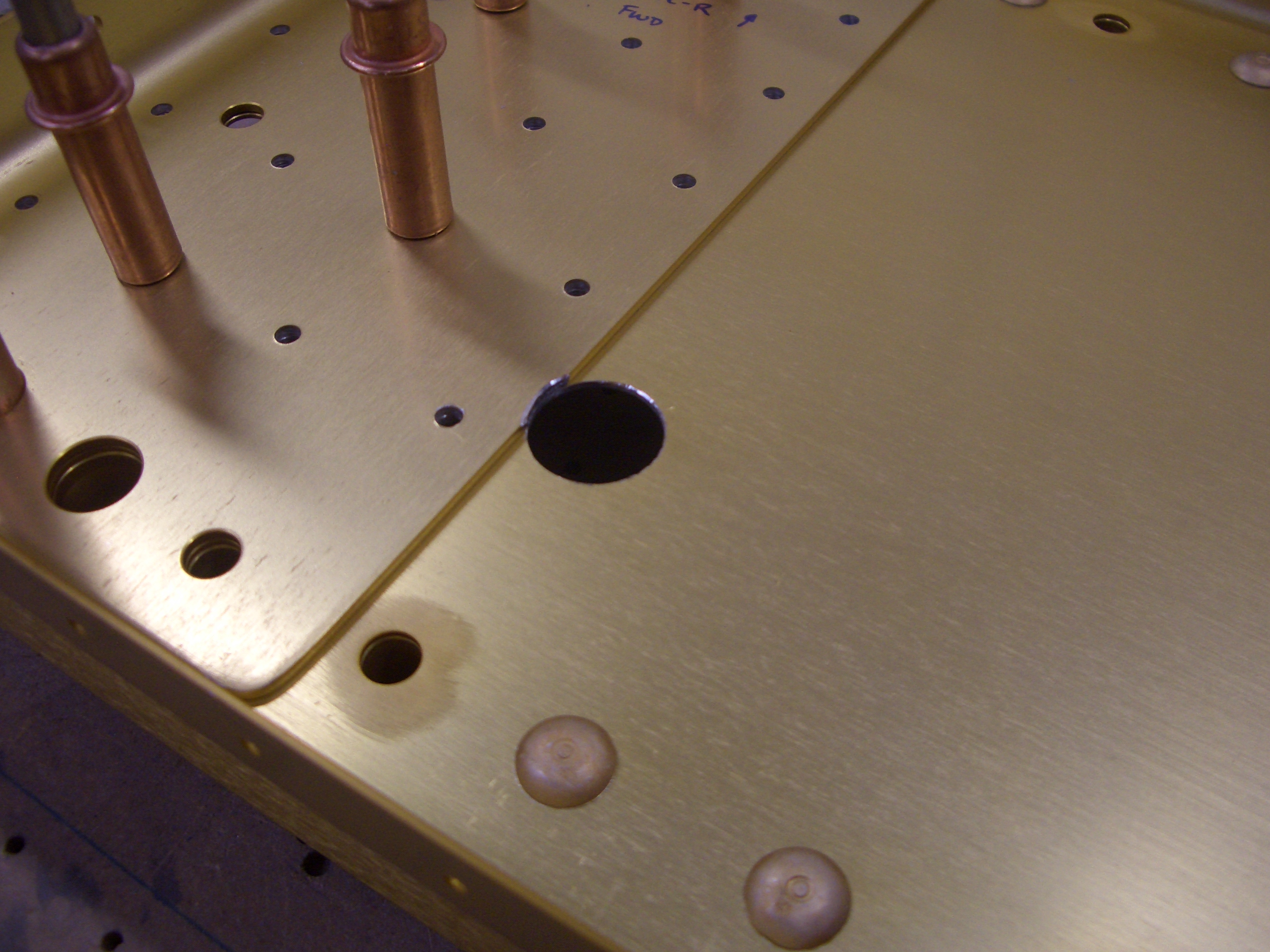
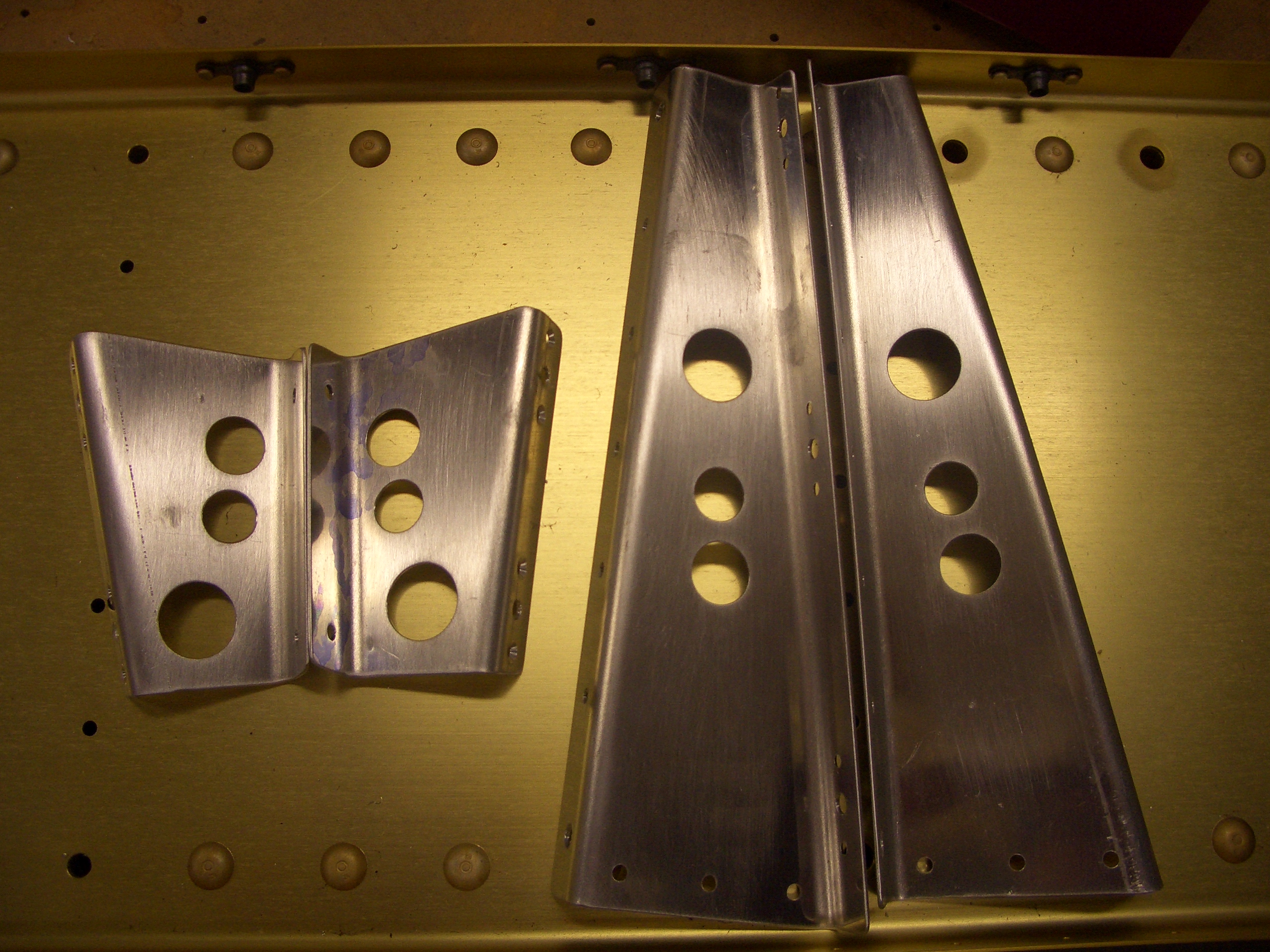
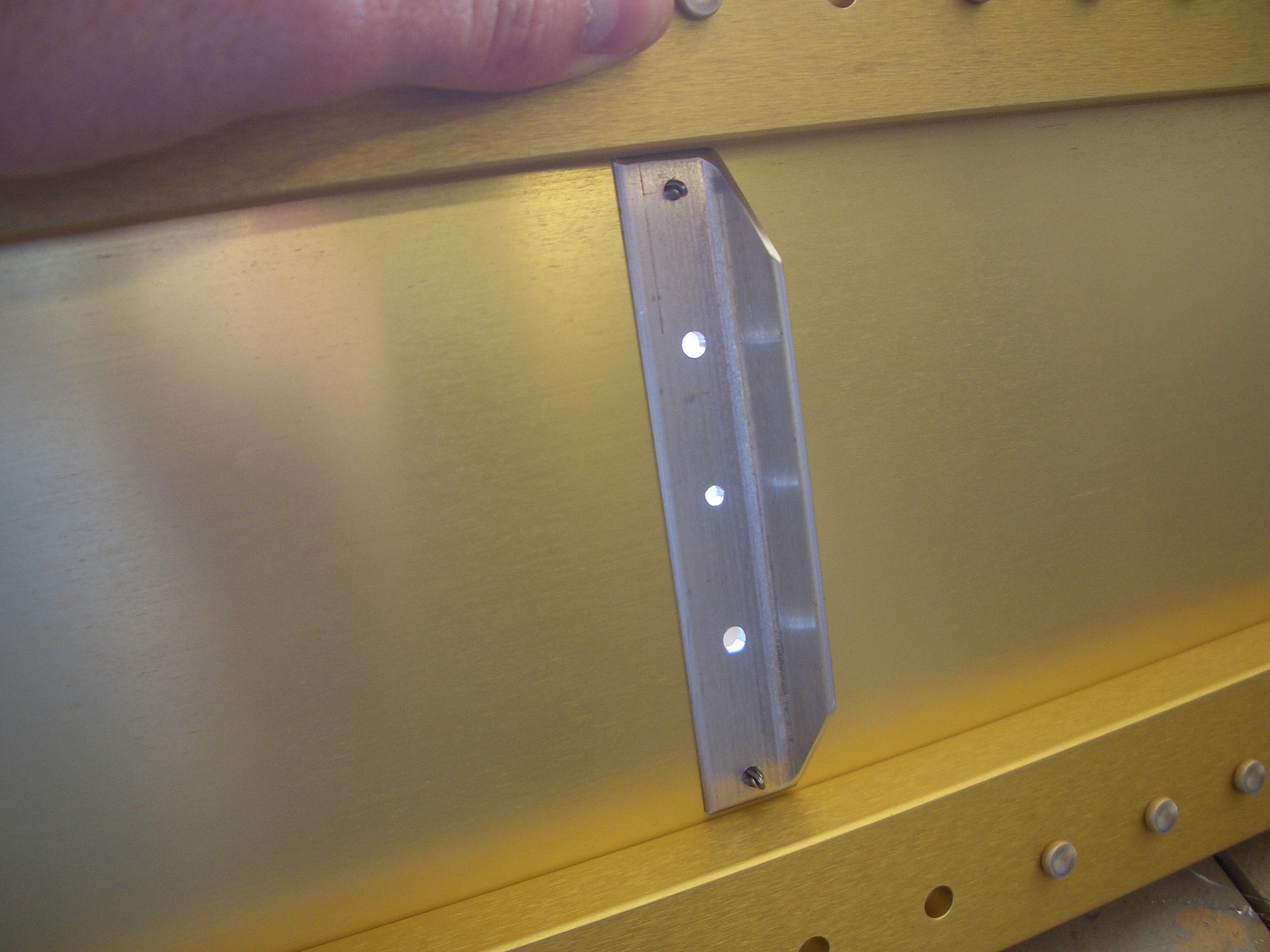
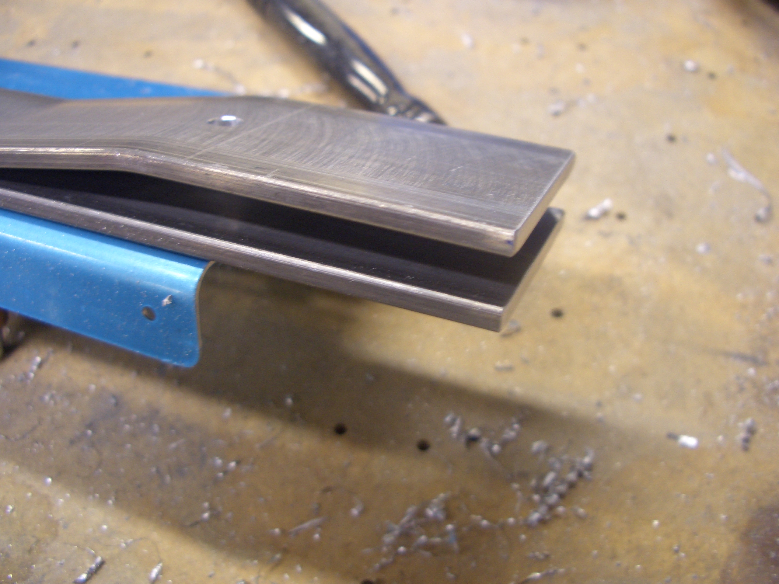
There are also outboard holes in both center sections for snap bushings.  If you zoom in on the picture, you can see that the hole slightly cuts into the side support.  Again it seems odd that they didn’t move these holes inboard a tiny amount to eliminate this interference.

Attached Control Sticks

I fabricated the control stick bushings and mounted the control sticks tonight.  I’m still not happy with these though.  The pilot’s side stick has a little bit of play between the stick and the bushing, and the passenger side is binding a little bit.  It’s late though, so I’ll work on these more tomorrow.

Drilled Control Mounts

I drilled the control mounts to the aft center section.  This basically entailed laying out and drilling the top hole then bolting the mount in place and squaring it to the spar.  After clamping it in firmly in place, the other hole can be back drilled through the spar.

Center Section

I started out tonight by finishing the work on the controls.  After a little fiddling with both sides, I got everything working nicely with virtually no play.  I disassembled everything so that I can get the control mounts prepped and primed.

The plans say you can optionally remove the outlined material from the control mounts to save weight.  I’m trying to save weight where I can, so I’m doing most if not all of these optional steps.  I started by drilling some #30 holes to define the radius of the interior angles.

I cut out the bulk of the material using the band saw.  After this picture was taken, I smoothed out the cuts with a vixen file and the scotchbrite wheel so that these are ready for priming.

The center section has 18 K1000-08 nutplates that need to be installed on the top flanges.

I also deburred the edges of the center cover supports and match drilled these to the spar.  Nutplates are installed on the front flange and holes are drilled through the webs for snap bushings, but these can wait until tomorrow.


Purchased Teflon/Tefzel Wire Stripper Blade

My Ideal StripMaster wire strippers came with the L-4421 knife blade.  This is fine for typical PVC insulation that most things are wired with, but it isn’t ideal for the tefzel insulated wire used in aircraft; the sharp edge can nick the wire.

The correct blades for teflon/tefzel are L-5211, but these are expensive (~$100).  I lucked out and found a set on eBay for $10 though so I picked them up.

Finished Cover Support Ribs

I fabricated the web stiffeners that go on the other side of the shorter cover support ribs.  The plans don’t include the 45º cuts on the opposing flange, but I misdrilled the end holes, so I cut the flanges to remove the holes.

I primed the cover support ribs and installed the nutplates and snap bushings.

I also primed and installed the snap bushings on the web stiffeners.

Here is everything installed.  The web stiffeners are riveted on the other side of the spar web under the two short cover ribs.  The short cover support ribs are screwed to the nutplates installed on the web stiffeners.  The longer cover support ribs are bolted through the spar bars at the top and bottom of the rib and riveted to the spar web through the middle.  If you look closely, you can see that the lower rivet in these ribs is missing.  I’m going to have to use my double offset rivet set to reach these and I’d rather wait until I have a riveting partner to use that.

Rear Spar Bulkhead

My buddy Andre stopped by today to give me a hand with the rear spar carry-through bulkhead.  First up is to shoot the two rivets I couldn’t do easily yesterday.  I didn’t get a picture of it yesterday, but I also riveted on the main spar uprights.  A few of these rivets could be squeezed, but most needed to be shot and bucked.  I’m definitely getting the hang of doing that solo.

The rear spar bulkhead starts with a could of beefy pieces of 2024-T4 bar stock.  The lower one in this picture runs all the way across the bulkhead and carries the major portion of the load.  Shorter pieces of bar stock with a couple of bends in them are riveted to these to create a socket which will receive the rear wing spar.

The lower seat belt attach points are drilled and bolted to the rear spar carry through structure.  The technique here is to mark and drill one side that then clamp the other side in place with a 3/16″ spacer.  An AN3 bolt is exactly 3/16″ thick, so clamping one of these between the anchors creates the perfect spacing.  The holes in the top of the anchors (off the top of the picture) are held in alignment with an AN4 bolt.  The other anchor can then be back drilled through the spar.  You can also see here the outboard seatbelt attach points require the anchors to be cut to clear adjacent rivets.  Here, the left anchor has been cut, but the right one is still full size.

Here are all four seat belt attach points match drilled to the spar.

The shorter spar bars are tapered for weight reduction.  You need to make sure that the last rivet has 1/4″ edge distance all around the radius.  By positioning this end first, I could easily ensure that.

Then the other end can be cut flush with the long spar bar.

While I was working on the rear spar, Andre fabricated the upper angles that will receive the canopy latch pins.

The angles fit behind the upper portion of this bulkhead.  I drilled the four corner holes so that I could use rivets to keep the three prepunched pieces in alignment.  The angle could then be clamped in position and the holes match drilled.  I’ve said it before, but these self-adjusting clamps absolutely rock.