Finished Jacks

I finished up the jacks this morning down at the Tech Shop.  I’m still not great with the MIG welder, but the welds on this are more than strong enough.  The base of the jack is welded to the frame and a bolt is inserted through the top ring to prevent the jack from moving.  After cleaning it thoroughly, I applied a coat of orange paint that approximately matches the jack.

Additional Filling Around Spinner Ring on Cowl

After pulling off the board I used to create a flat ring around the spinner, I sanded it flat with a long sanding block and added a little more filler to fill in the small depressions left by some wrinkles in the saran wrap.  I also tightened up the gaps between the upper and lower cowl halves a bit.  I’m such a perfectionist, that this part of the construction is going quite a bit slower than I’d hoped.  All of this will be highly visible on the finished plane though, so it’s worth the extra time.

Started Fabricating Jack Stands

I stopped by a metal scrap yard over lunch and picked up some scrap steel to make some jack stands.  I picked up some 4″ channel for the bases and 1″ x 1.5″ rectangular tubing for the angular supports as well as some 3″ ID tubing for the upper collar.  I cut and welded these up at the TechShop in about two hours after our local EAA meeting.  The angles aren’t welded to the bases yet since I ran out of time and I only had one jack with me.  I’ll wrap these up and paint them shortly.  The collar doesn’t fit tightly over the jack, so I’ll probably also drill and tap a hole in it so that I can insert a bolt to keep the jack from moving.

Wheel Pants, Plenum and Cowl Work

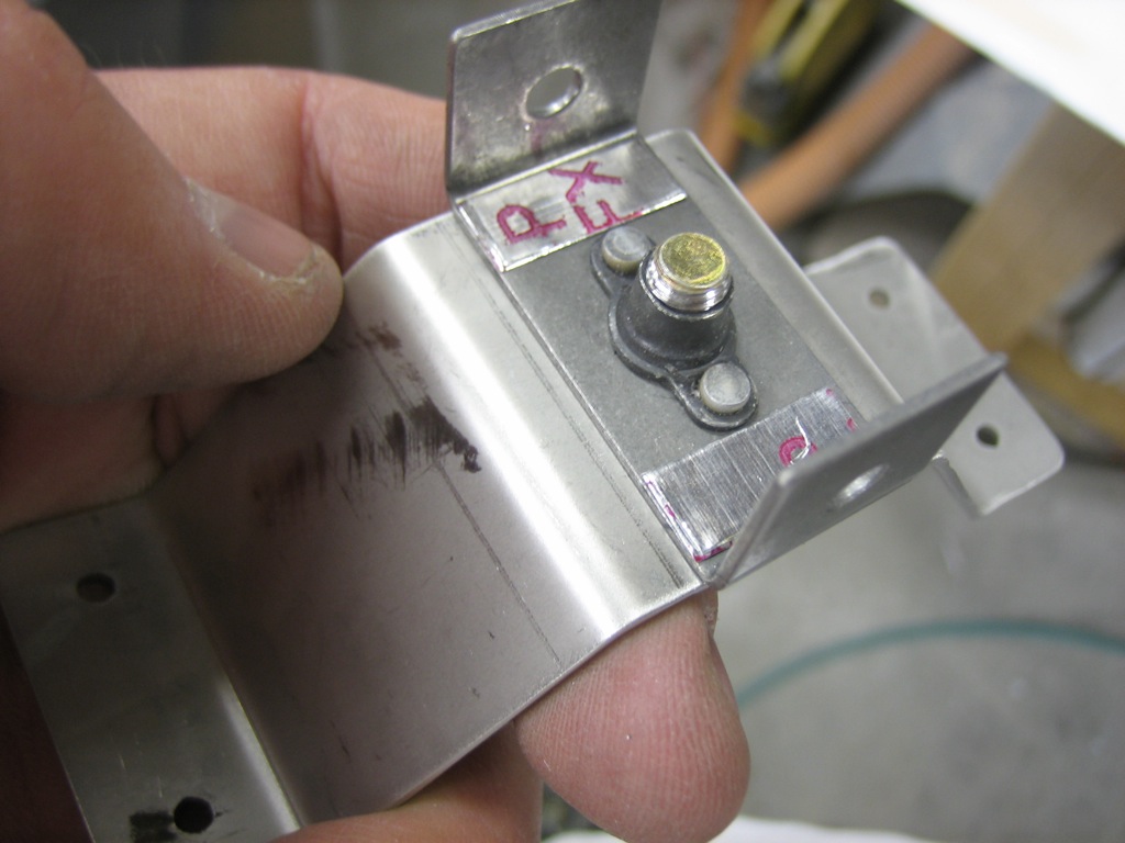
I trimmed the right wheel pant bracket to match the left and fabricated three more spacers.

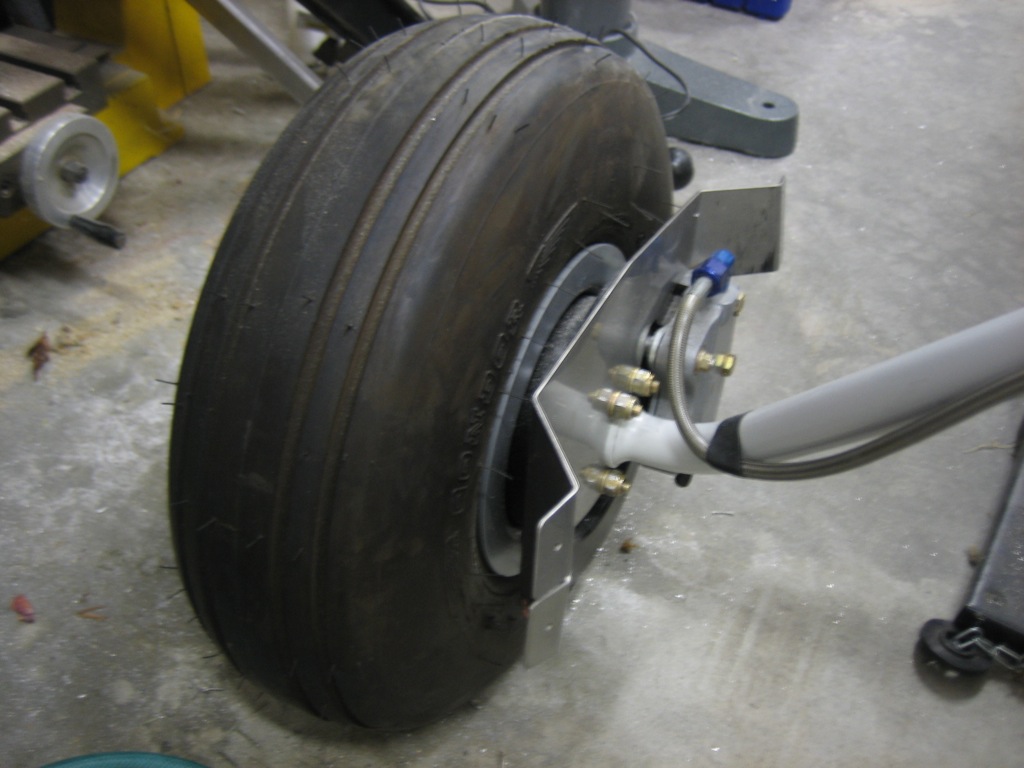
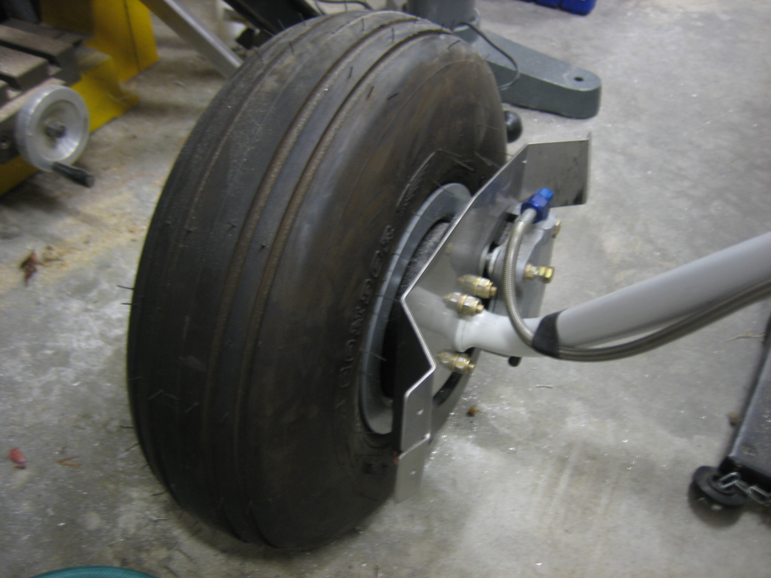
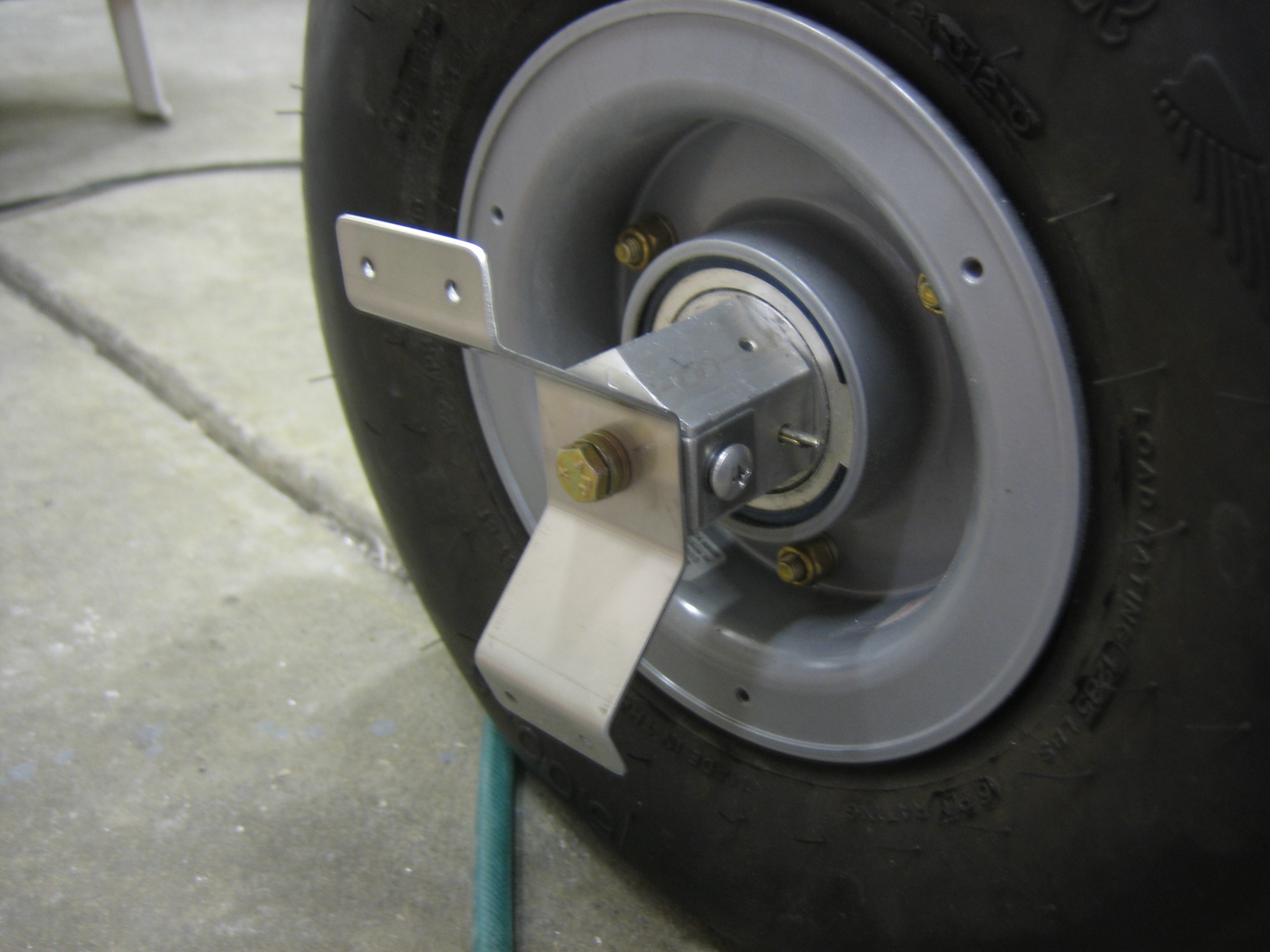
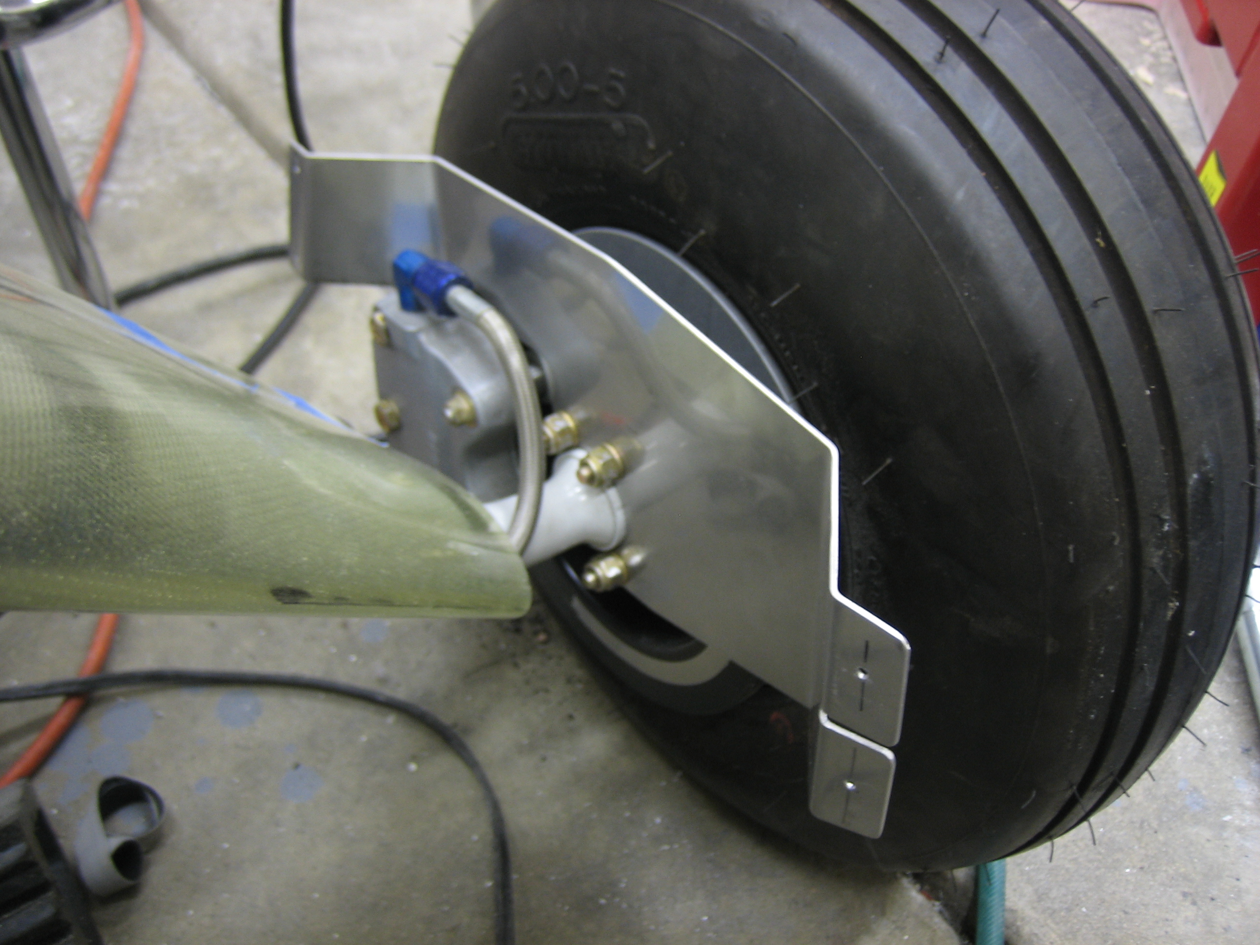
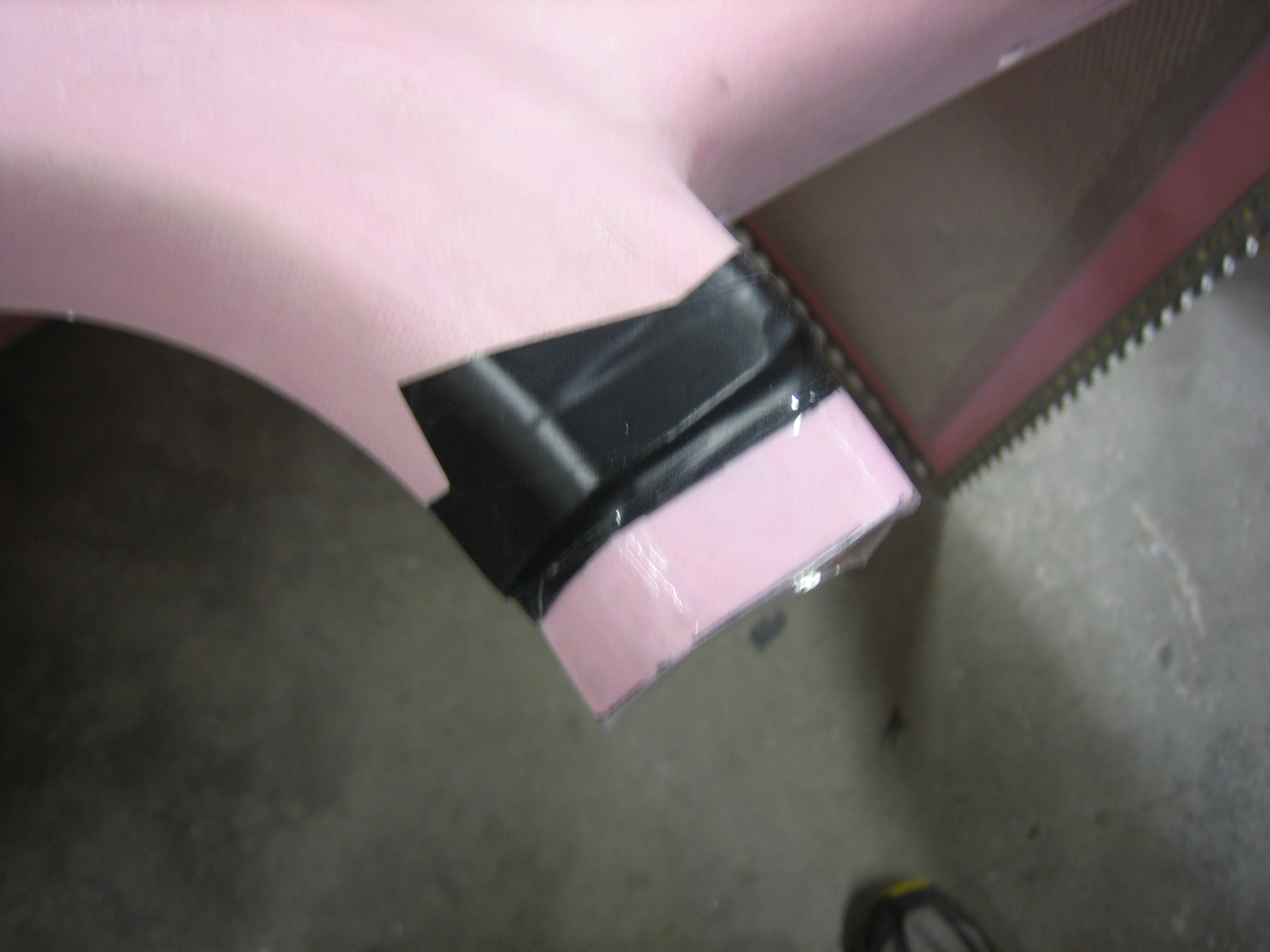
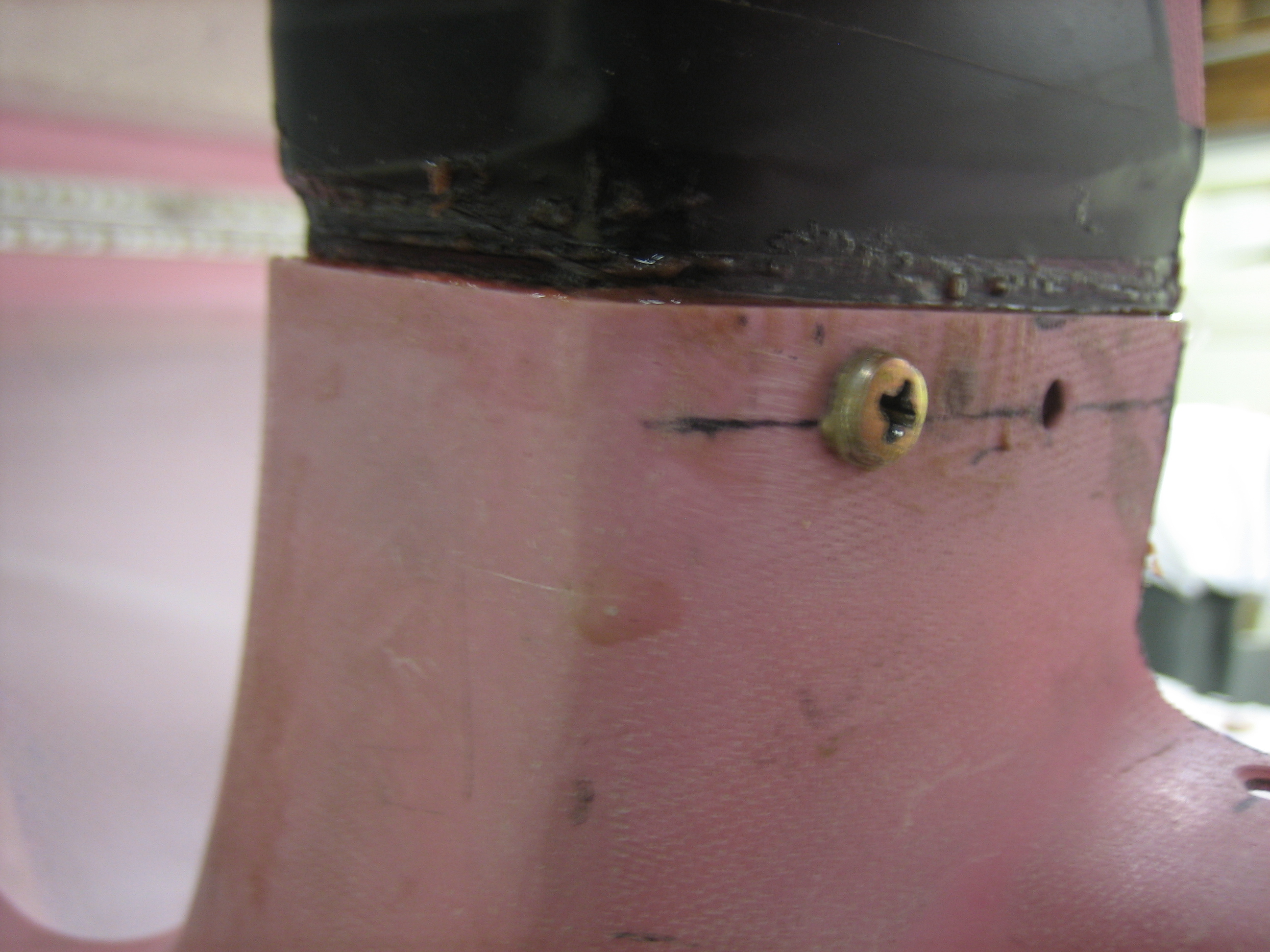
I then fit the outboard wheel pant brackets, but the attach point on the axle nut was rocking slightly which would have let the wheel pant move up and down a bit.  I used a few layers of aluminum tape to make the bracket fit much more tightly on the axle nut.

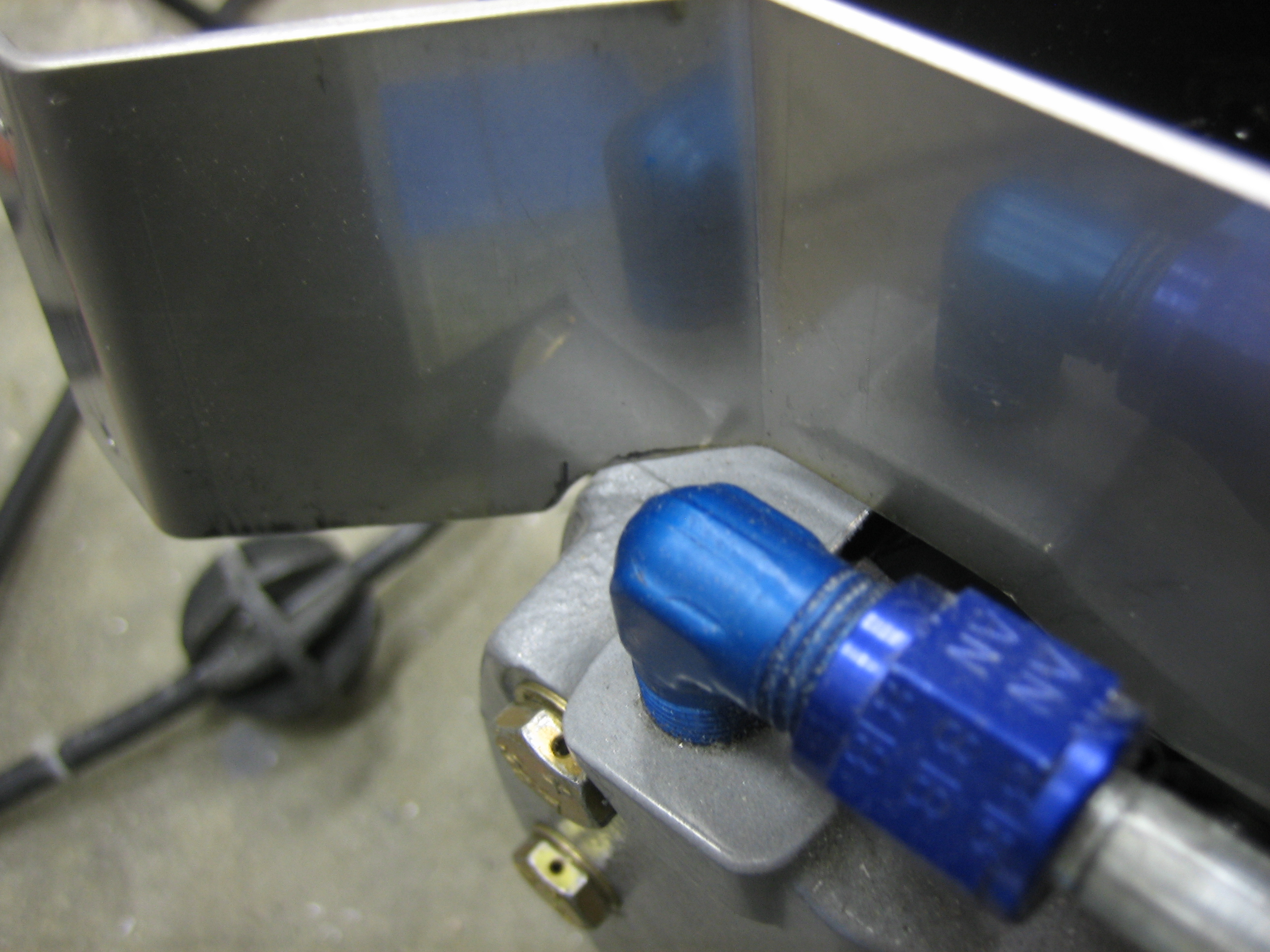
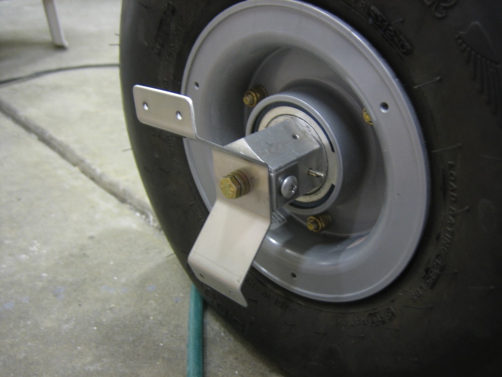
Here’s what it looks like installed.

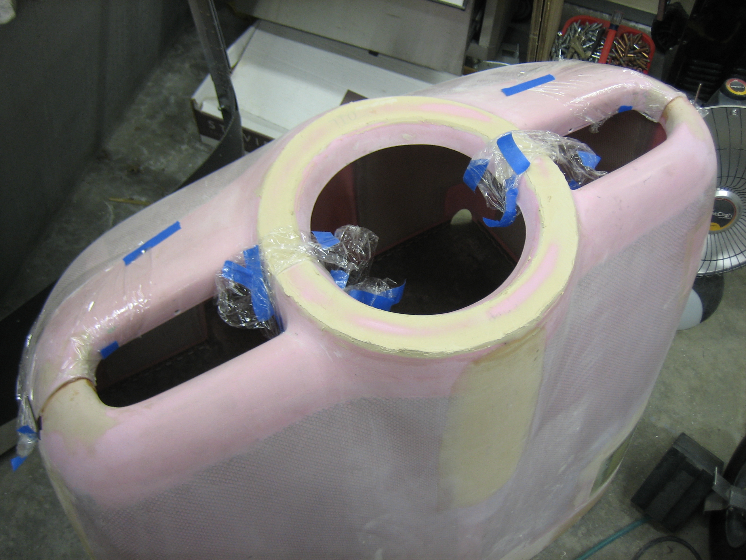
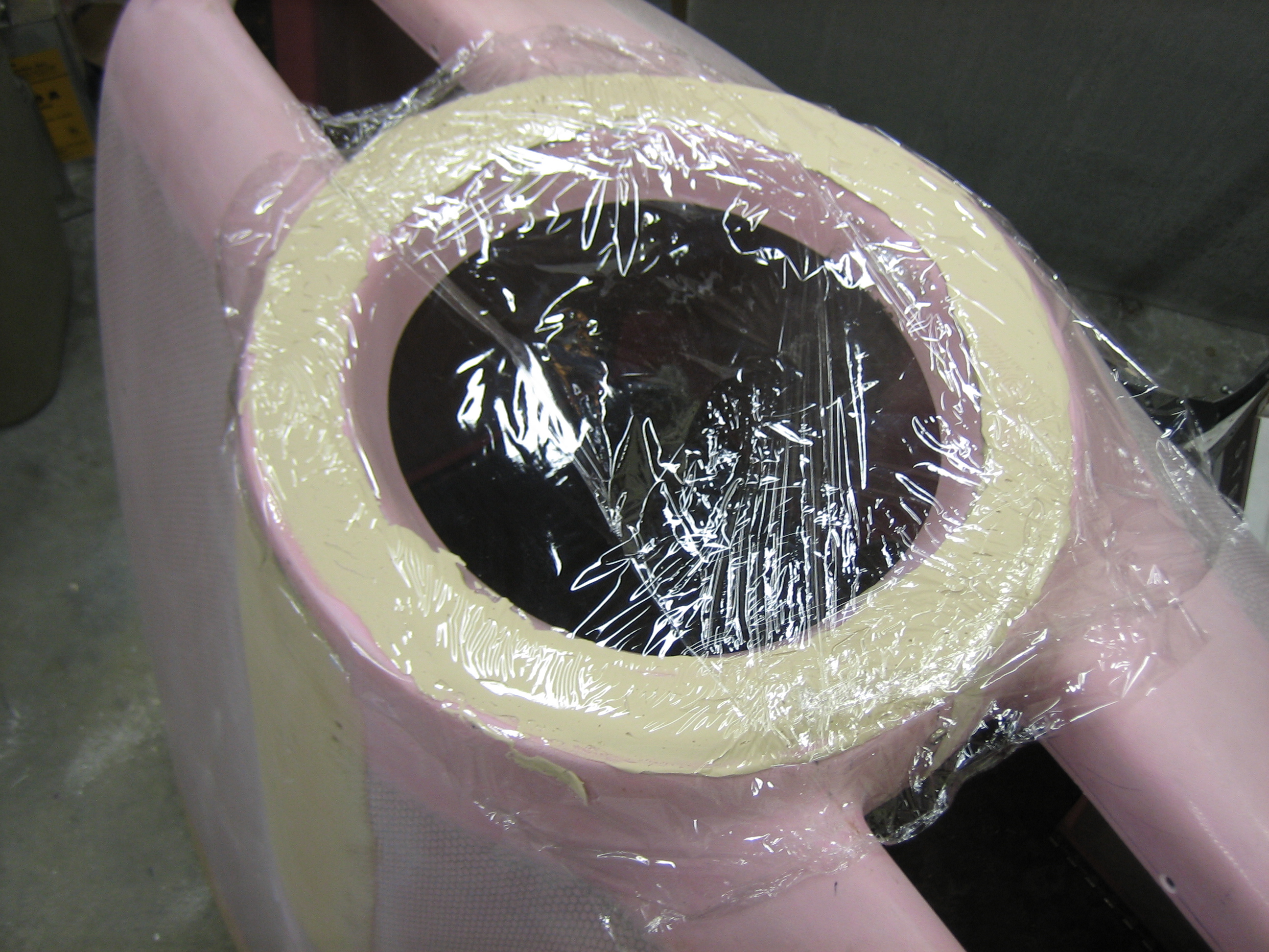
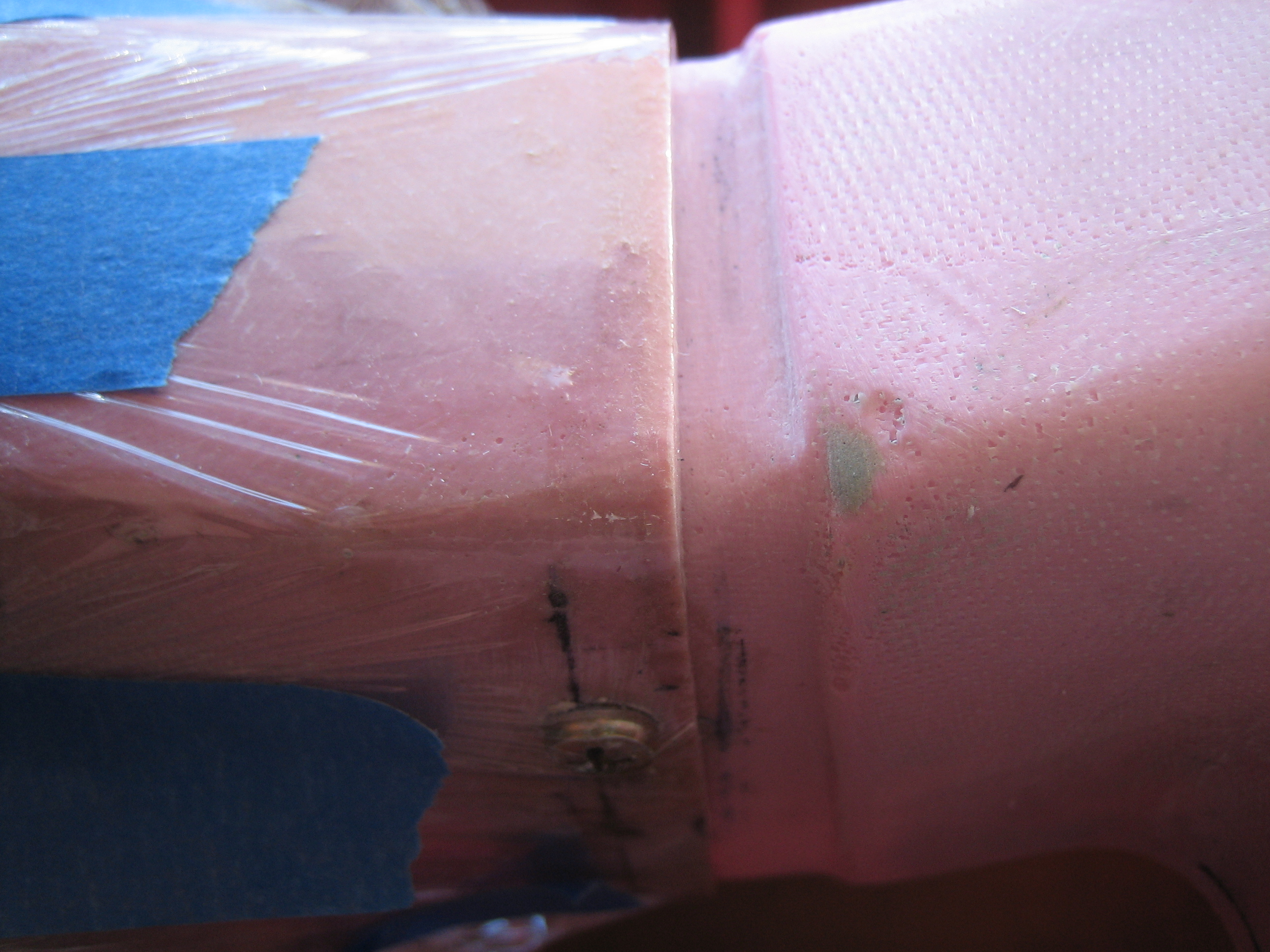
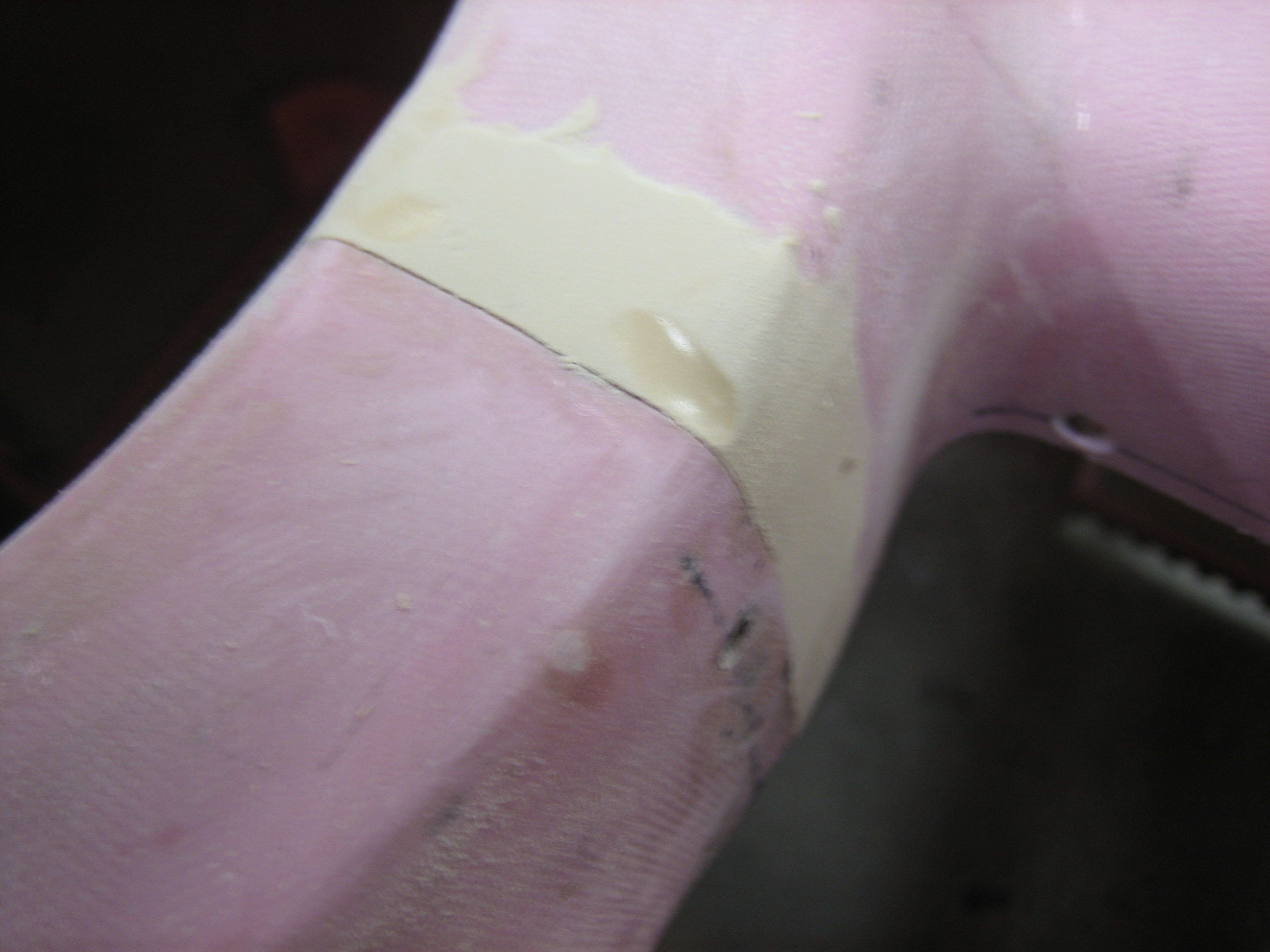
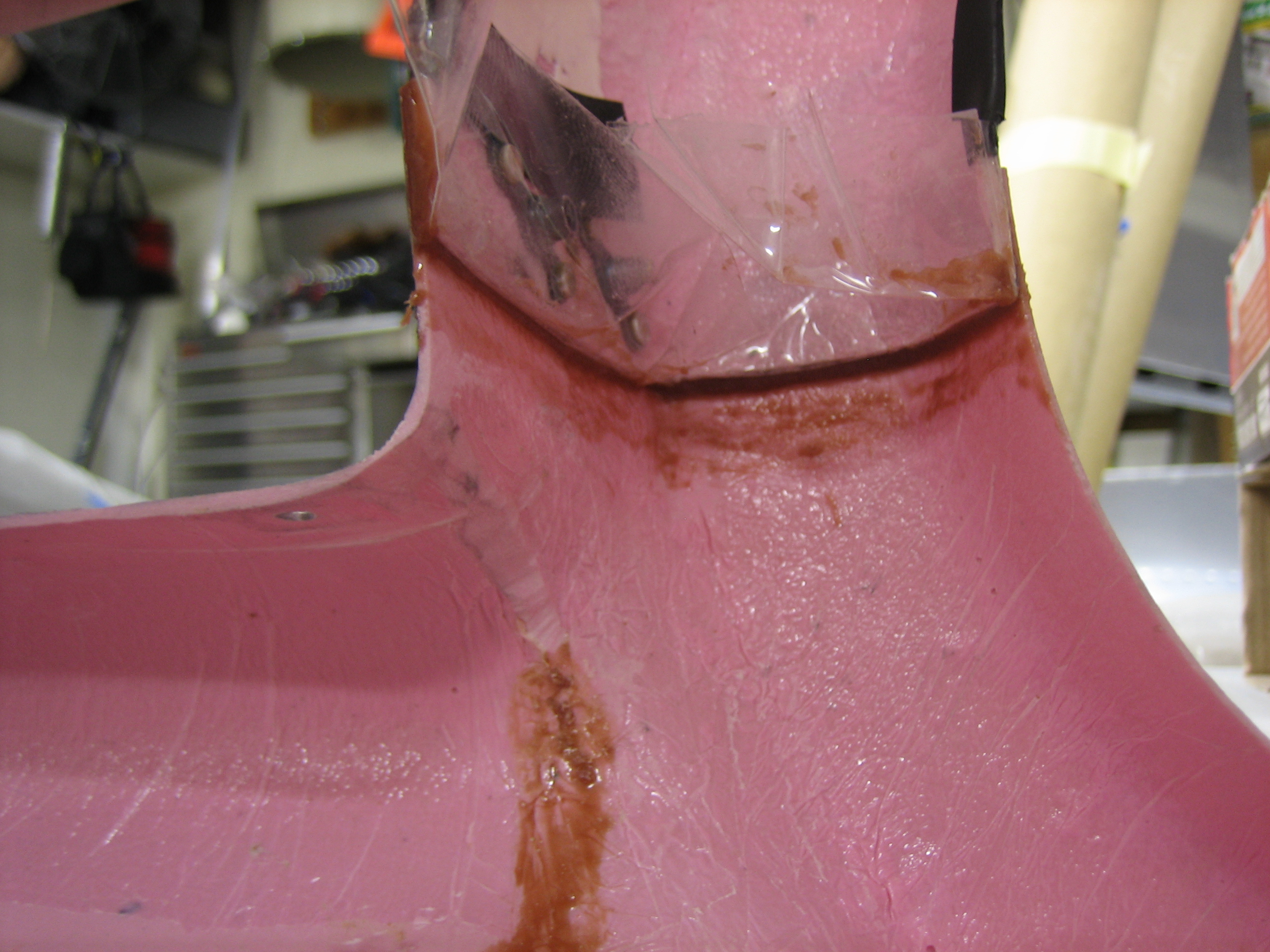
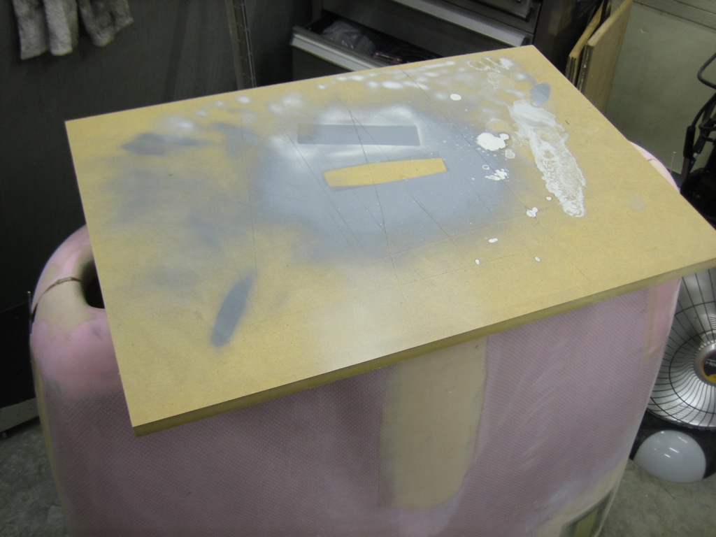
I’ve never been very happy with how uniform the spinner to cowl gap was.  The way the cowl was formed, the center of the ring where the upper and lower half join was slightly recessed and had a larger gap than the upper and lower portion of the ring.  To fix this, I mixed up some lightweight filler and spread it around the ring.  I then covered it with saran wrap.

I put a flat board over that and pressed down firmly until enough of the filler squeezed out that I could see the pink part of the cowl around most of the ring.

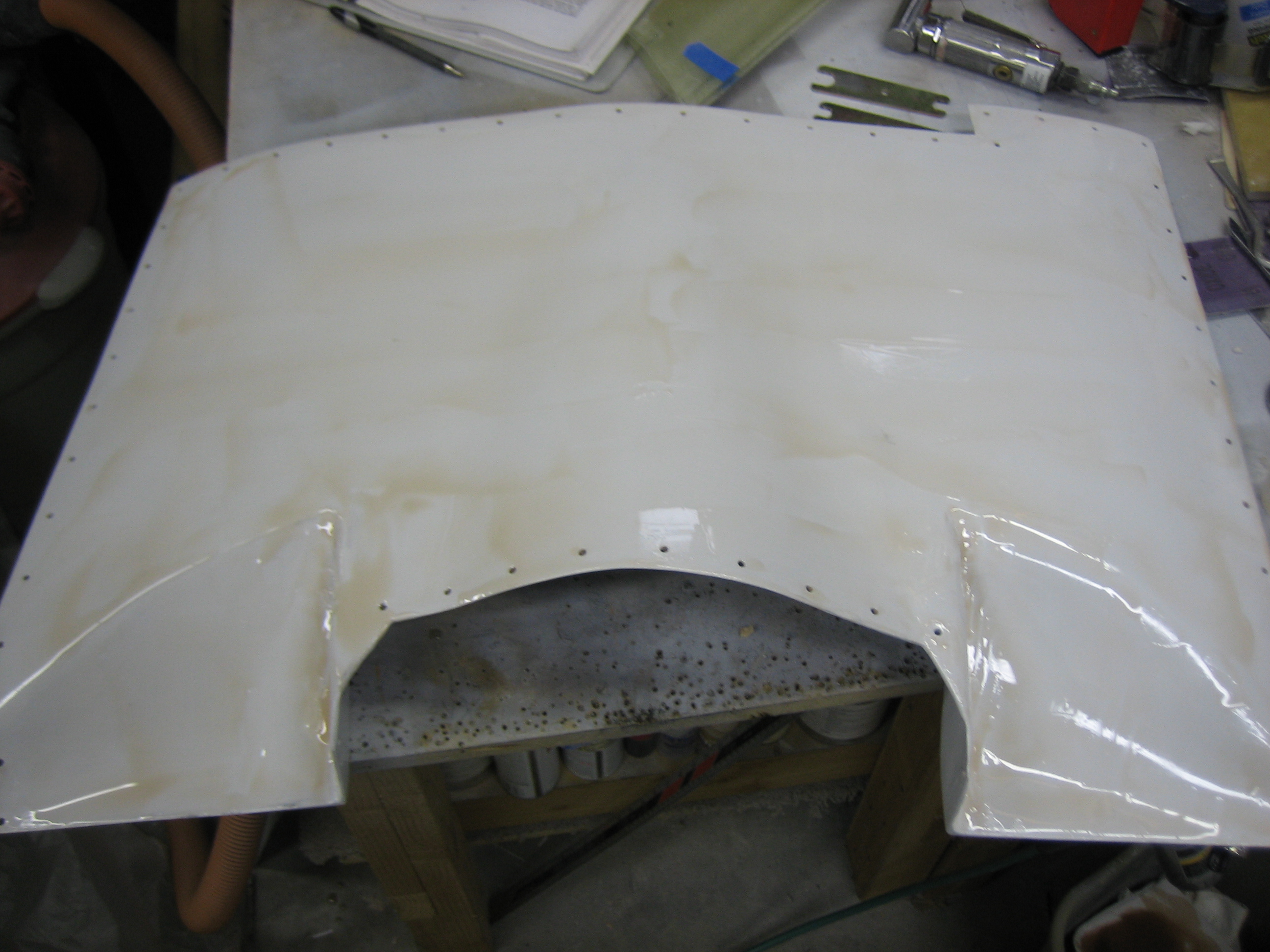
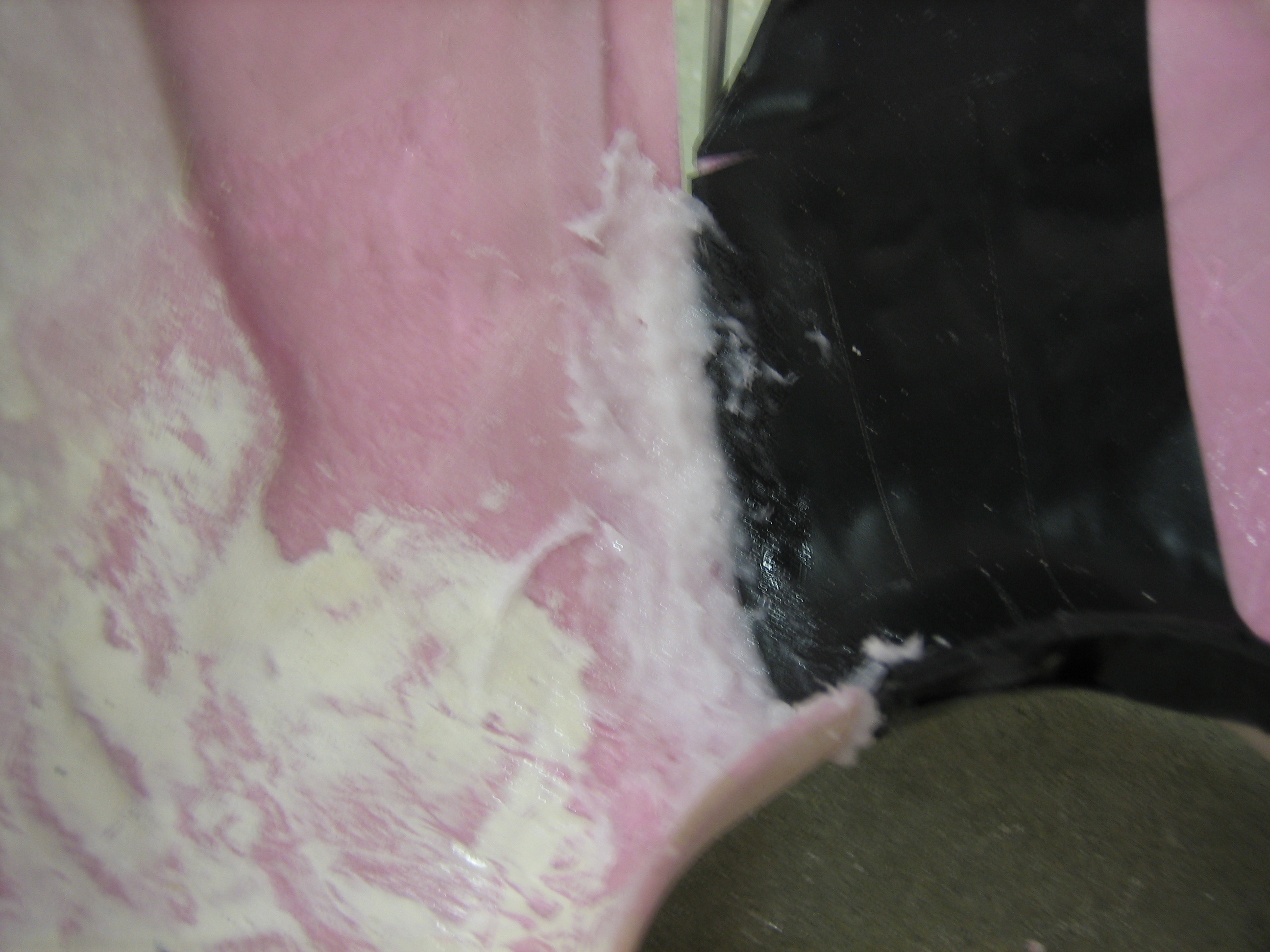
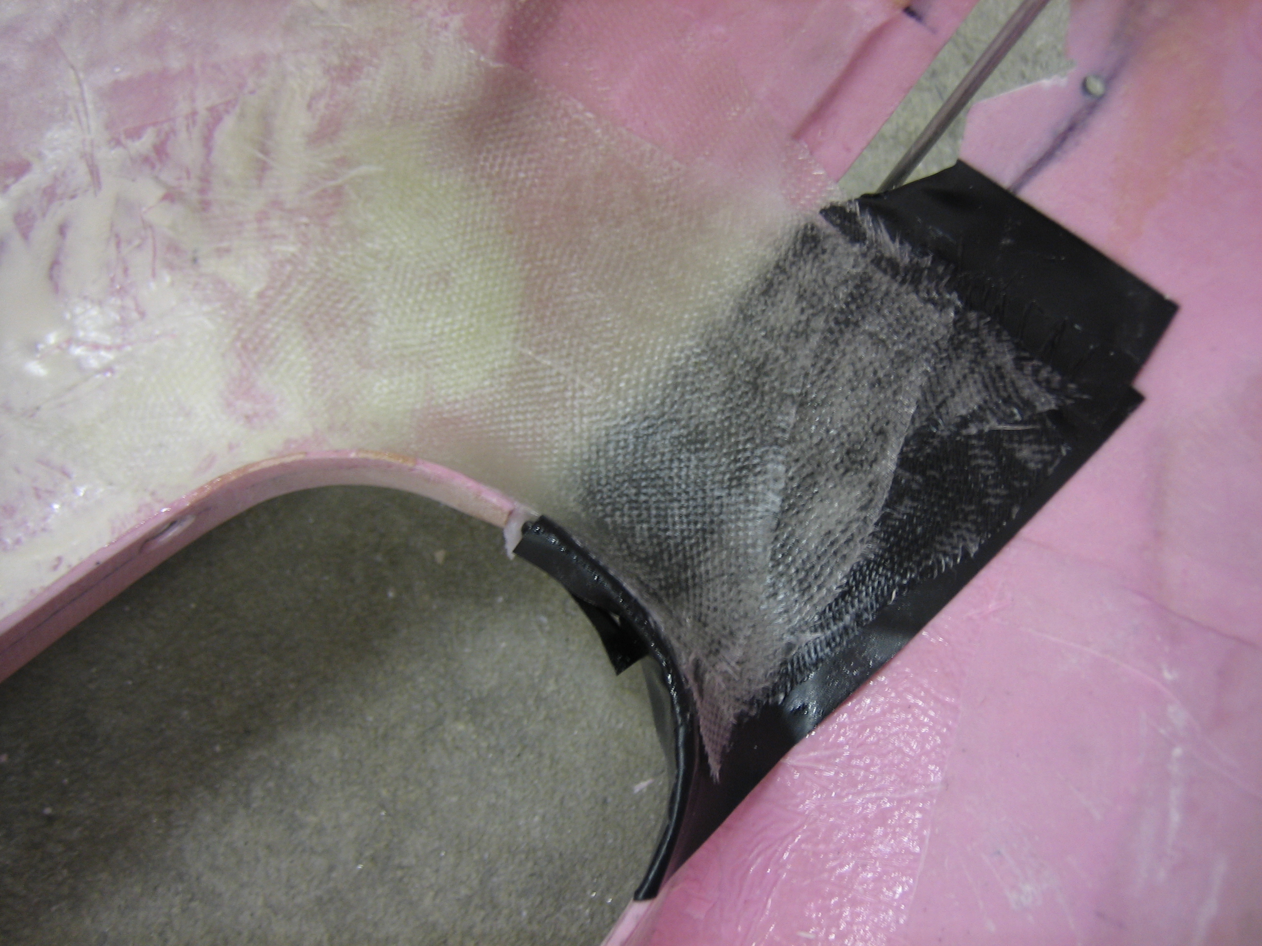
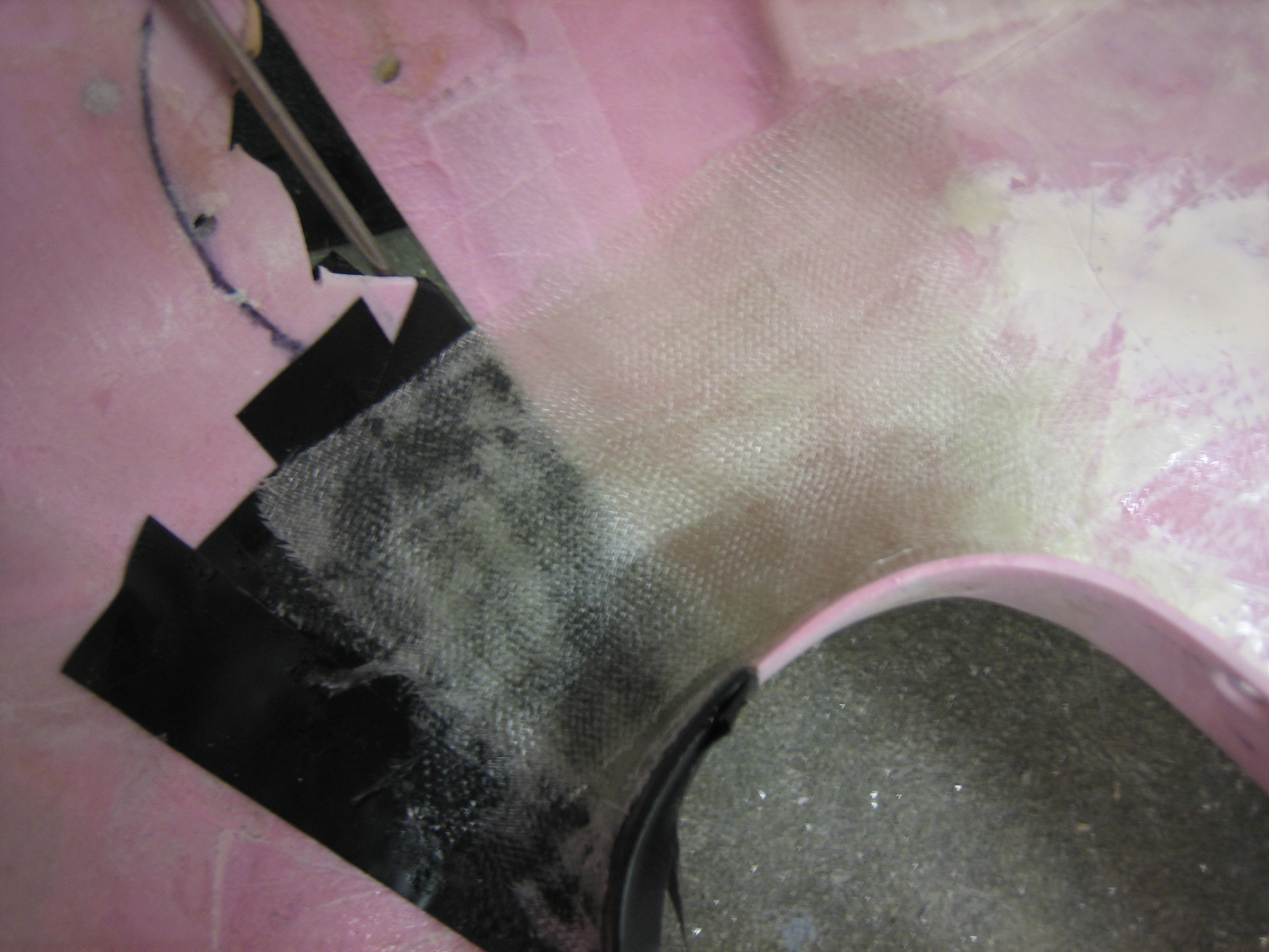
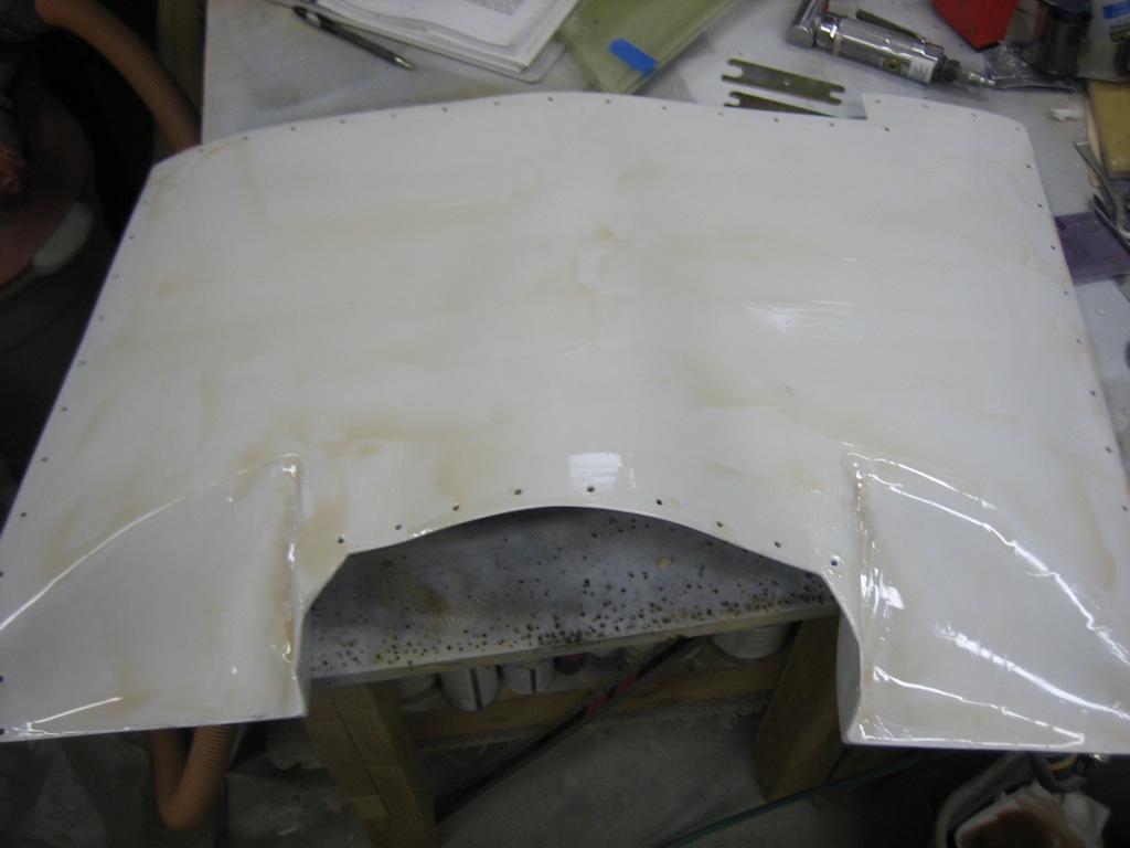
In addition to the bug which landed in my paint job, there were a bunch of scratches and pinholes visible in the finish.  Since this will be very visible with the cowl off, I decided to try out a new technique for surface finishing.  I sanded the surface with 80 grit and then spread raw epoxy over the surface.  After it kicked, I squeegeed as much off as I could and then spread on another coat.  After that kicked, I squeegeed it off as well.  That should fill all of the pinholes and scratches.  I’ll sand this with some finer grit sandpaper before reshooting the primer and finish coat.

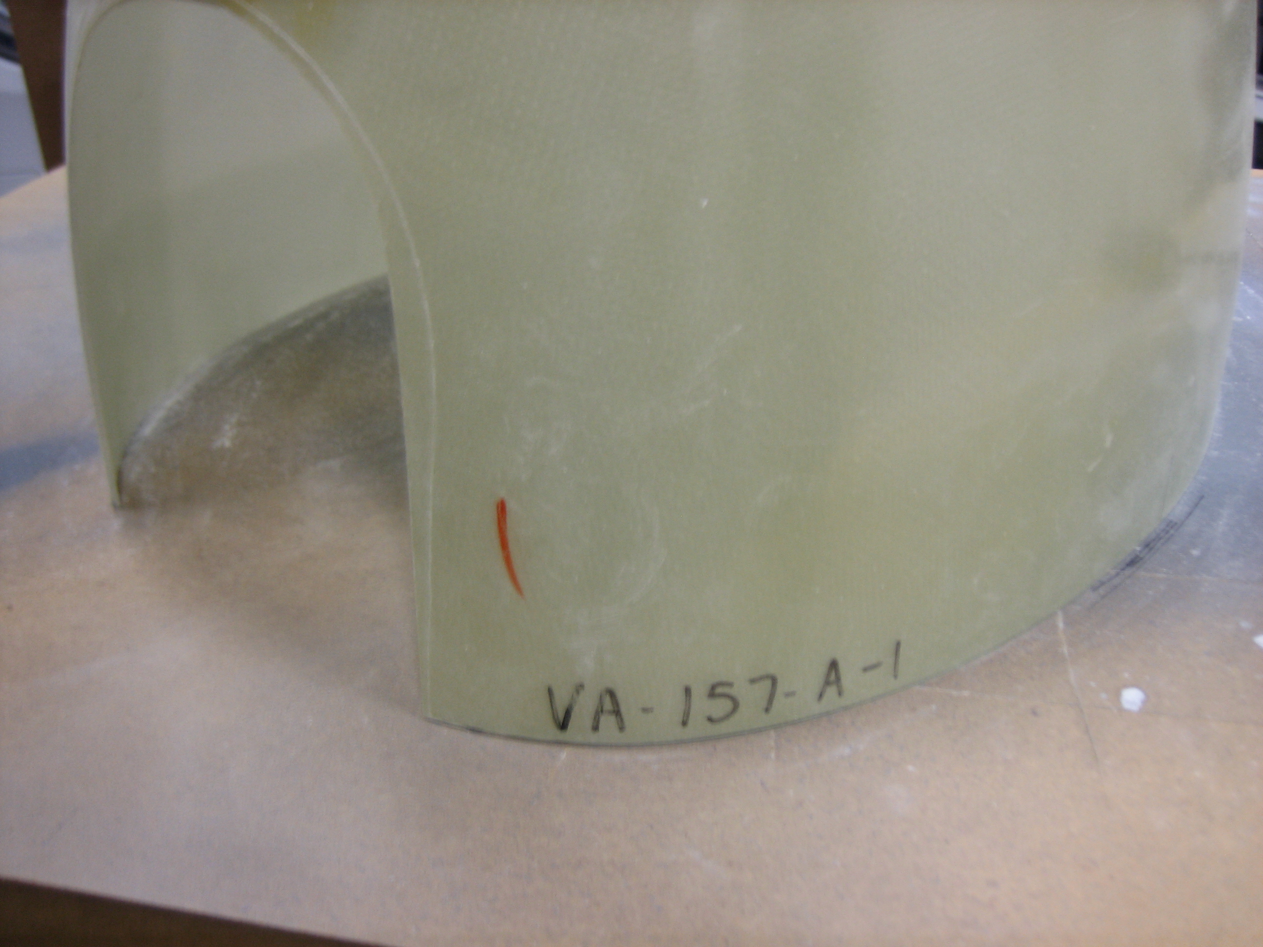
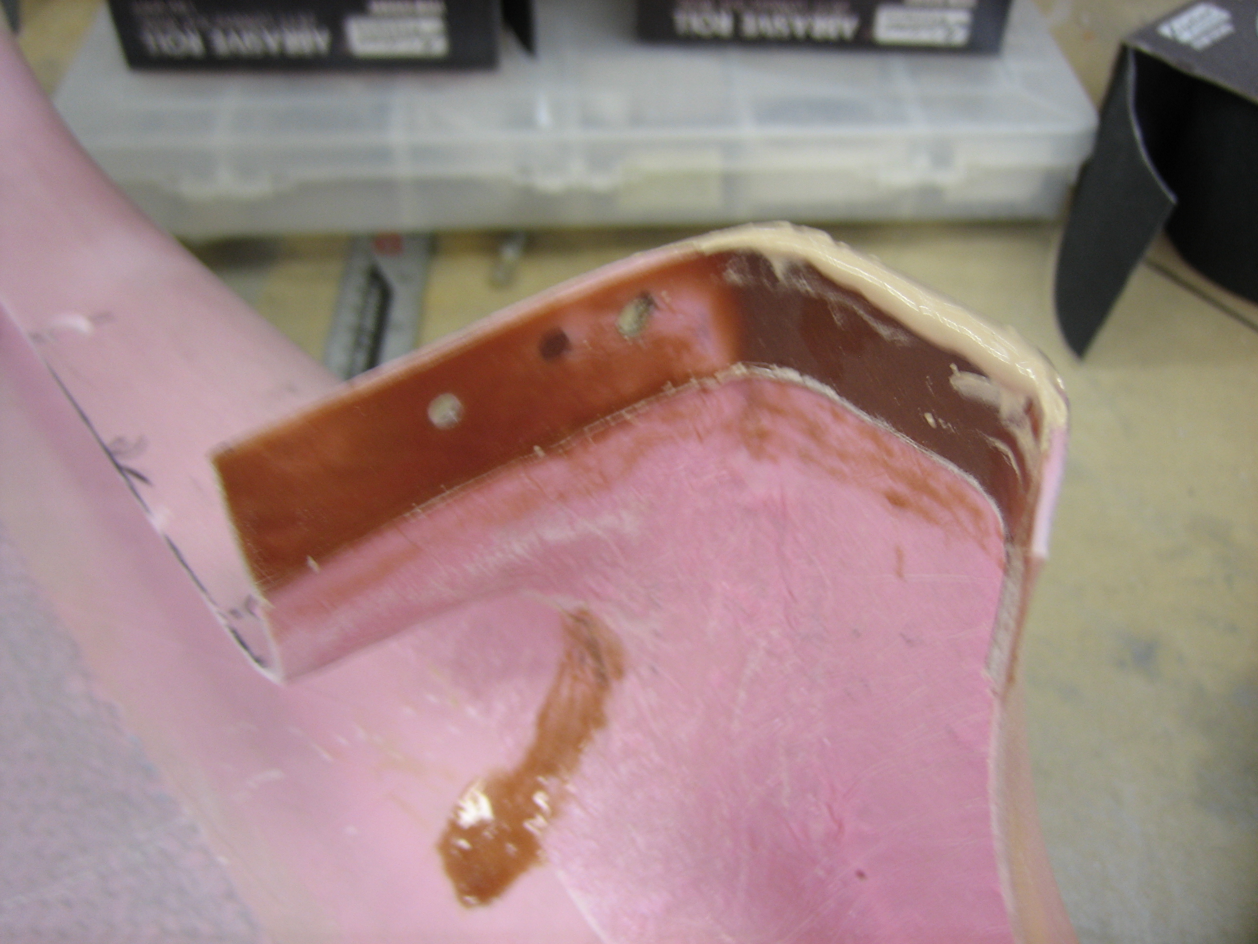
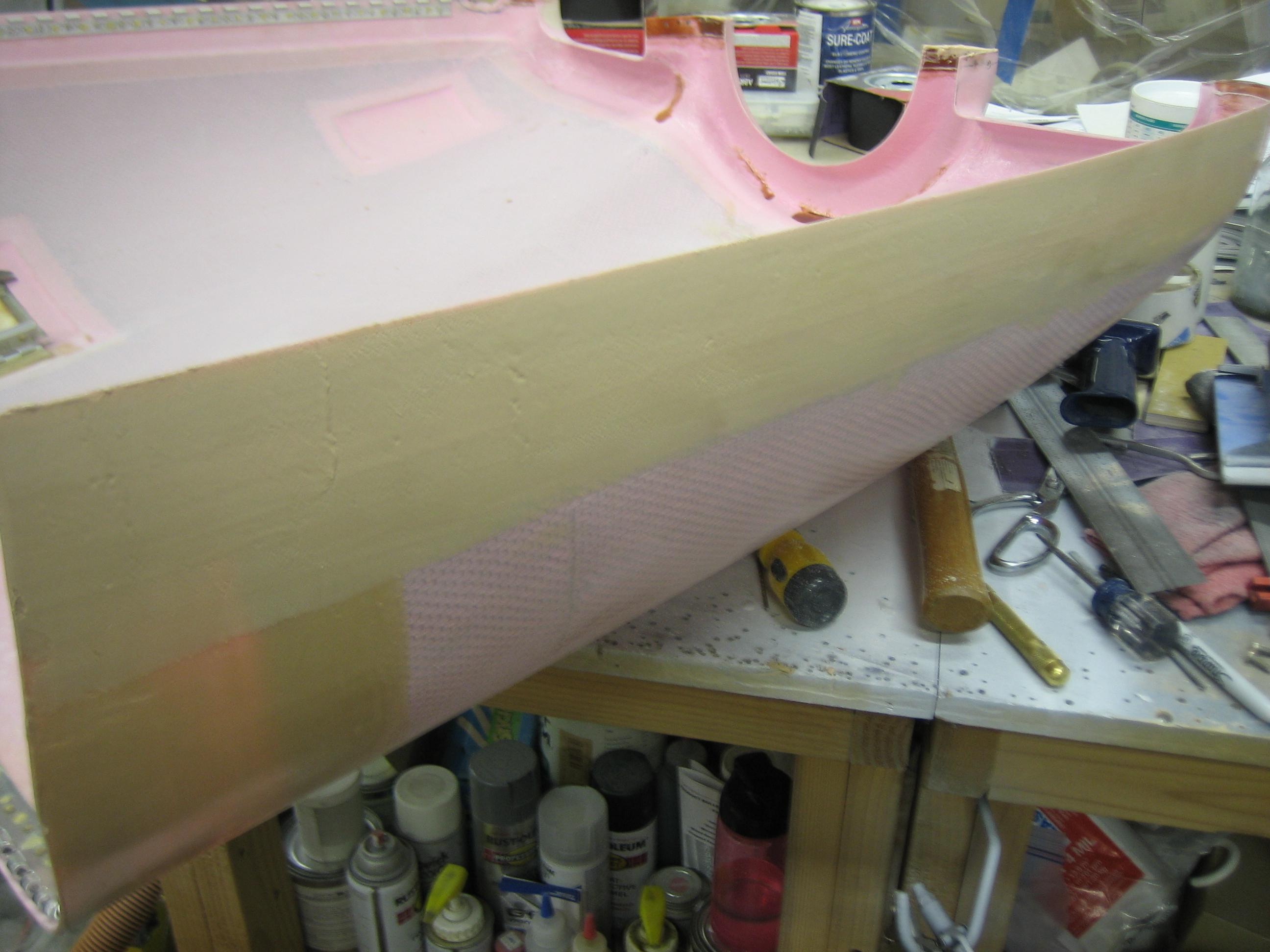
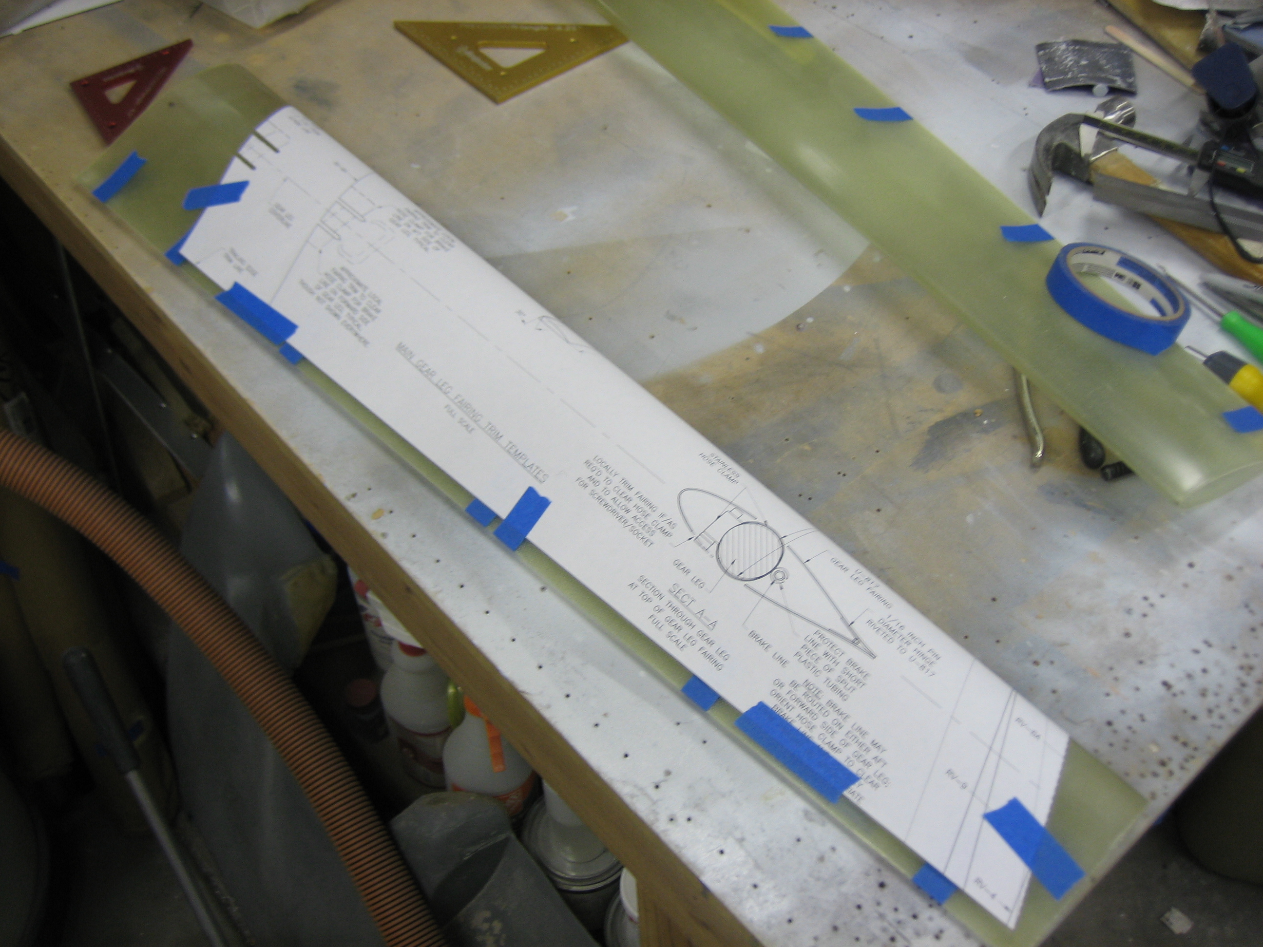
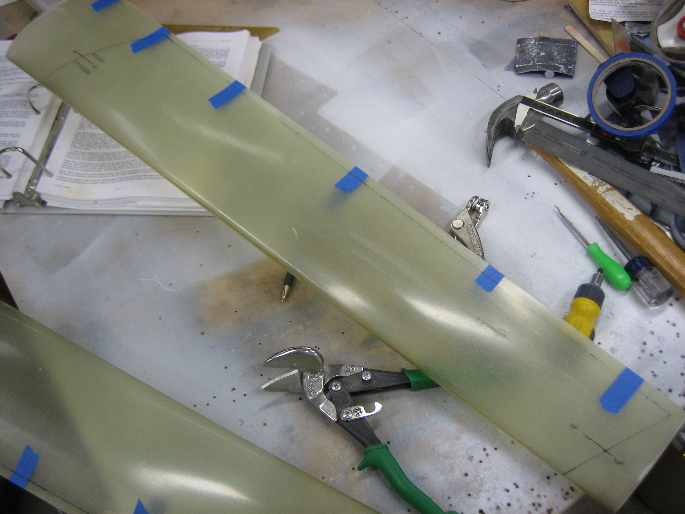
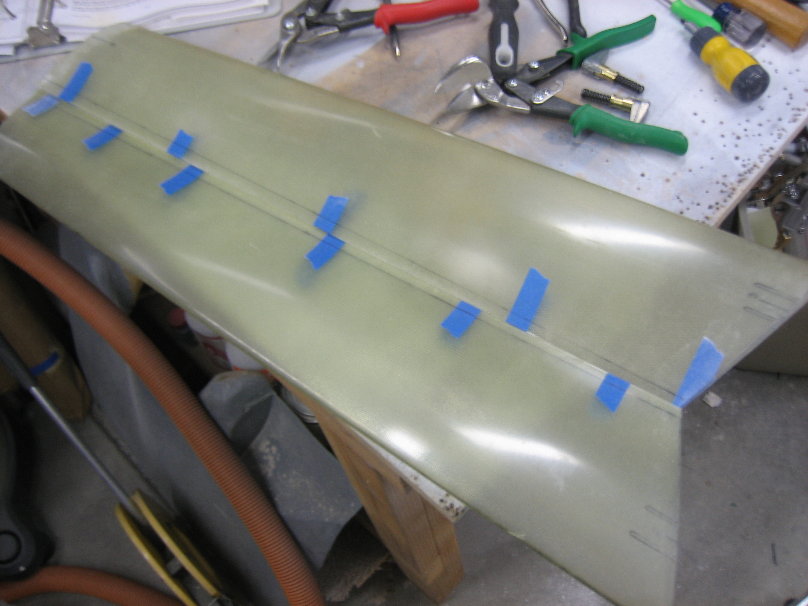
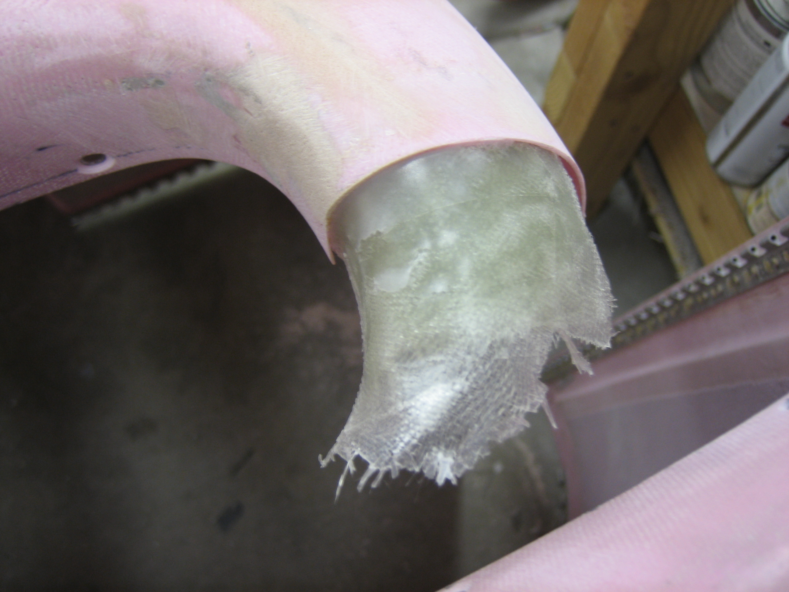
Between coats of raw epoxy on the plenum, I got started fitting the wheel pants.

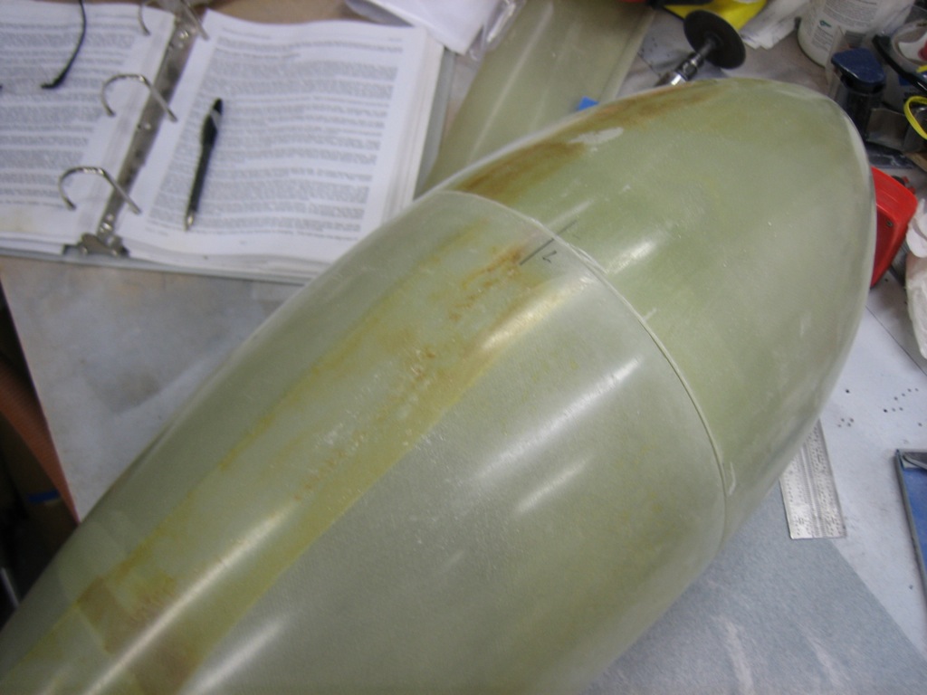
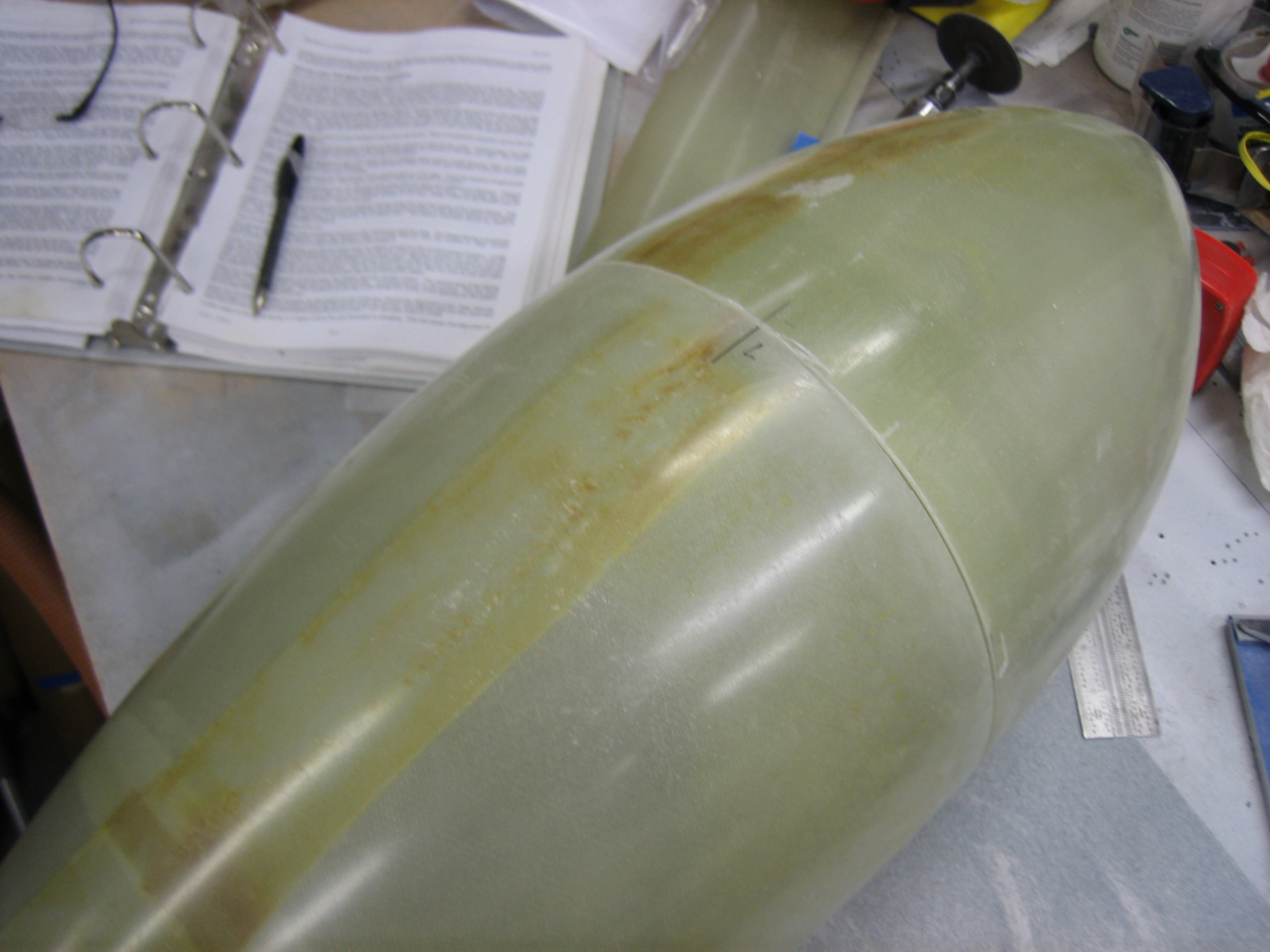
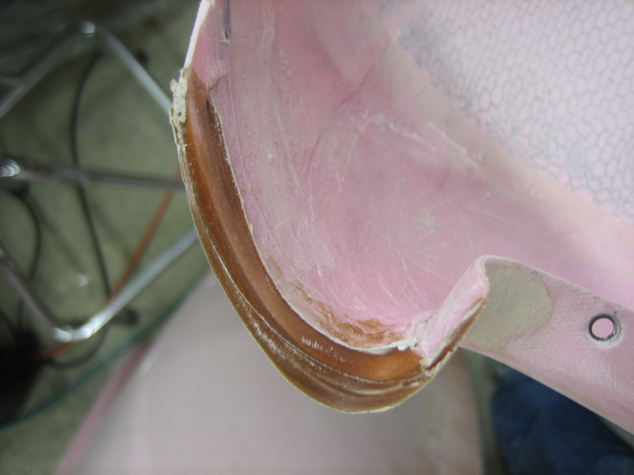
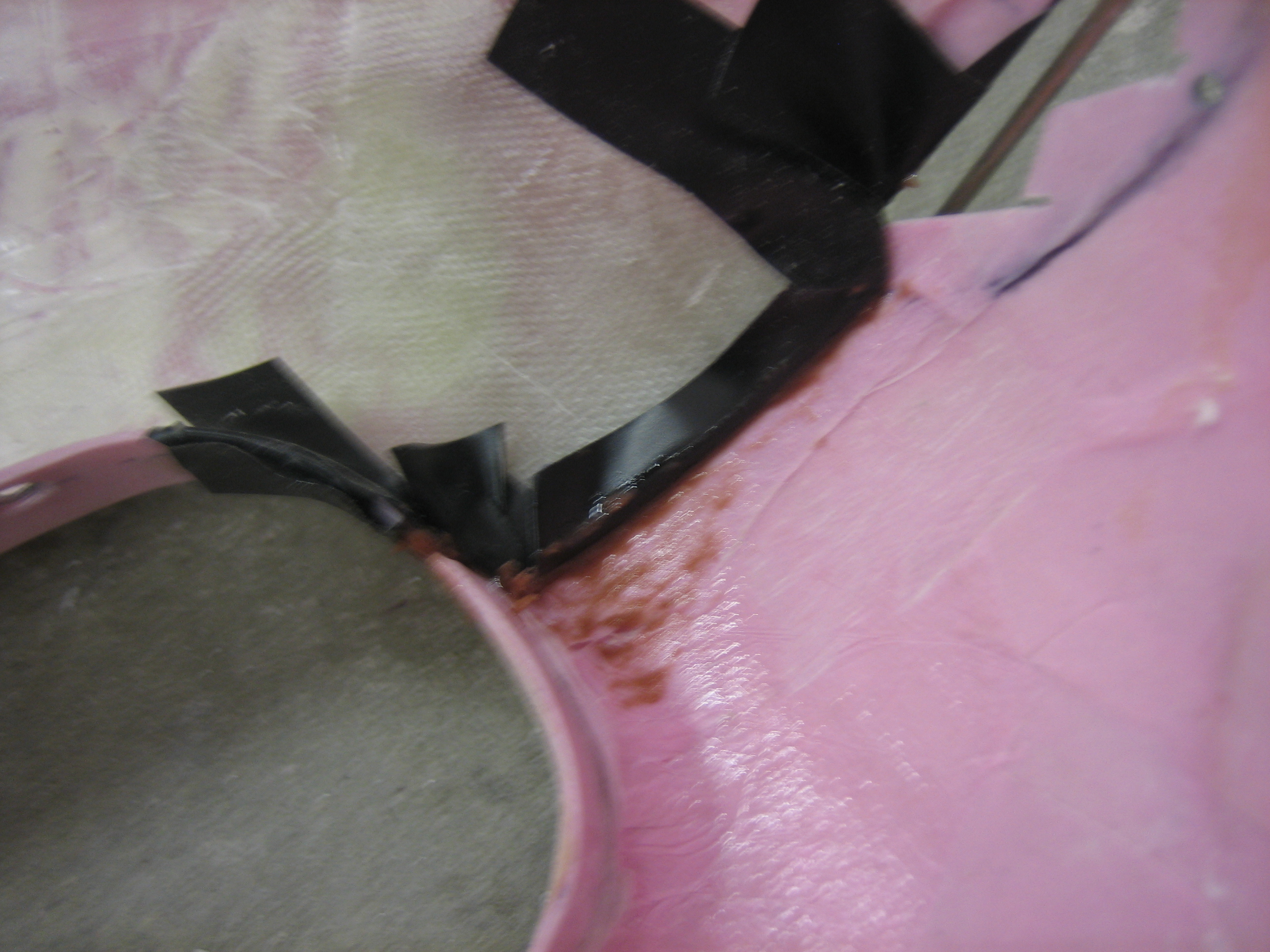
After figuring out where the two halves fit the best, I added some witness marks to make sure I put it back together the same way each time.

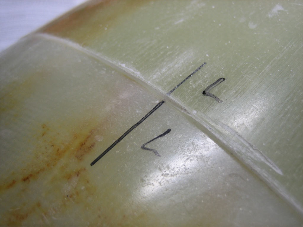
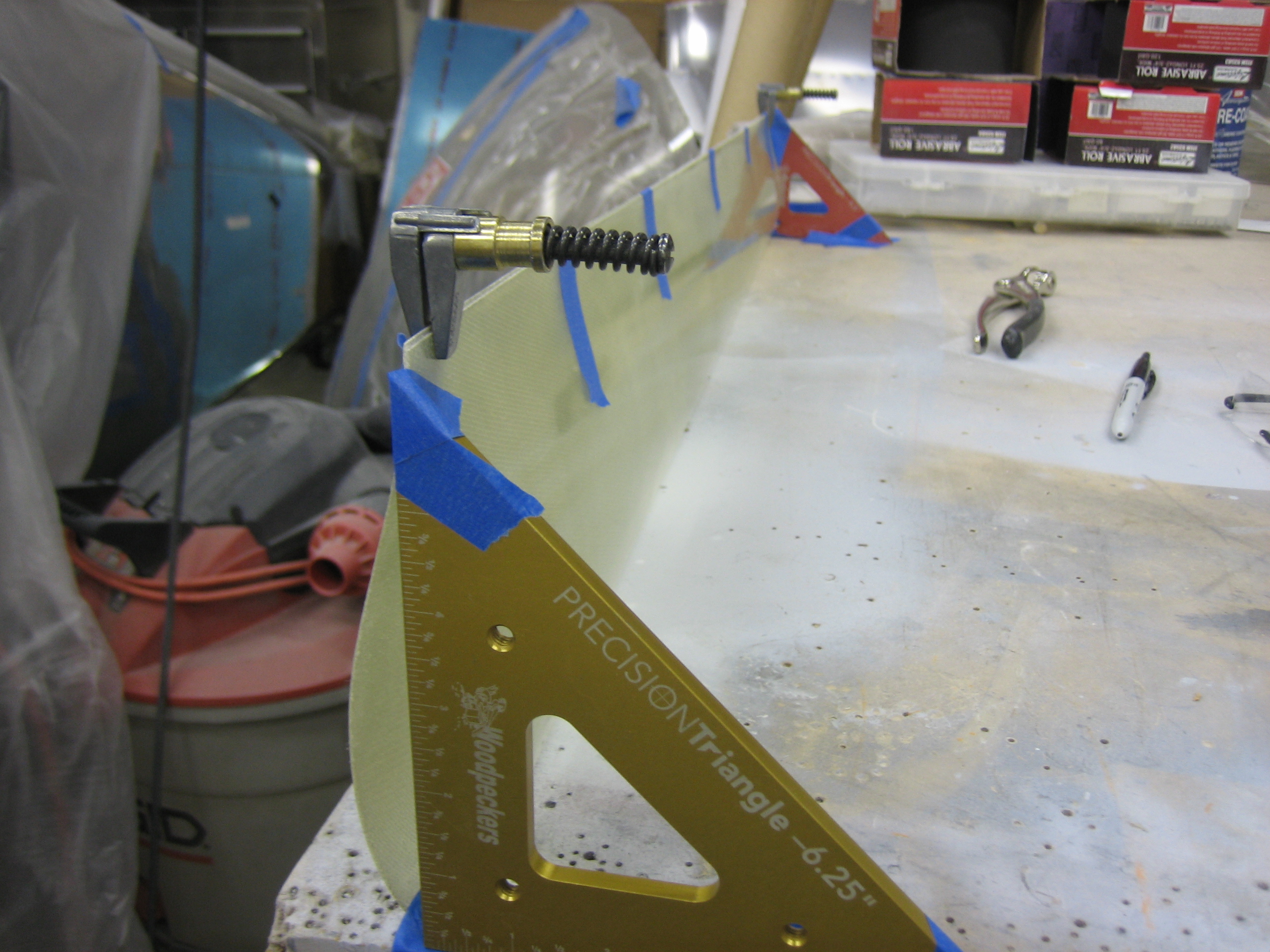
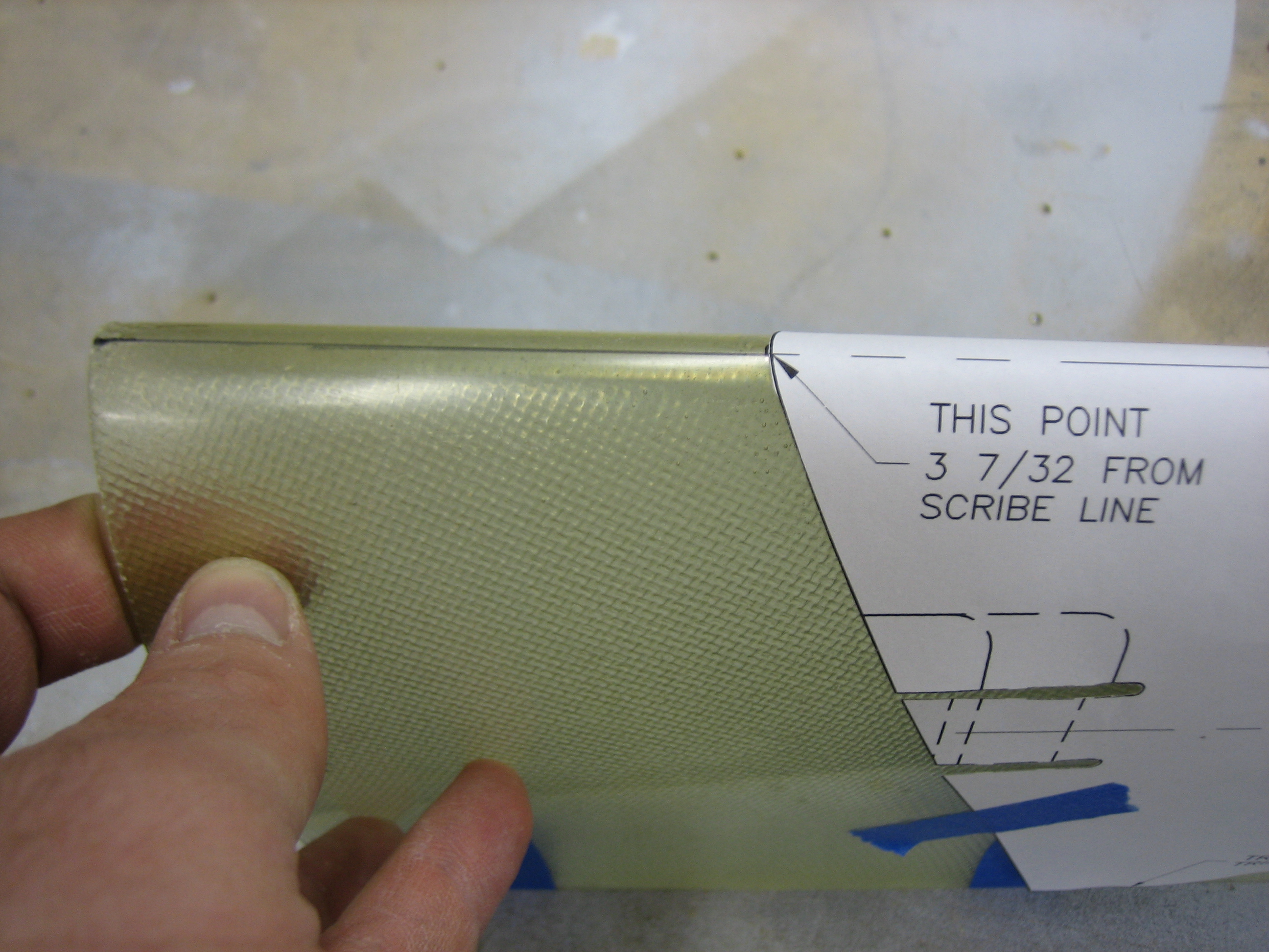
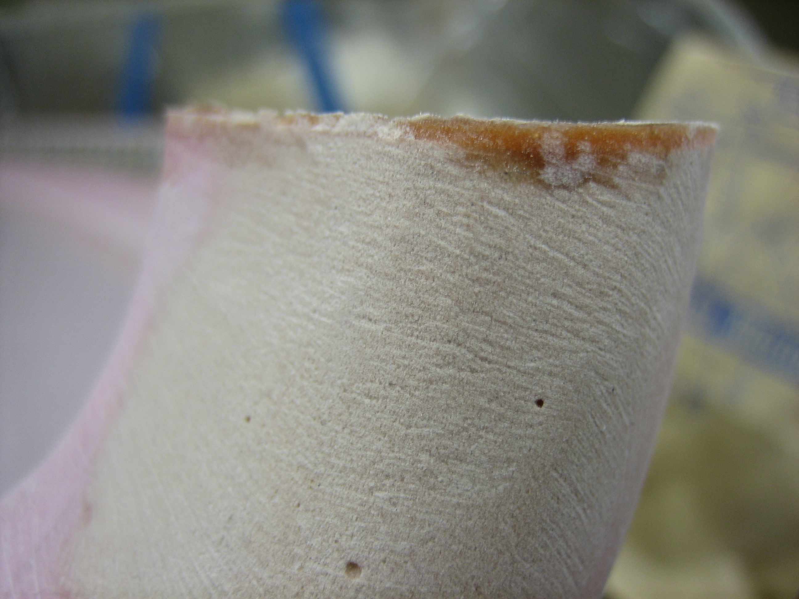
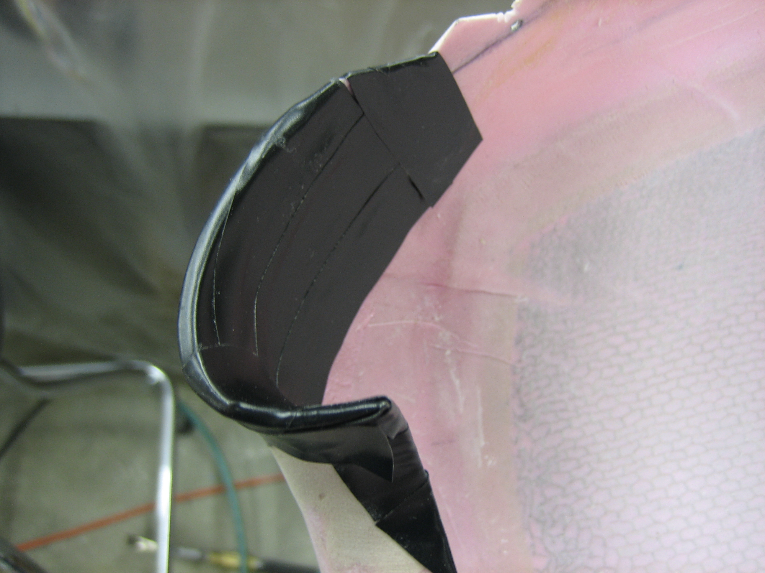
I trimmed the forward end to the scribe line and then sanded the edge until it sat flat on the table.  You have to spread the wheel pant slightly when checking because it naturally springs inward a bit.  It you sanded it flat in it’s rest state, the line wouldn’t be straight when installed on the aft half of the pant.

Fixed Propeller Ring Flange

The fit on the propeller ring has always been pretty poor.  Now that the upper cowl flange is straight and is a perfect fit for the shape of the lower flange, I can fix the position of the lower flange step to line up with the upper flange.  I assembled the two halves with a piece of saran wrap sandwiched between and then stretched it back over the upper flange.

I then mixed up some epoxy/micro and filled in the gap.  After it cured, I rough shaped it with a vixen file.  I still need to build up the face of the propeller flange a bit near the joint, so there’s no sense in making this perfect now, but you can already seen how much nicer this looks.  While this was curing, I cut and laid out the holes on the gear leg fairing hinges.

Installed Left Inboard Wheel Pant Bracket

I fabricated the spacers that position the inboard wheel pant bracket.  The plans call for 13/32″ (about 0.406″), but I have the Grove wheels and brakes which have a thicker brake rotor, so I ended up having to make them about 0.540″ in order to get the recommended 1/16″ clearance between the bracket and the rotor.  This is not the stock Van’s aluminum bracket, but is the fairings-etc.com stainless steel one.  While this is heavier than the stock bracket, there have been a number of instances of the stock bracket cracking due to rough fields or ground handling.  Hopefully these will be quite a bit more durable.

The bracket required about 1/4″ to be trimmed off where it passes over the caliper.  This has about 1/8″ clearance all around to allow the caliper to move.

Further Work on Cowl Joint, Started Gear Leg Fairings

I popped the two cowl halves apart again.  The epoxy/flox filler worked perfectly and there’s a nice smooth that perfectly matches the outside of the lower cowl.  The end of the flange was a little epoxy starved, so I mixed up some lightweight filler and buttered it up.  I’ll sand this flush tomorrow.

I had a bunch of excess lightweight filler left over, so I covered the last of the fiberglass strips on the left side of the upper cowl.

Since I need the filler to cure before making any more progress on the cowl, I decided to get started on the gear leg fairings. I lined up the fairing with a couple of squares to ensure there is absolutely no twist.  Any amount of twist is added drag, and can act like a rudder to yaw the plane.  After I was sure it had no twist, I taped the trailing edge together in a few spots.  This not only keeps it straight during the next couple of steps, but the tape strips will act as a indicator to ensure I don’t introduce any twist later.

I cut out the gear leg fairing template and lined it up with a line I drew on the leading edge, making sure to make the leading edge of the template 3 7/32 back from the scribe line.

I then taped up the rest of the template and marked all the way around.

Here’s the marked fairing.

After a few minutes with tin snips and a sanding block, here are the trimmed fairings.

Filled In Flanges Around Propeller Ring on Cowl

I popped the cowl apart from my filler application last night and this worked beautifully to make the flanges a perfect fit.

You can see here that it also allowed me to slightly extend the flange on the upper cowl to match up with the lower cowl.

Next up, I trimmed the upper and lower cowl flanges a bit and then wrapped the lower cowl flange with tape.  The electrical tape is there to define the line where the upper cowl flange should reach.  The packing tape is there to keep the epoxy from sticking to the lower cowl flange.

After assembling the cowl halves, I cleaned out the screw holes and punched a hole in the packing tape for the screw that aligns the two halves.  I waxed up the screw really well to keep the epoxy from sticking.

I then cleaned up the inside of the joint so there isn’t a bunch of excess epoxy here.

More Work on Cowl Flanges

I popped the two cowl halves apart and was left with a pretty nice flange.  I trimmed this down to about 1/4″ above the lip of the cowl.

I then taped it up, mixed up some epoxy/flox and reassembled the cowl.  This will provide a structural extension to the flange of the upper cowl (were there was a tiny gap between the top and bottom halves) as well as provide a perfect fit between the flange and the inside of the upper cowl.

Laid Up Flange on Outer Inlets

Where the upper and lower cowl halves meet on the outer ends of the inlets, the top and bottom sections simply butt together.  There is nothing tying the two parts of the cowl together at this point which allows some relative movement, and air entering through the gap is just added drag since it doesn’t help with engine cooling as it’s dumped directly into the low-pressure area outside the baffles.  To address this, I’m adding some flanges to the lower cowl that the upper cowl will nestle over.  This will reinforce this area a bit and seal the gap.  To prevent the epoxy from sticking to the upper cowl, I covered this area with electrical tape.  I would normally use packing tape, but it can’t conform to the curves like electrical tape can.

The lower cowl protruded beyond the upper cowl a small amount, so the glass wouldn’t have laid flat across the transition.  To fill in that step, I mixed up some epoxy/flox and made a small fillet.

I then laid up about 6 layers of glass across the joint.  I’ll trim this back quite a bit after it cures.  It really only needs to stick up into the upper cowl 1/2″ or so.

Here’s the other side.  You can see better here that the glass overlays the oval where the hinge pin covers will mount, so I’ll end up cutting back part of the flange to make room for the cover.