Added Additional Snorkel Attach Screw

I got back from Oshkosh a few days ago.  I flew with the Bonanzas to Oshkosh group in a buddy’s A36.  The show was great and the flight out there and back was a hell of a lot faster than our flight in the Cardinal a few years ago.  I thought I was done with the major purchases, but Dynon announced a new ADS-B receiver that will ship this fall, so I need to find a spot for that in the plane.

I’m waiting on some hardware to wrap up the propeller governor control cable, so I decided to try wrapping up the snorkel to baffle intersection.  The aft and outer snorkel flanges each have three screws, but the inner only had two.  At the forward end of the inner side, the bracket that ties the baffle floor to the wall surrounding the flywheel was right where the third screw would go.  After taking some measurements, it looked like the forward rivet hole would be fine for an additional screw.  I dimpled the aft hole for a flush rivet (flush on the bottom) and then dimpled the forward hole the other way for a #8 screw.

I had to grind away most of the edge of a K1100-08 nutplate to clear the bend in the flange, but this screw tightened up the forward end of the snorkel to baffle connection noticeably.  I now just need to trim the cowl to clear the front edge of the snorkel.

Fabricated Prop Governor Control Cable Attach Bracket

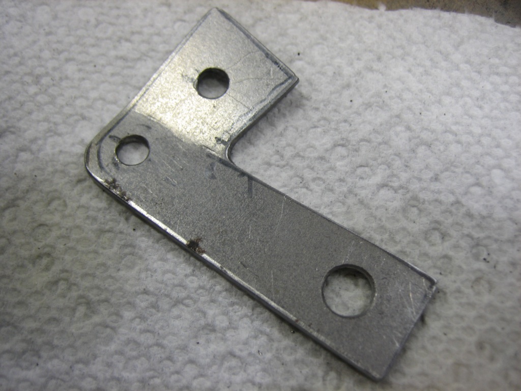
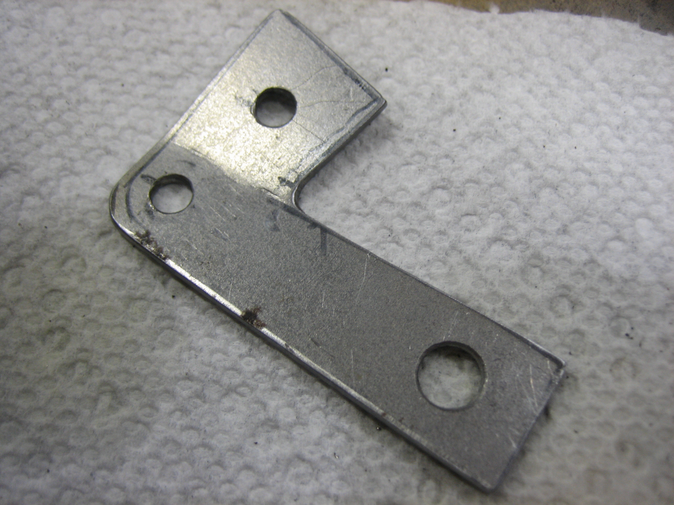
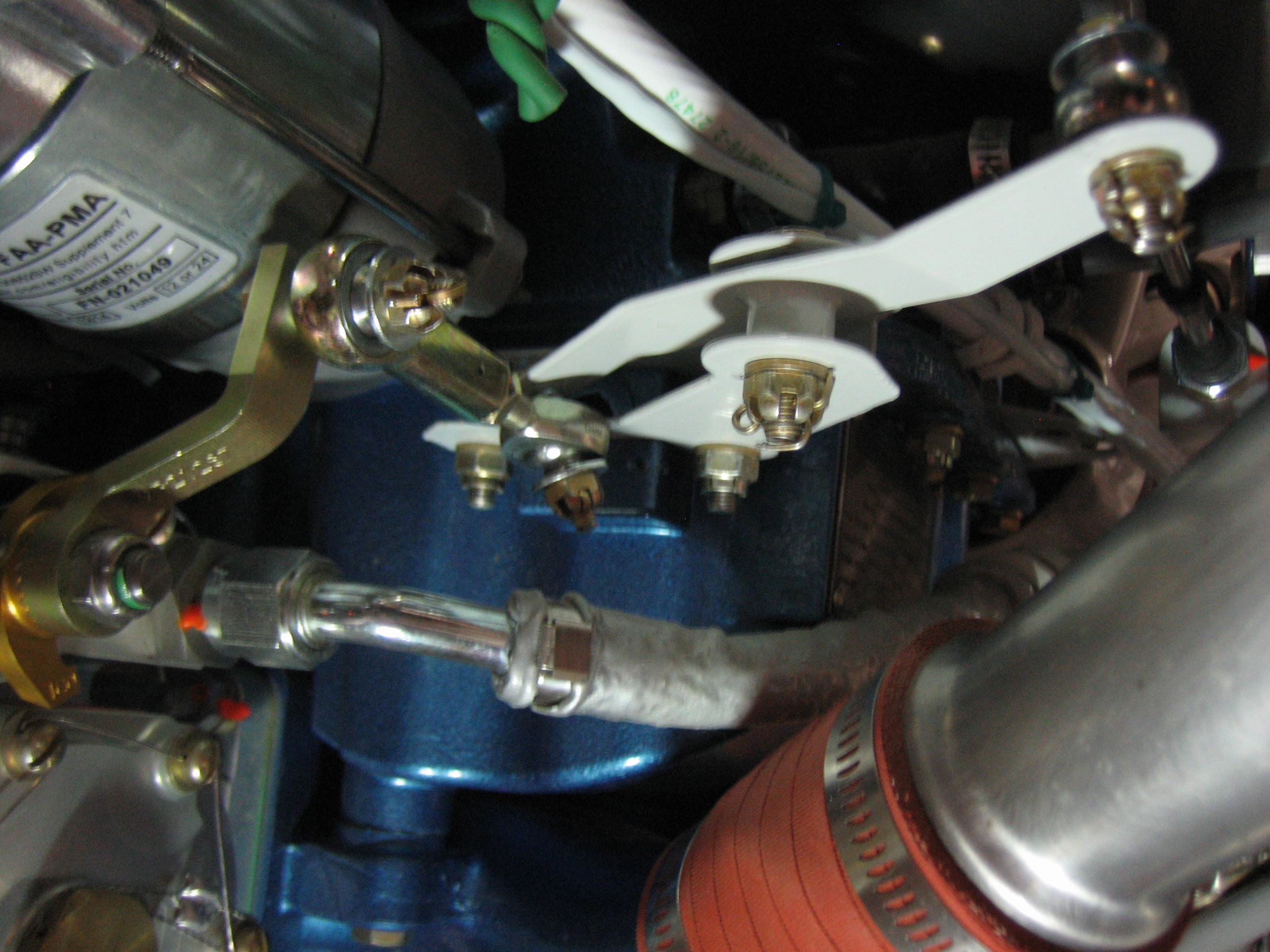
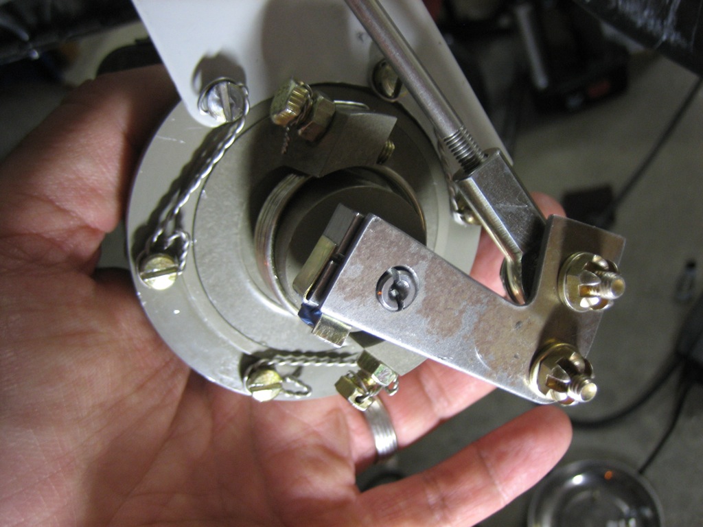
I’ve been trying to decide how I’m going to attach the prop governor control cable rod end bearing to the prop governor arm.  The issue is that the rod end bearing has to be installed with various washers to allow the bearing to have some freedom of movement and some protection in case the bearing fails.  This requires an AN3-11 bolt which is too long to insert from the front side of the arm (between the governor and the arm). Reversing the bolt and installing it from the aft side doesn’t work either because the bolt ends up hitting one of the screws around the perimeter of the governor head.  Van’s specifies an AN3-10A bolt, but that’s still too long and I really don’t think it’s a good idea to use a self-locking nut anywhere related to the engine control cables.  I spoke with John DeJoris at Aircraft Propeller about this issue, and he suggested using one of their adaptor brackets.  None of their stock ones looked like it would work, but it gave me a great idea how to make one.  I fabricated this little bracket from some 16g sheet steel.  It still needs to be cleaned up and powder coated, but this is how it will be installed.  There is a 1/4″ hole that fits over the center shaft to prevent the bracket from shifting.  It’s attached to the arm at the end with a short bolt and castellated nut.  There is a flange that sticks out and has an extra hole for the bolt that attaches the control cable.  This hole is positioned 1.5″ from the pivot point just like the hole in the arm, so the cable throw is identical.  Since this offsets the attach point from the arm, I needed to turn the control head to allow the arm to be moved through the whole range.  While this could probably have been done with the governor on the engine, I decided to pull it off and do the adjustment on the bench.  I’m really glad I did too.  It was pretty trivial to pull and replace, and it was far easier redoing all of this safety wire on the bench.

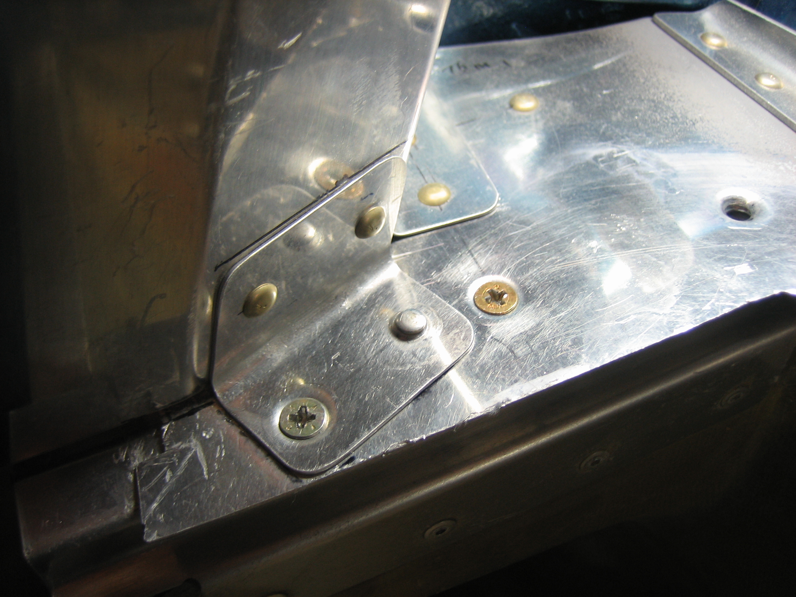
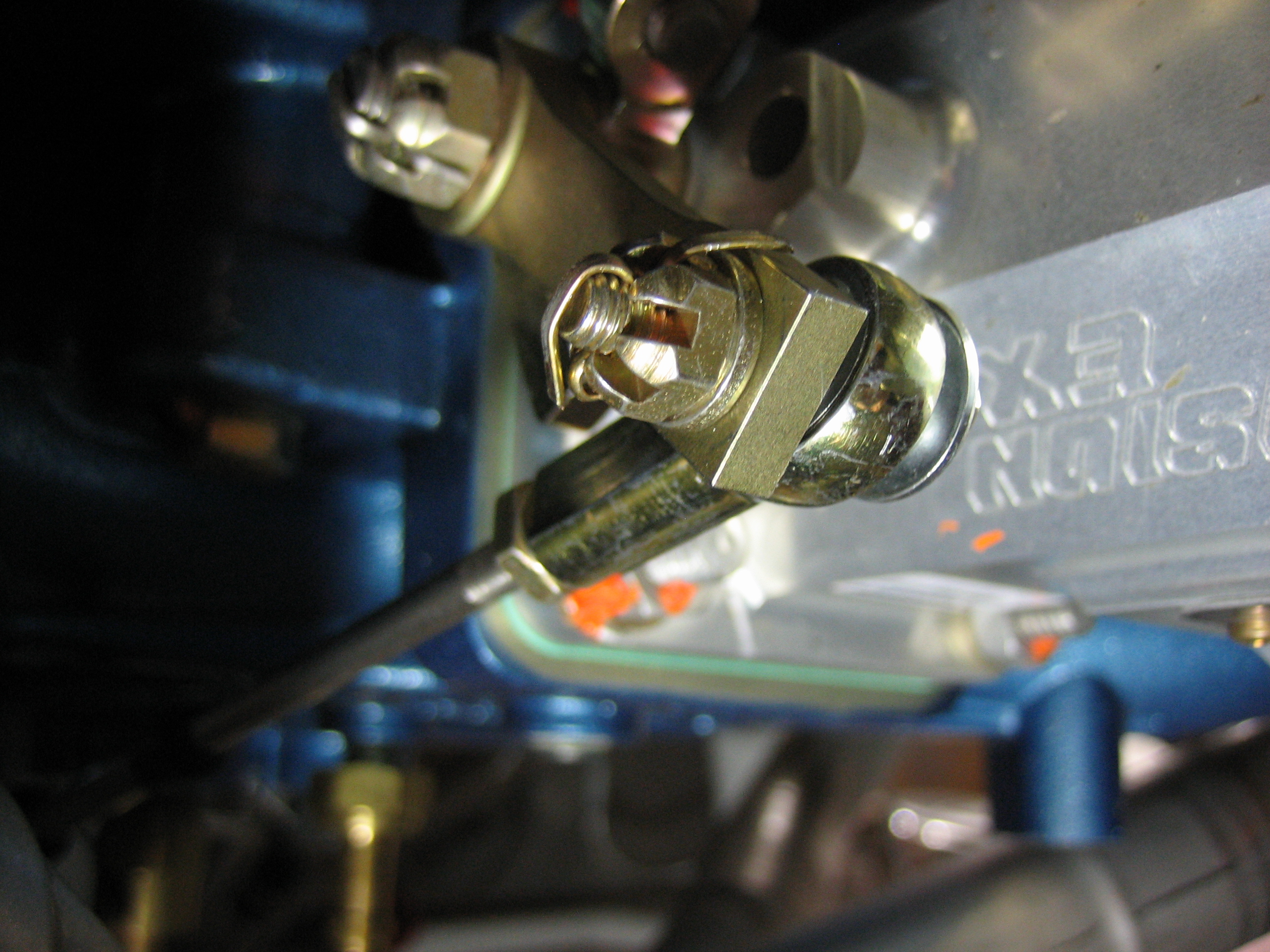
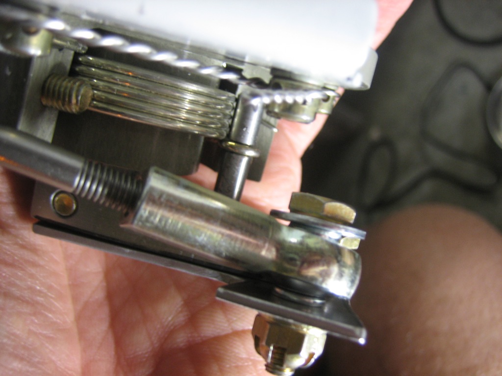
Here you can see that the bracket has a bend in it so that the rod end bearing doesn’t attach at such a steep angle (ignore the bearing alignment here; I hadn’t installed the jam nut to keep it from twisting).

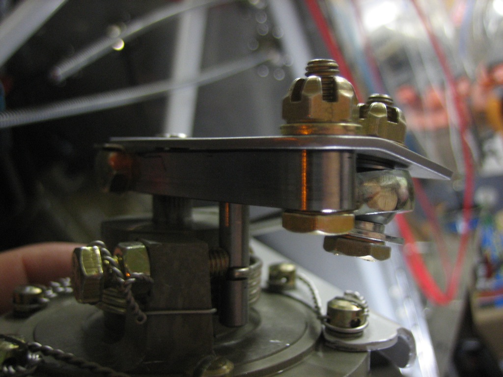
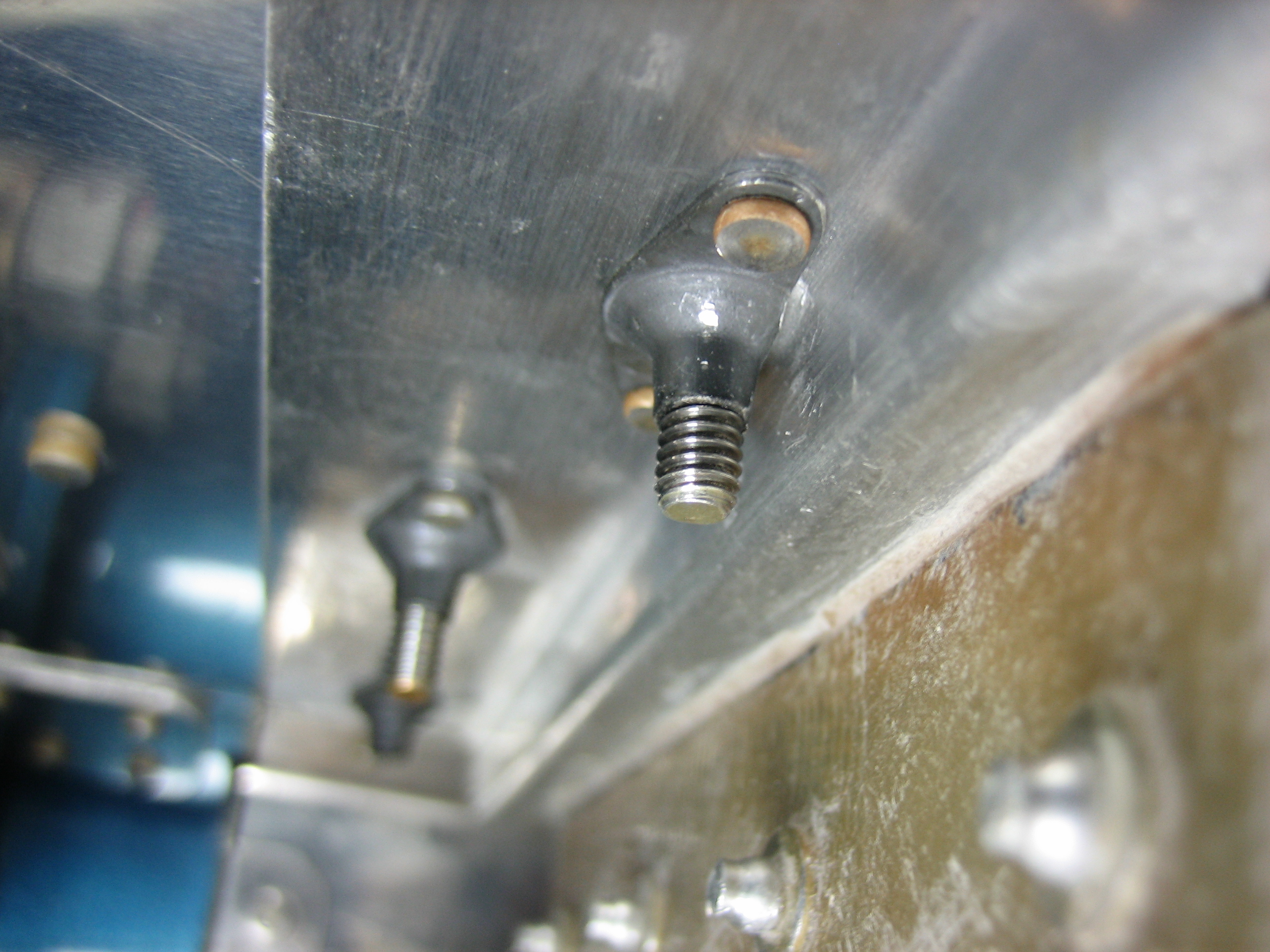
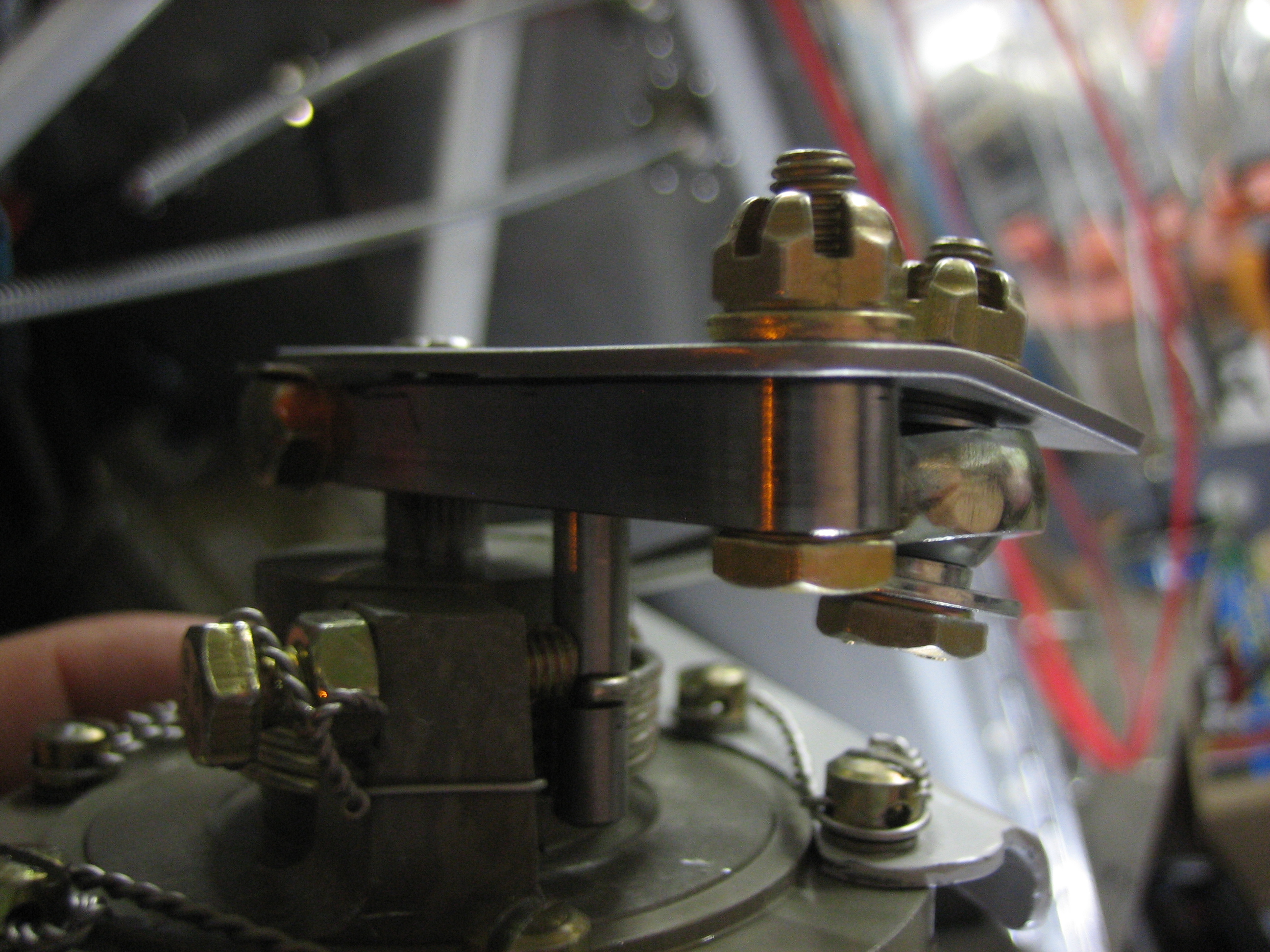
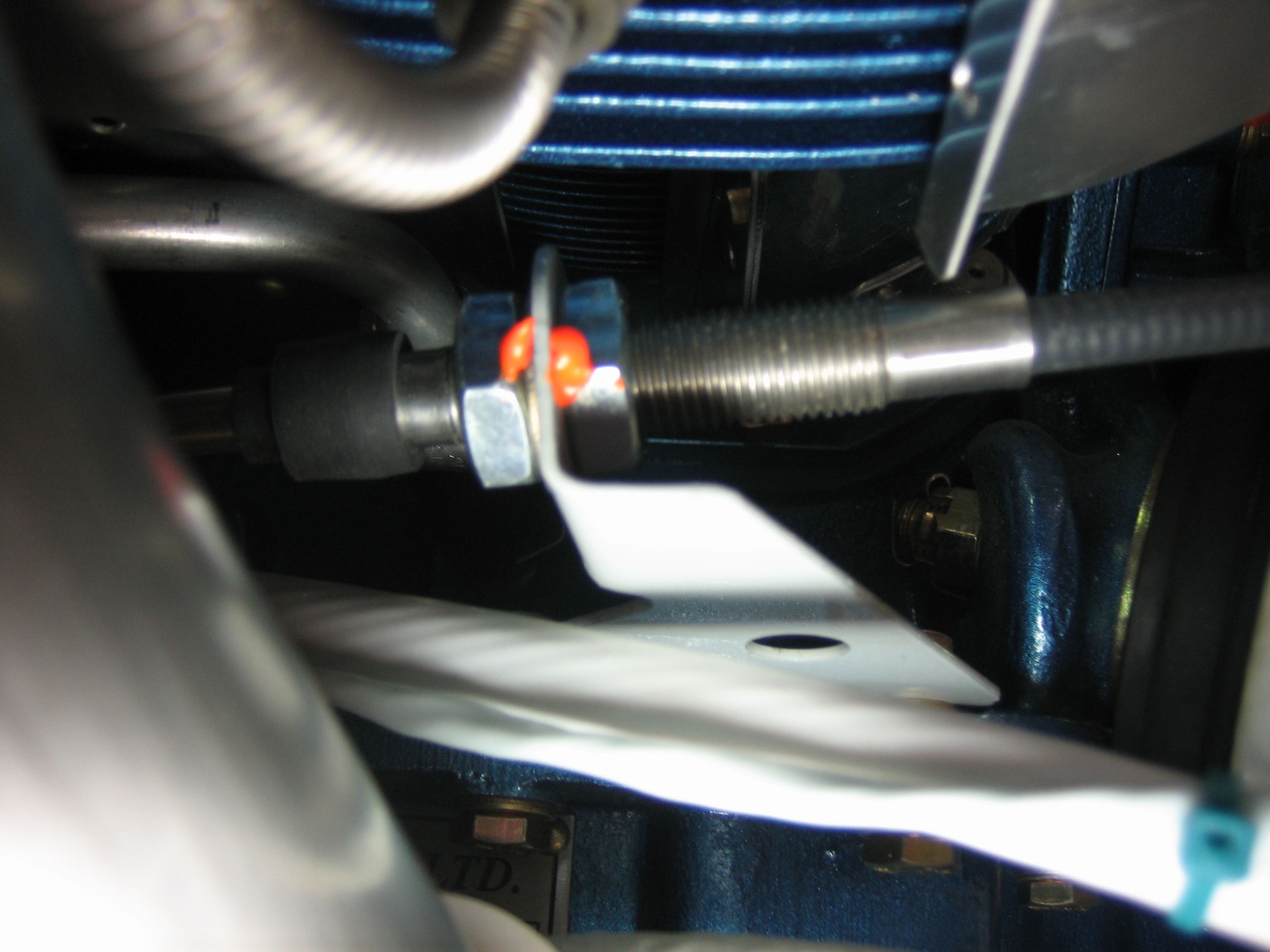
Here’s a good shot of how much better the bearing alignment is with that bend.

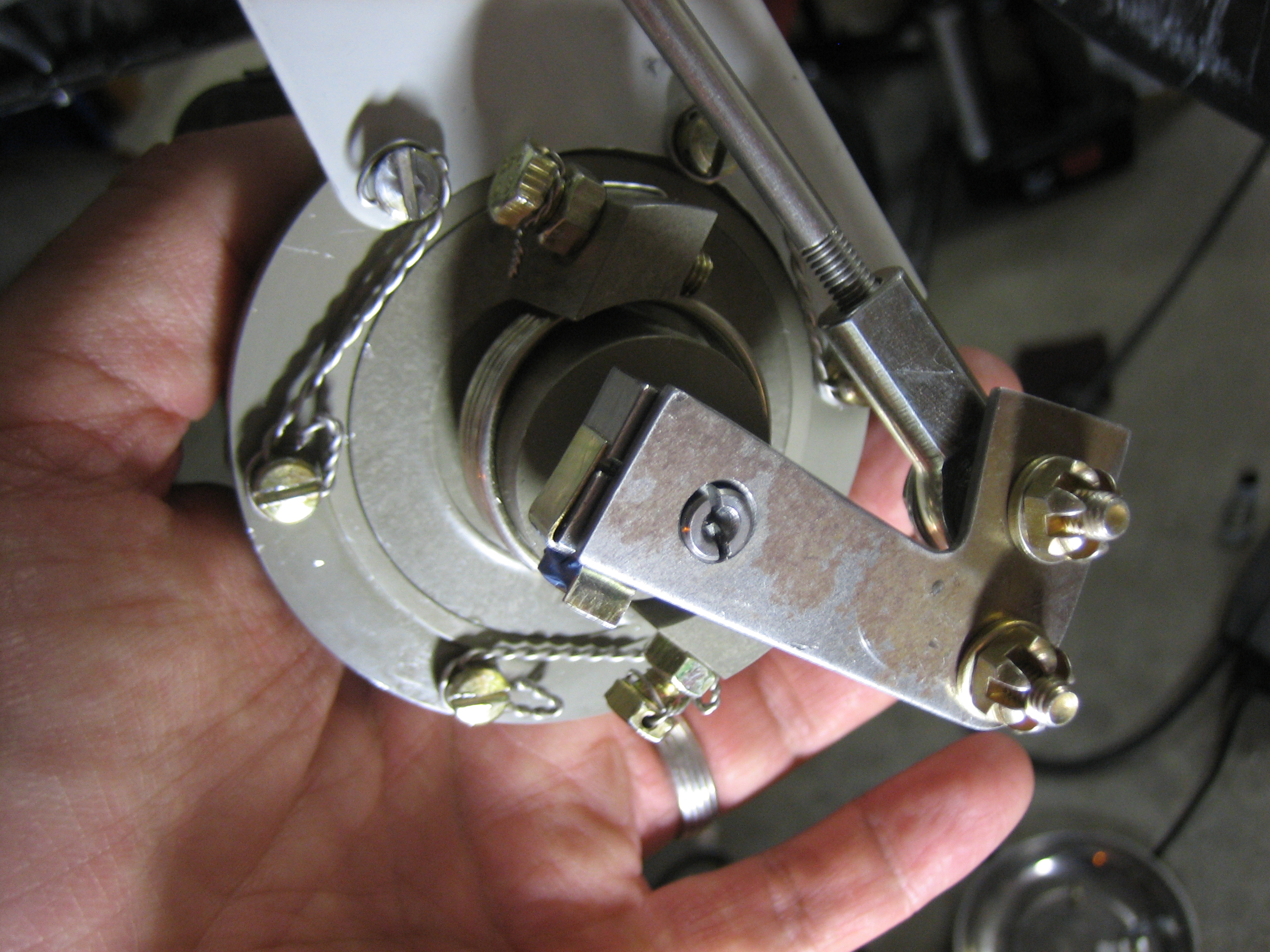
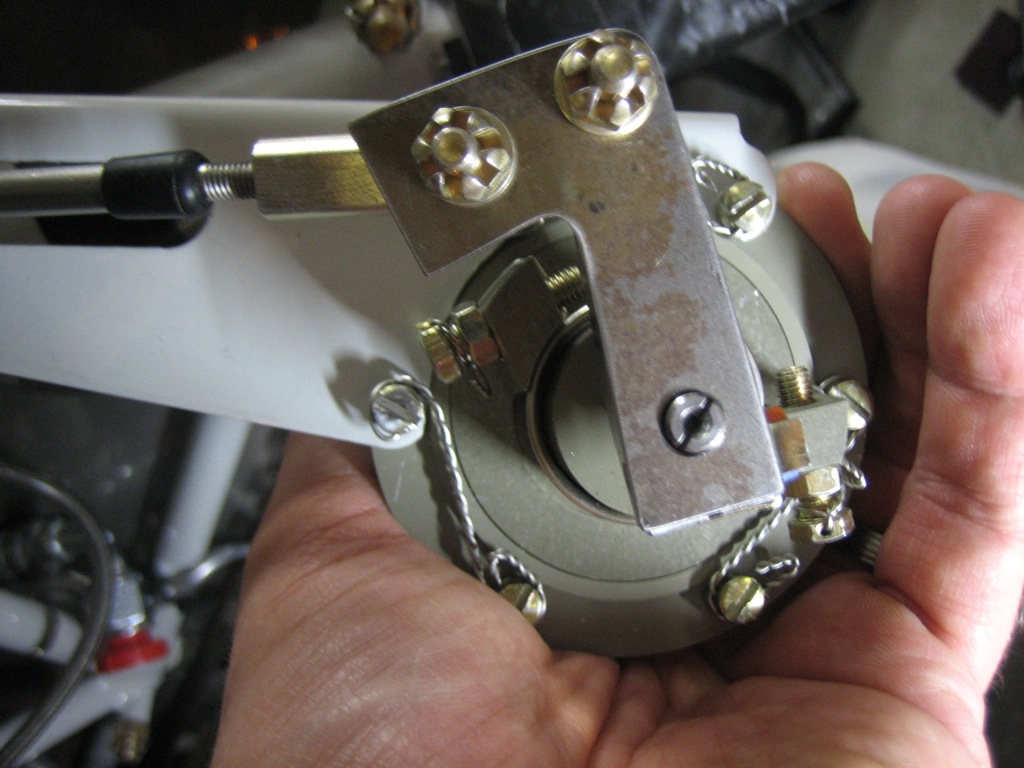
Here’s the control arm at the fine pitch stop.  You can see the arm is a lot farther around (clockwise) than would work if the cable attached directly to the arm.

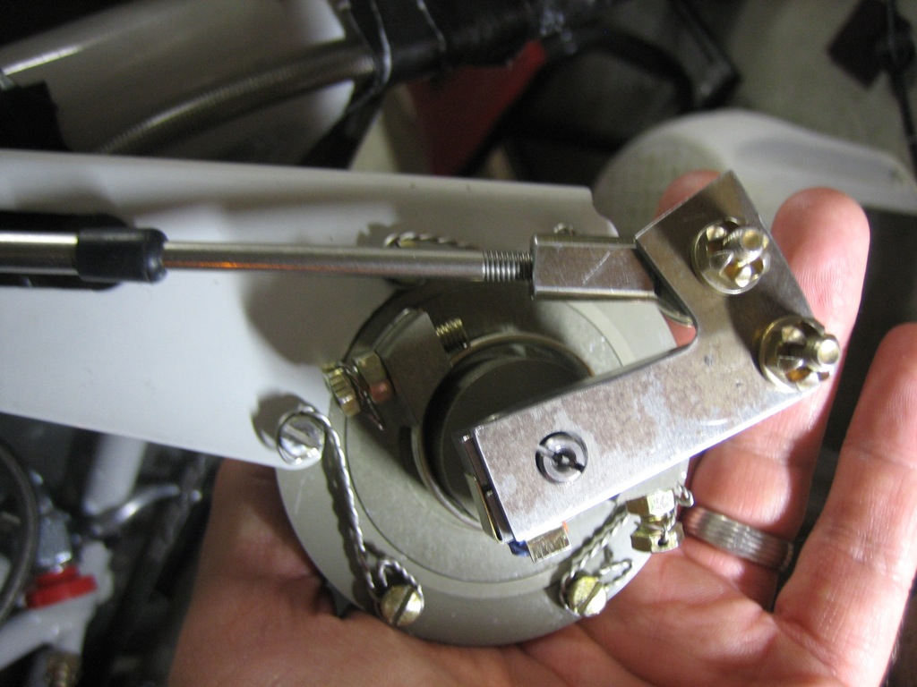
Here’s the control arm at the coarse pitch stop.  You can tell from the last picture and this one that the overall throw is biased towards the fine pitch stop.  This works beautifully because you’re pulling against a spring as you move towards the coarse pitch stop, but you’re gaining mechanical advantage as you pull because the cable and arm become more perpendicular.  This means that the pull feels pretty linear.  When I had the throw more evenly spread, the control cable required a fairly hard pull near the end to get the arm near the coarse pitch stop because you lost mechanical advantage and the spring force was the strongest.

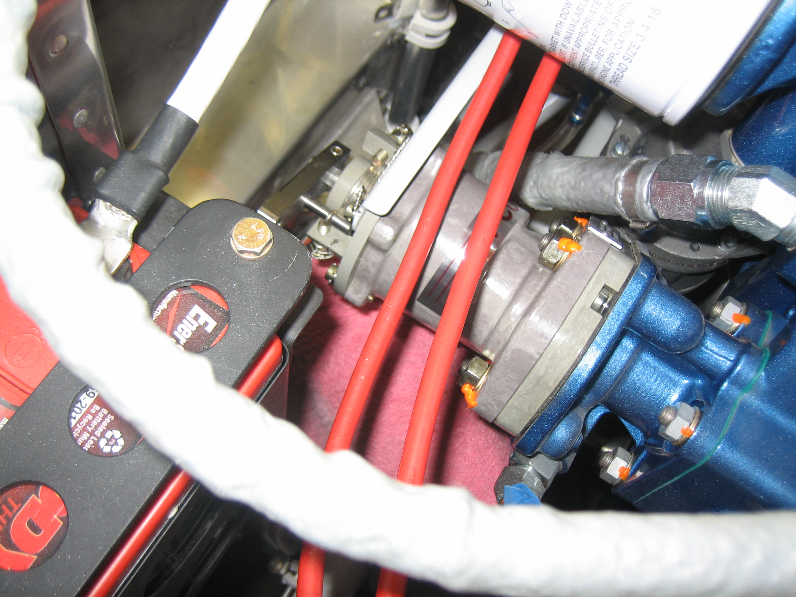
After getting everything adjusted, I reinstalled the governor with new washers and lock washers, and then torqued/sealed the attach nuts.

Here’s the finished bracket.  All it needs now is some cleanup and powder coating.

Fabricated Front Air Filter Support Angle

I fabricated the front air filter support angle tonight.  This is fabricated out of 0.063″ angle since it will only sit below the flange of the air filter and won’t wrap all the way around the edge and screw to the bottom of the baffles.  Using the thicker angle allows it to remain stiff enough to support the flange of the air filter.  I’m going to cut it off at the black line which is aligned with the edge of the air filter.  I’ll have to trim the inlet to the cowl back a bit to provide enough clearance to allow it to be installed.

Received Extra SkyView Mounting Screw

In the process of installing the SkyView displays the other day, I stripped the heads of several screws.  I even had to drill out two of them because I couldn’t back them out.  The problem is that these screws use a really small allen head wrench but I was driving them into #6 nutplates which are designed to grip the screw really tightly to prevent it from backing out.  I mostly tapped out the nutplates to reduce the grip and installed the remaining unstripped screws.  The next day I called Dynon and asked if they could send me a few extra screws, and they ended up sending me a lifetime supply!  Thanks to Steve and the other guys at Dynon; you guys rock!

Installed Parking Brake and Cabin Heat Control Cables

I reinstalled the parking brake cable and all of the adel clamps that secure it.

Here’s the valve end.  Removing this adel clamp requires removing the electronic ignition box.  Hopefully, I won’t have to do that much.

The cabin heat control cable arcs over the rudder pedal torque tubes and is anchored to one of the firewall stiffeners before heading towards the center of the cabin.

The end of the cable housing is anchored with another adel clamp using the bolt that attaches the heater box.

Started Installing Control Cables

I started wrapping up the control cable installation tonight.  First up is the cable supports on the subpanel.  Attaching these stiffened up the control bracket quite a bit, but there’s still a bit of flex.  I may add a stiffener between the control bracket and the subpanel.

This is the forward end of the control cable.  I replaced the undrilled bolt with all metal lock nut that is specified in the plans with a drilled bolt, castellated nut, and cotter pin.  I’m doing that on all bolts used in the engine control cables.

Here’s the forward end of the throttle cable.  All adjustment nuts have been torqued and sealed.

Here’s the firewall penetration for the throttle cable.  This is installed for good.

Here’s the finished attach end of the mixture control cable.  All linkages have been adjusted and cotter-pinned.

I had to adjust the bracket attach on the control cable to the far forward end of the threads.

The mixture cable firewall penetration on the left is done.  The prop governor penetration on the right is still loose until I get everything adjusted.

Finished Instrument Panel

I installed the SkyView screens and radio stack and fired up the panel to make sure everything was working properly.

Next, I installed the control cables in the bracket and attached that to the bottom of the instrument panel.

I didn’t get a shot of this last night, but here’s the back of the Gemini PFD.  I still need to install a DB-9 connector shell, but this shot shows the pitot and static connections.  The green tubing is the pitot and the white tubing is the static.  This has to tee to go up to the alt static switch.

Here’s the alt static switch.  This opens the static tubing up to cabin pressure.

To wrap up the panel, I put switch boots on most of the switches.  All of these are marked red because switching any of them in flight could be critical.

All light switches are blue.  Here are the exterior lights.

The interior lights both have dimmers.  Here are the controls for the cabin lights which are mounted in the roll bar support.

Here are the glare shield lights.

The fuel pump and flaps have yellow boots because operating them should be done with caution.

Here are the completed seat heater controls.  The cabin heat control is just to the right.

Started Reinstalling Panel

I shot some matte clear over the panel and let it cure for a couple of hours.  I then installed the panel and started installing components.  I got everything but the SkyView displays and radio stack installed for good.

I already ran all the wires for the TruTrak Gemini PFD, so I quickly wired it up and hooked up the pitot and static tubes.  I then reconnected the battery and turned on the avionics to check it out.  I still need to figure out the screen dimming, but that shouldn’t take too long.

Finished Labeling Panel

I finished labeling the panel today since we were off work for the 4th and my wife had to work all day.  Here’s an overall shot.

In the lower left, there are two spots for control cables to control the alt air and the oil cooler butterfly valve.  To the right of that are the exterior lights.

To the right of the exterior lights are two separate groups of interior lights.  Each can be set to either white or green light and has a dimmer.  Finally, the fuel pump and flaps switches round out the row.

The engine controls and parking brake labels are on the main panel since I shortened the height of the control bracket.

At the top of the radio stack are the test button for the annunciator lights and the dimmer which will dim both the annunciator lights and the TruTrak Gemini PFD (which unfortunately doesn’t have a light sensor and self-dimming capability).

Above the pilot’s PFD is the tail number.

On the lower right of the panel is the controls for the seat heaters and cabin heat.

The top right has the only two breakers in the plane, pullable units for the electronic ignition and autopilot servos.

Above the copilot’s display is the RV-7 badge in the Zapfino font using a silver holographic foil.  The picture really can’t capture how this looks, but the color changes depending on the angle you view this from.  This would look tacky if you used too much of it, but it looks really sweet on just this one detail.