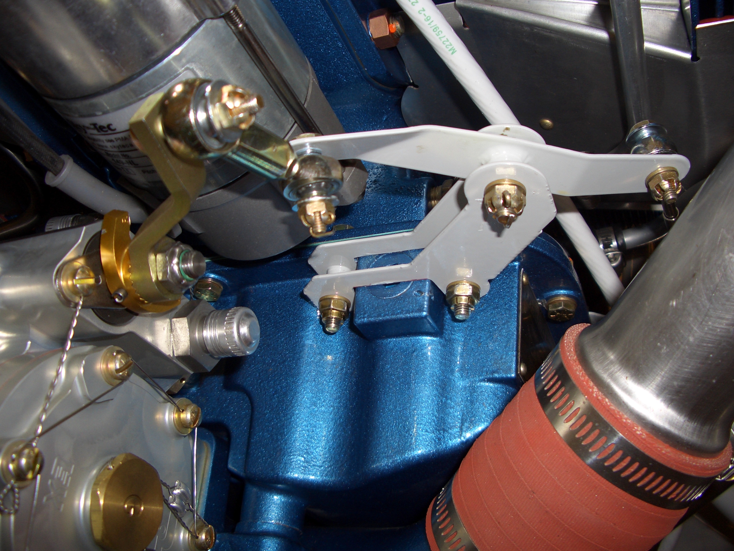
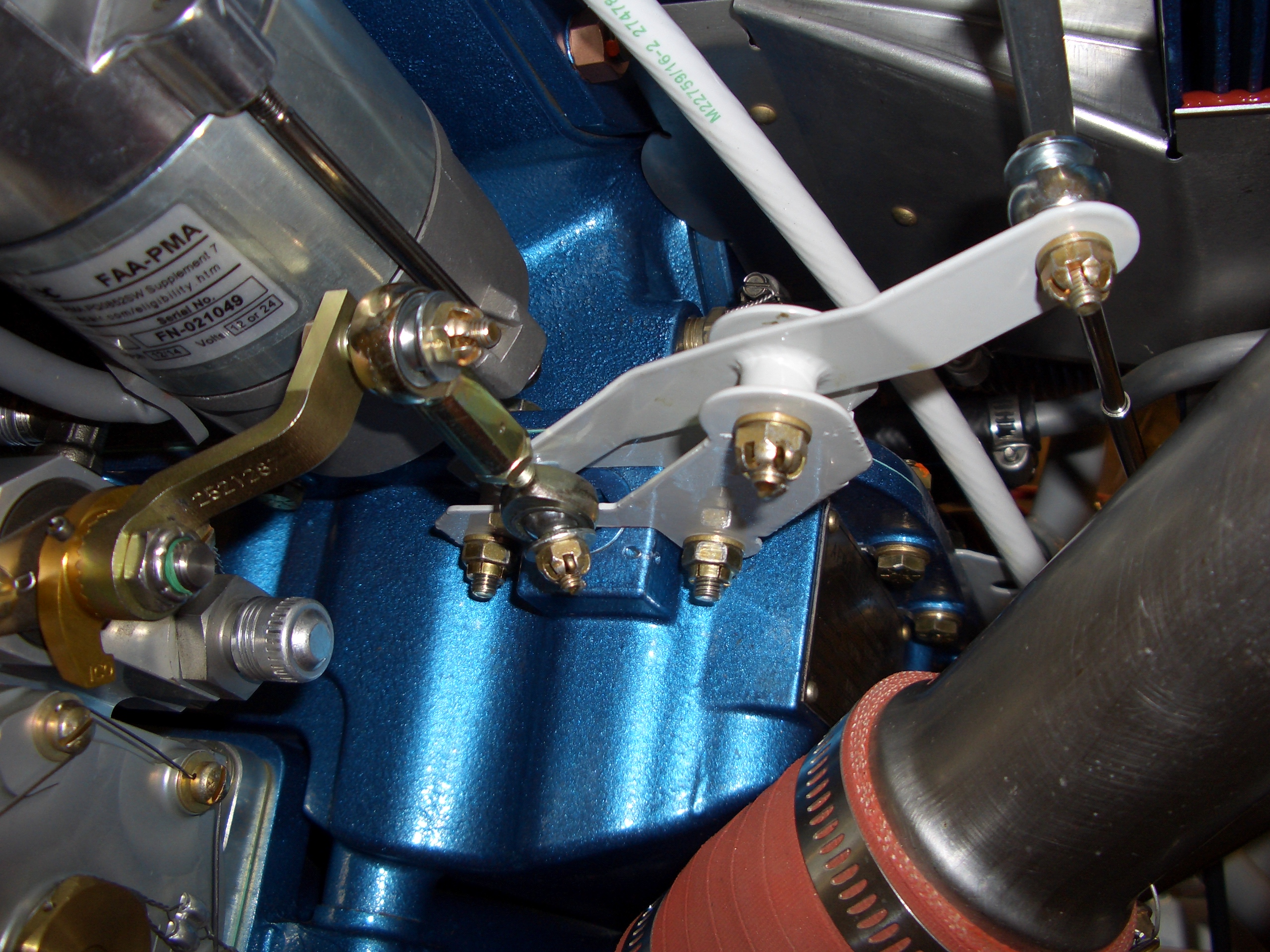
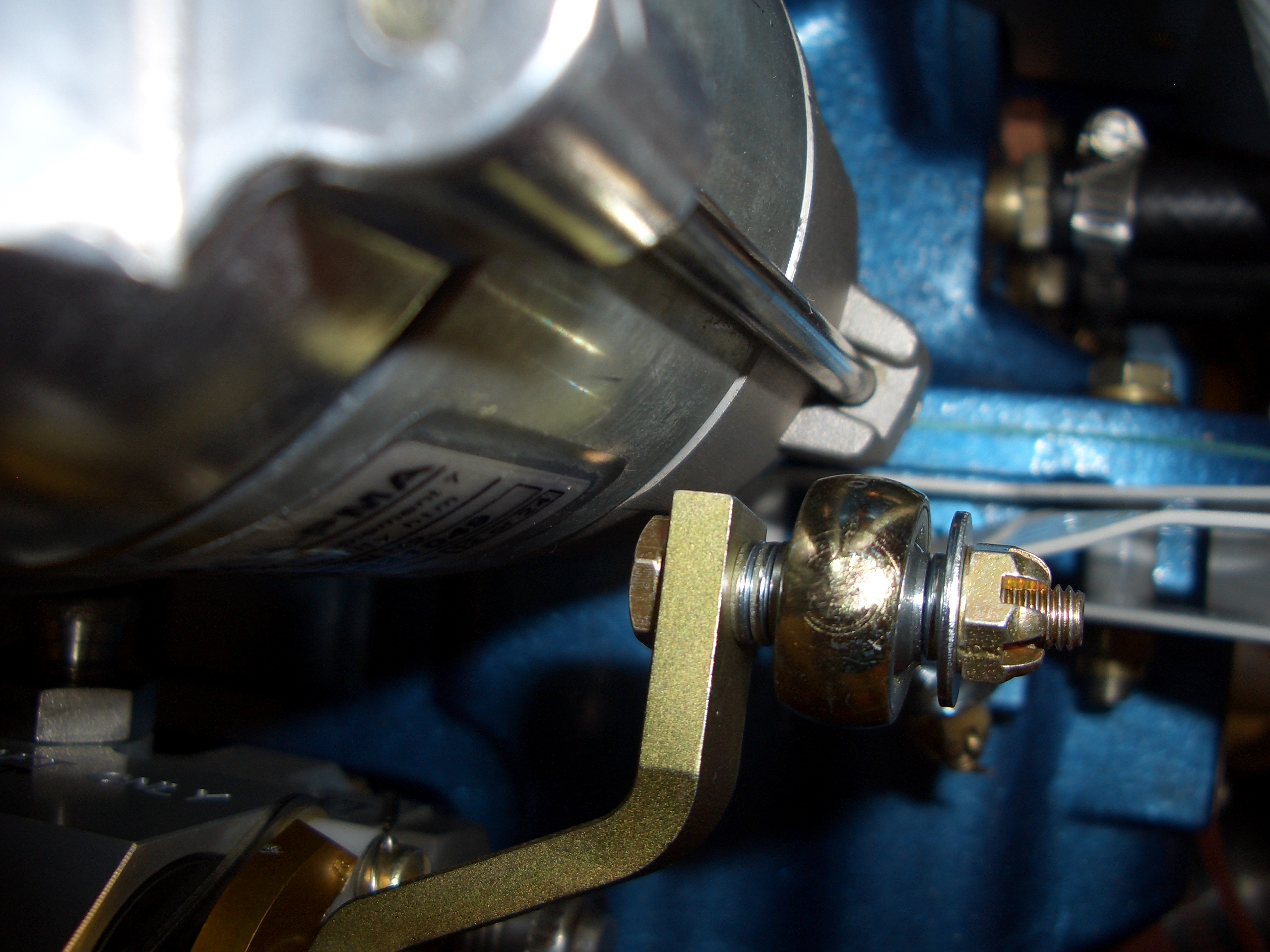
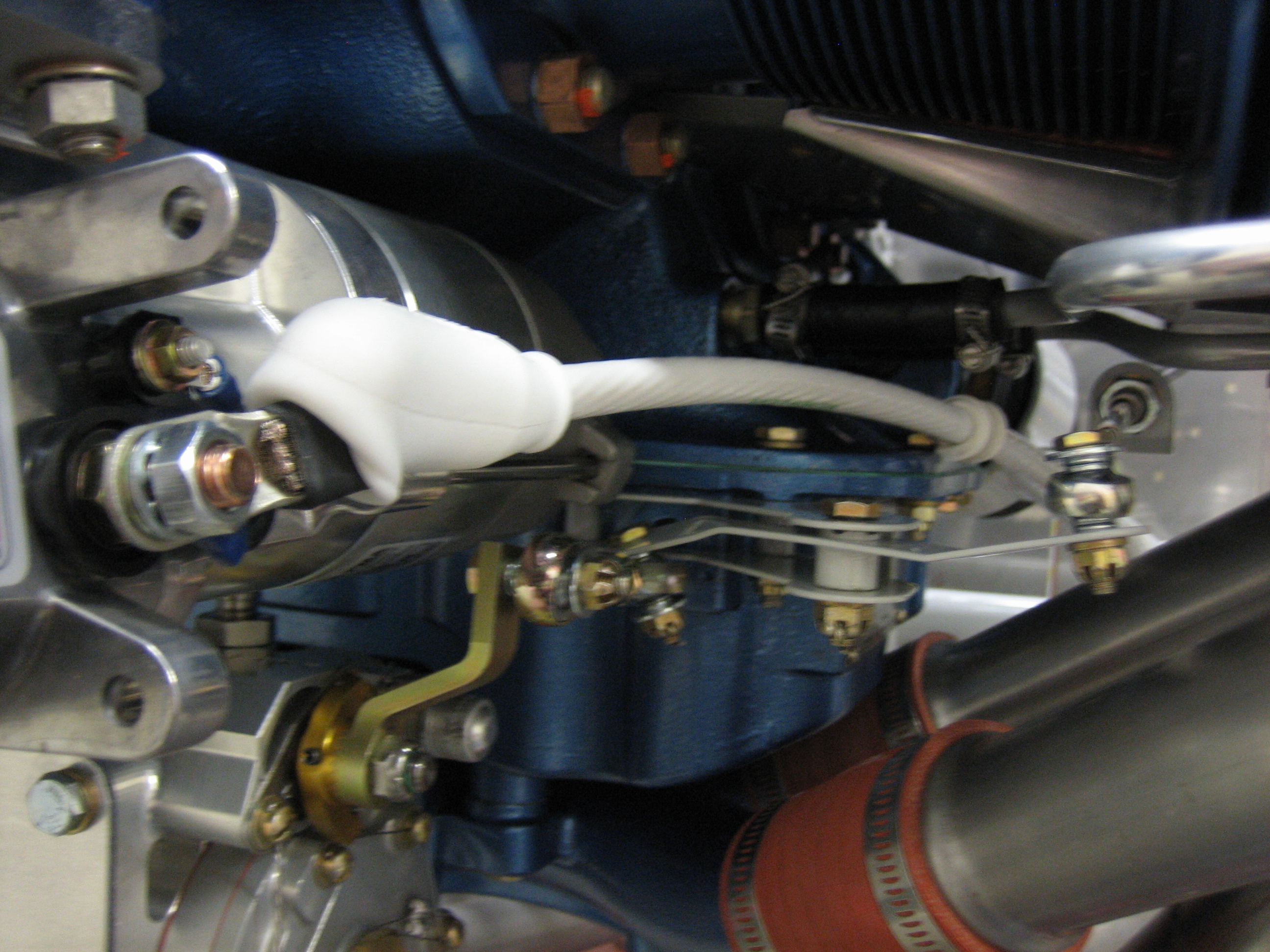
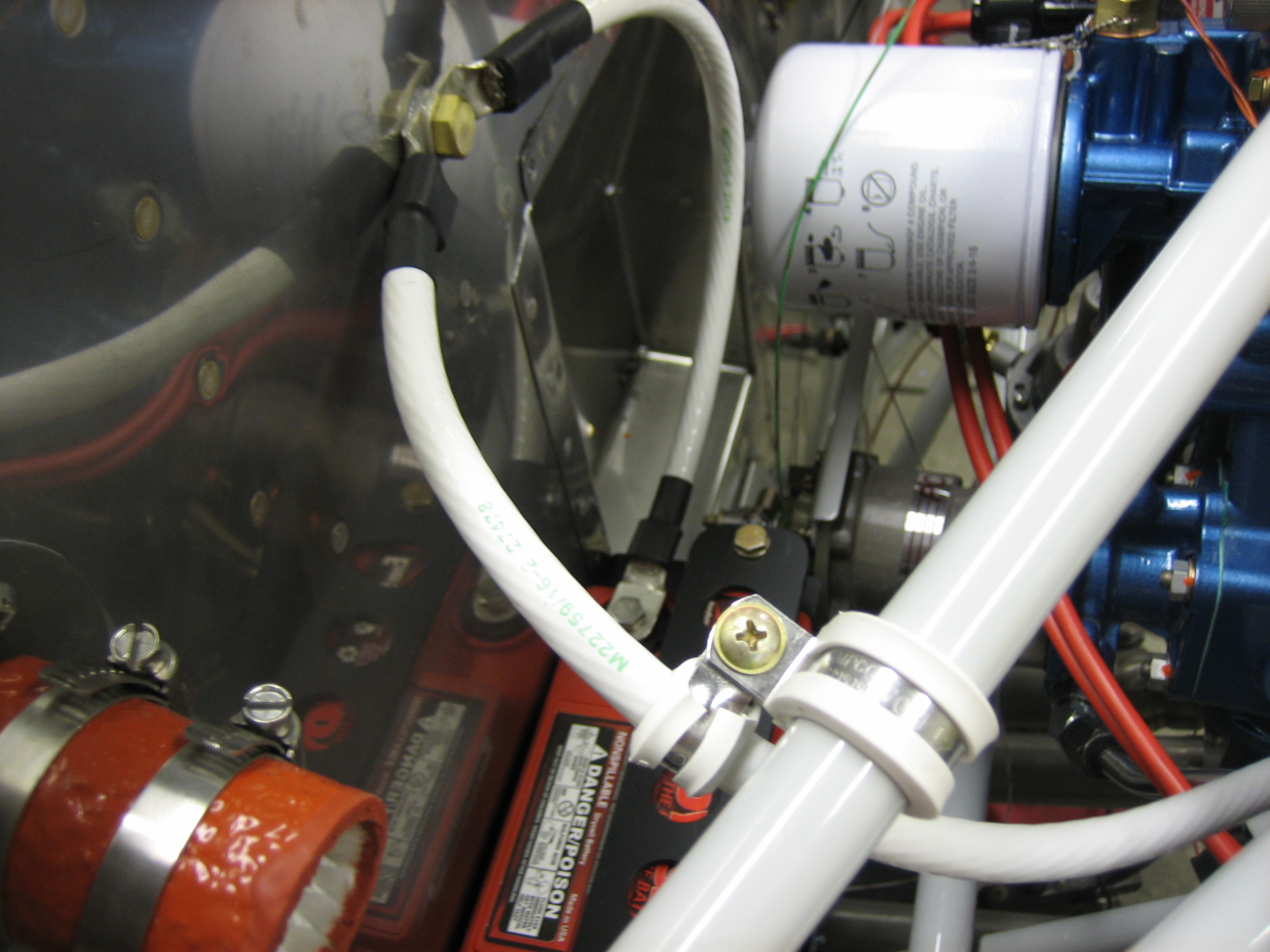
The shorter mixture arm arrived from Precision Airmotive today. I installed it and then spent a little time adjusting the various linkages to get proper movement. Here is the linkage in the idle cutoff position.

The shorter mixture arm arrived from Precision Airmotive today. I installed it and then spent a little time adjusting the various linkages to get proper movement. Here is the linkage in the idle cutoff position.
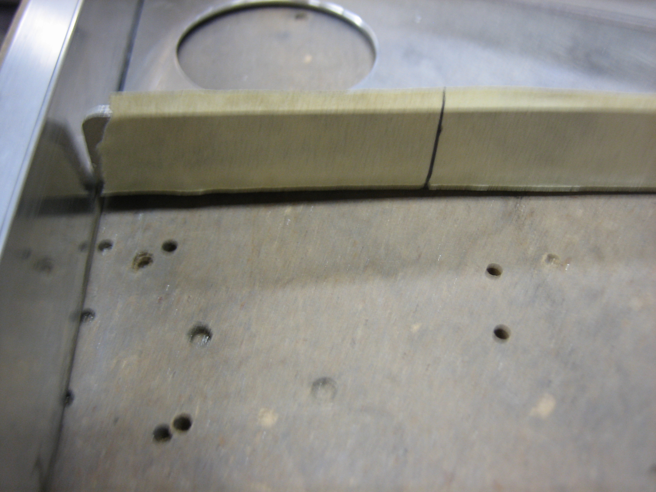
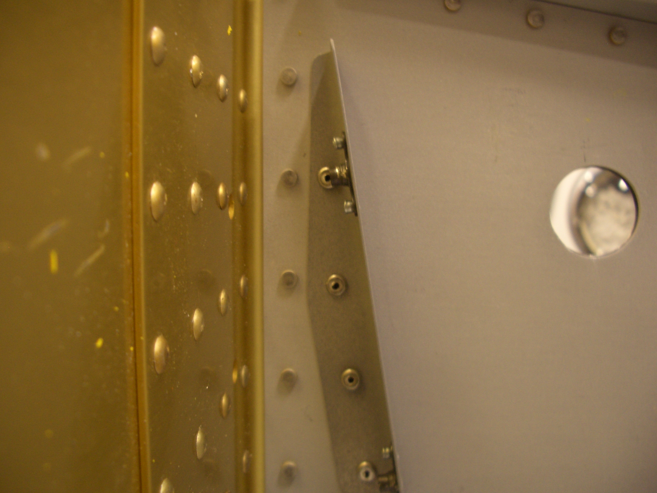
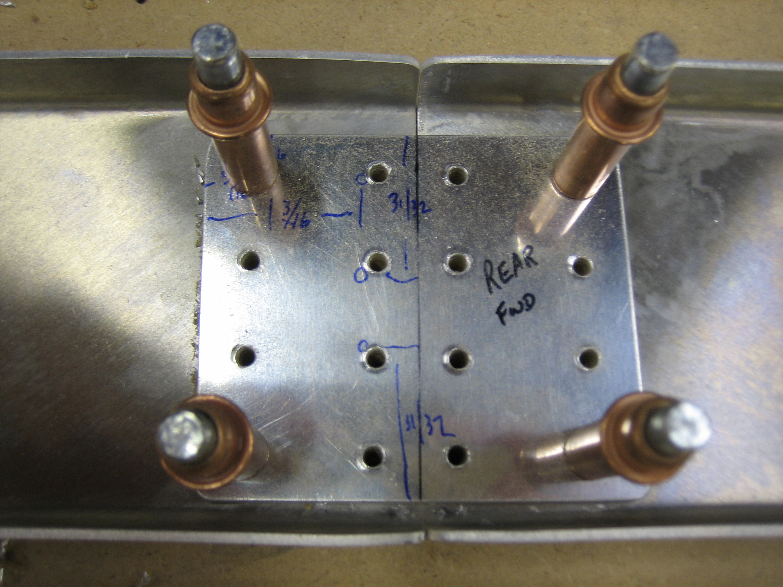
I used a couple of straight edges clamped to the other spar cover attach brackets to define the position of the outer attach angles. I then duct taped the angle in place and match drilled it to the gear webs.
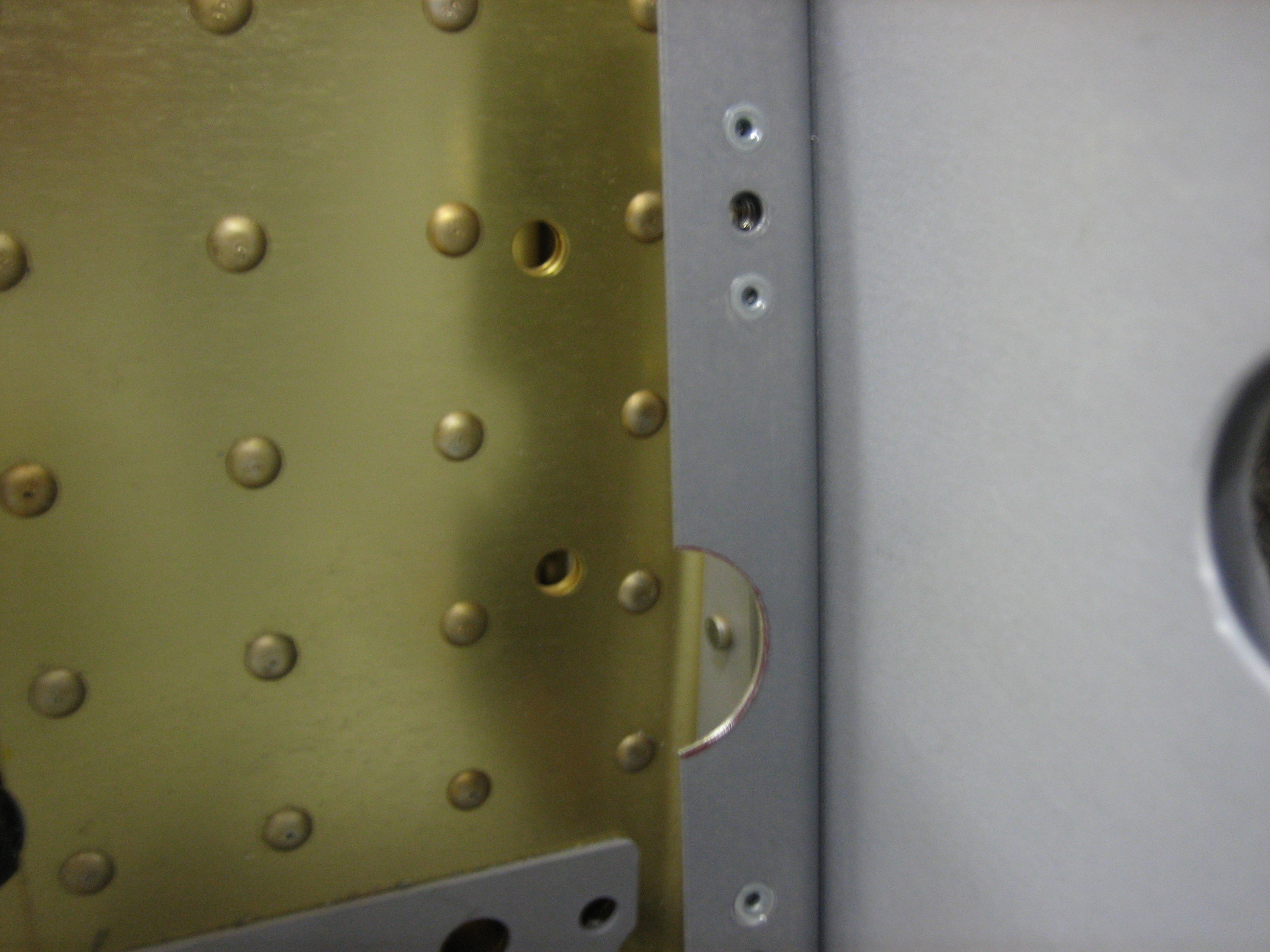
I blind riveted the attach angles to the gear webs using LP4-3 rivets. I had to grind down the tips of the rivets and pull them in small steps (pounding the rivets further in each time).
I also installed the nutplates using MK-319-BS rivets since there wasn’t enough room to get a normal rivet squeezer in here after riveting these to the gear webs (and the nutplates couldn’t be installed first since they would have interfered with squeezing the LP4-3 rivets). I just realized that I forgot to cut the notch in these for the fuel line grommet. I’ll have to do that in place.
Happy Father’s Day everybody!
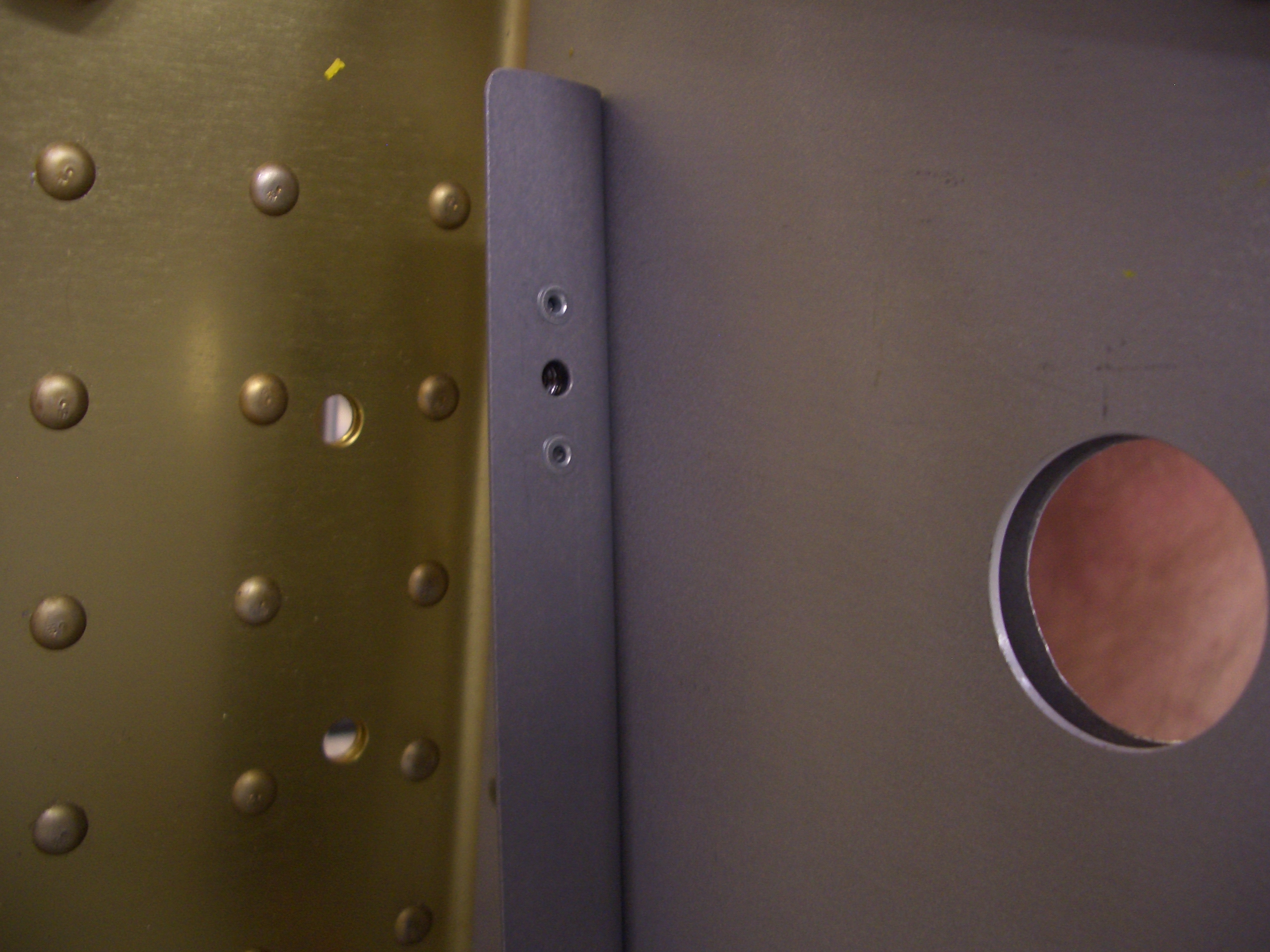
I spent most of the day with family and some friends, but had a little chance to get out into the garage late tonight. First up, I marked and cutout the notches in the outboard forward spar cover attach angles.
Next, I decided to try and bend the fuel lines that come in from the sides of the fuselage and connect to the fuel selector. I knew I shouldn’t have started something like this at 11:30 at night. I got the first piece mostly bent, then realized that I put one of the lines on the wrong mark on the bender and left one leg too long. Attempting to fix it only fucked up the tube enough that I couldn’t get a sleeve to slide over it anymore. I then took the only remaining piece of tubing I had and tried again. After carefully measuring the bends, I proceeded to put one of the lines on the wrong god dammed mark on the bender again and left a different leg too long. Holy fucking christ! I was pretty pissed off by now. I’m out of tubing and it’s expensive as shit to ship these 6′ long pieces from Aircraft Spruce. I don’t want to order just one piece either, because what’s the chance that I’ll bend the next two perfectly. So this was probably a $50 fuck up tonight just because I was not thinking clearly. I’m going to bed…
I called Bonaco this morning and put in an order for a few hoses. I ordered a short hose that will run from the fuel bulkhead on the firewall to the inlet of the engine driven pump. I also ordered the hose that run from the outlet of the engine driven pump to the fuel servo. This hose needed 45º fittings on each end with 270º clocking. We’ll see soon if I measured correctly. I also picked up the hoses that run from the brake fluid reservoir down to the master cylinders. Since all of my other brake components are black, I had Brett do these in black as well. Finally, I ordered the brake lines that go from the bulkhead fittings on the firewall down to the wheel cylinders. Van’s plans call for rigid lines from the bulkheads down to the wheel cylinders with generous service loops inside the wheel pants to allow for flex and vibration. This is a notorious source of cracking though due to flex in the aluminum line. Since aluminum doesn’t have a fatigue limit, even minor flexing will eventually result in failure. Even the MIL-PRF-83282D brake fluid (which is a huge improvement over the old MIL-H-5606 fluid) is flammable, so a brake line failure can really ruin your day. Some people run rigid tubing down the leg and transition to flex line near the wheel cylinder, but the whole gear leg flexes when on the ground, so this really doesn’t eliminate the line flex.
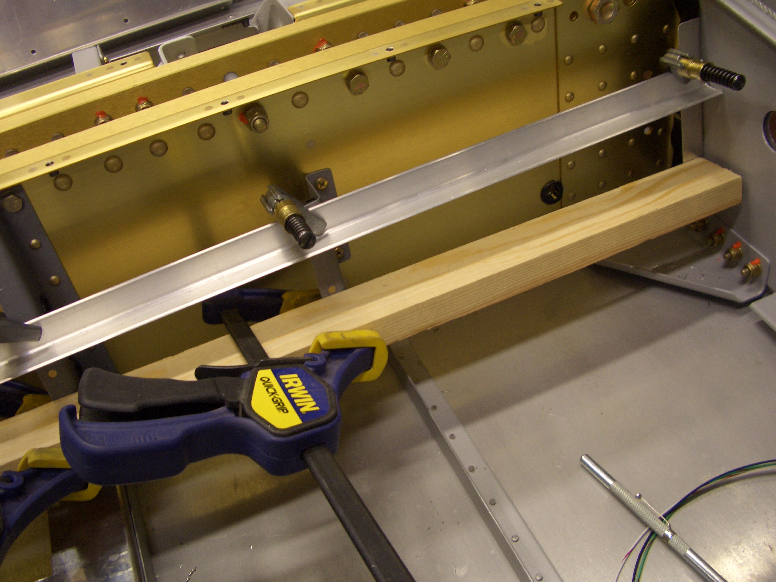
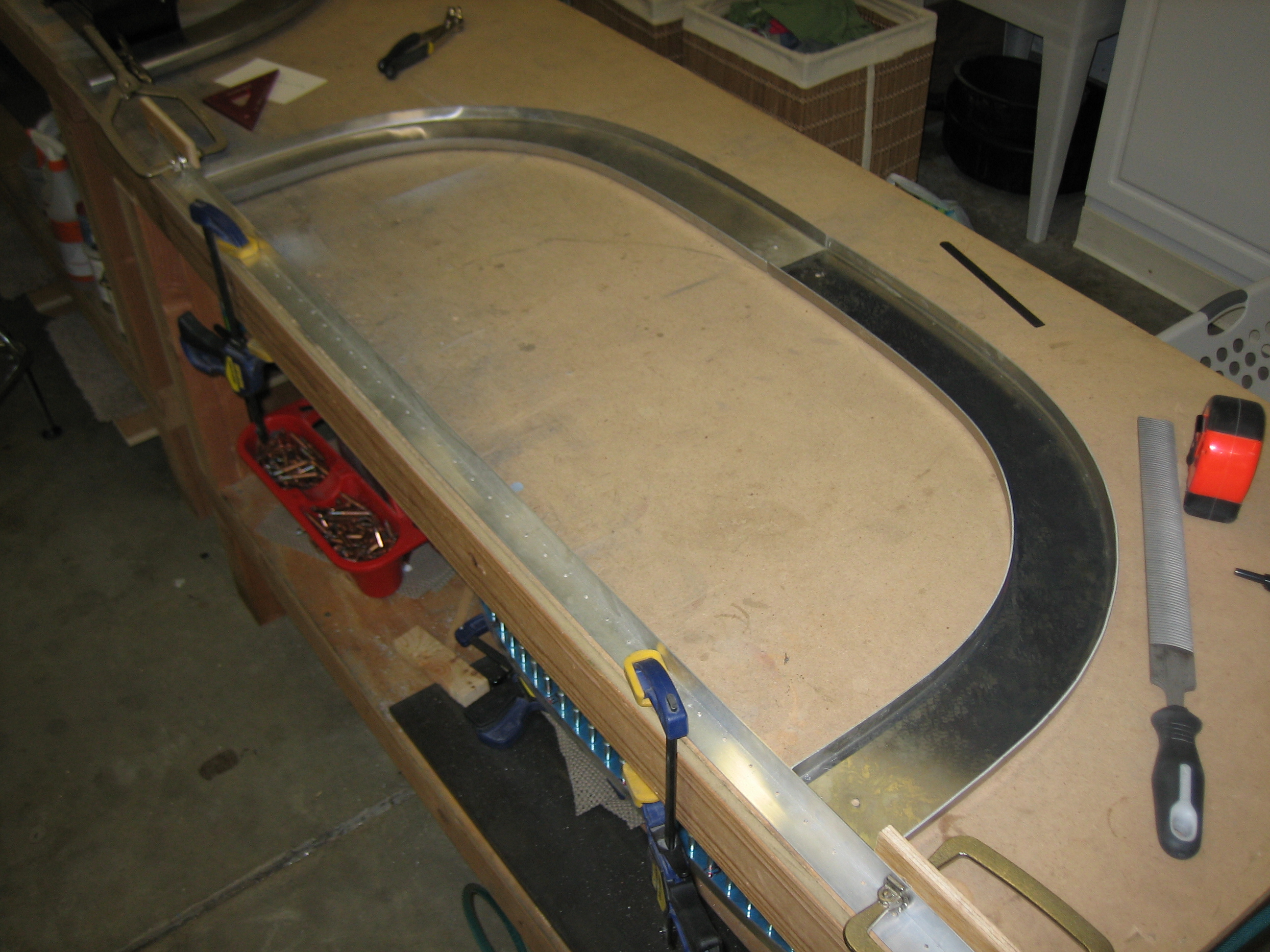
Since I’m waiting on an order from Aircraft Spruce for new 5052 brake lines, I decided to get started on the cabin frame. I clamped a straight edge to the bench and then clamped wooden blocks to the vertical legs to define the overall width of the frame.
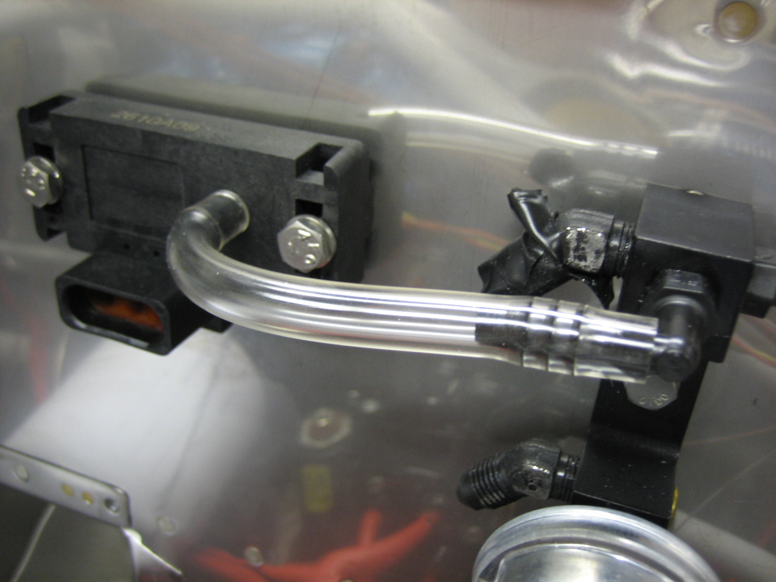
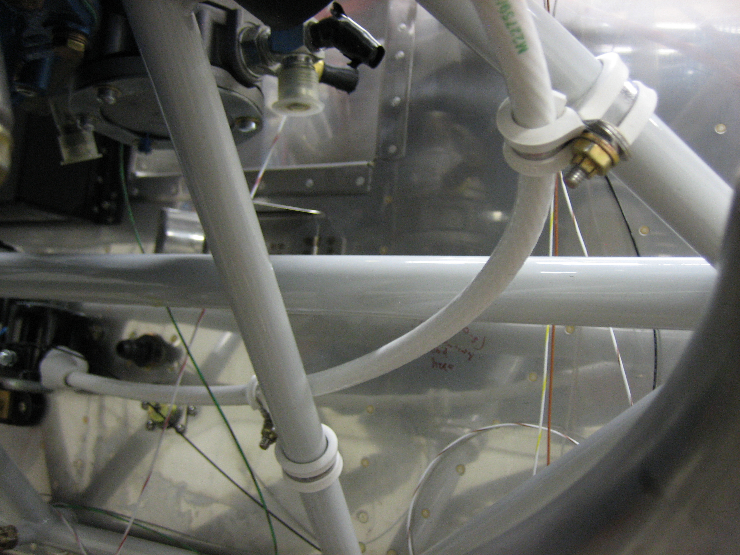
An order from Aircraft Spruce showed up today with some 1/4″ ID tygon tubing. I cut a short piece to connect one outlet of the pressure transducer manifold port to the Dynon manifold pressure sensor.
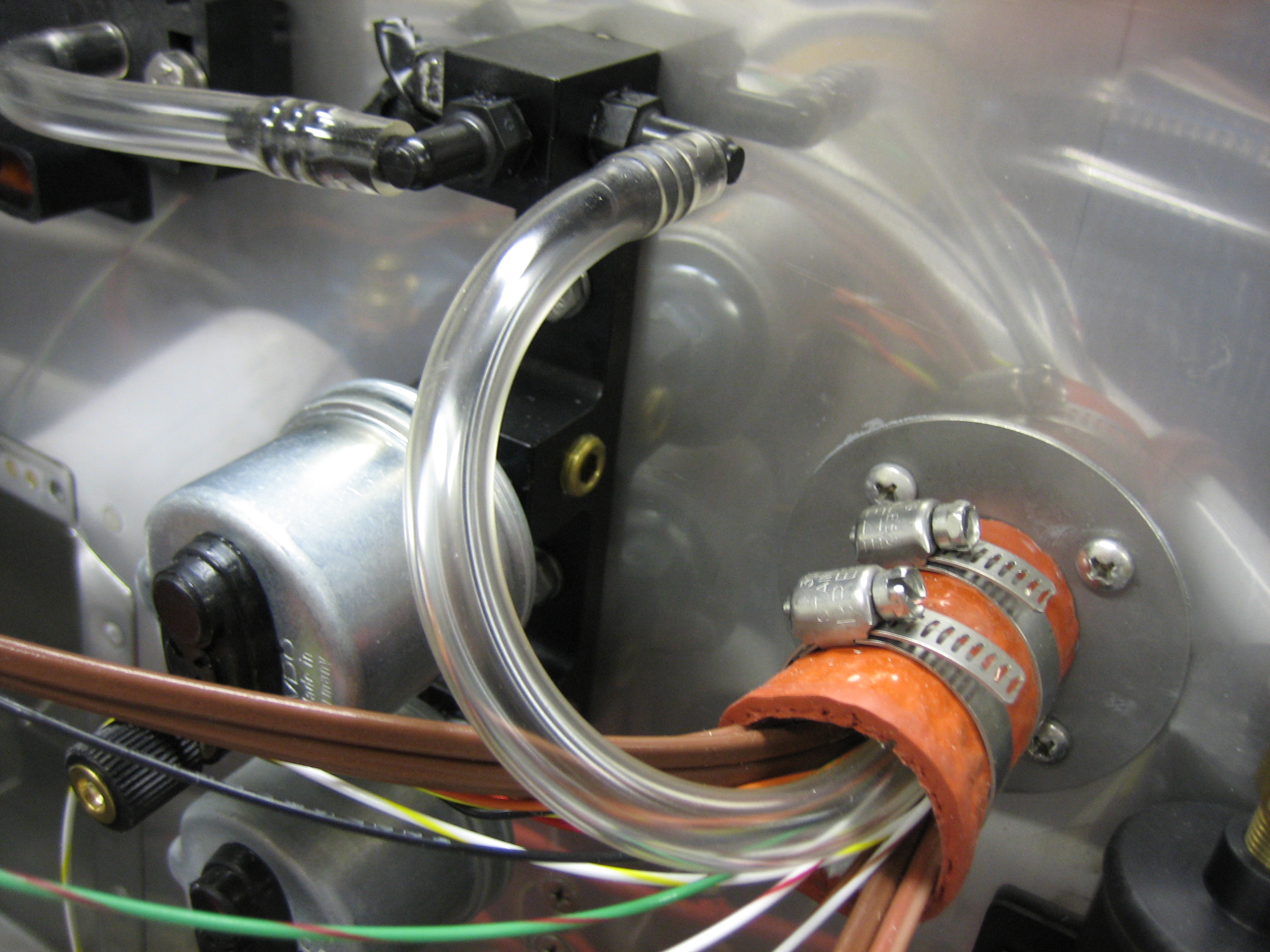
I used the remaining tubing to connect to the other outlet and ran this through the firewall passthrough. Inside the fuselage, I’ll transition from 1/4″ ID tubing to 1/8″ ID tubing for the connection to the Lightspeed electronic ignition.
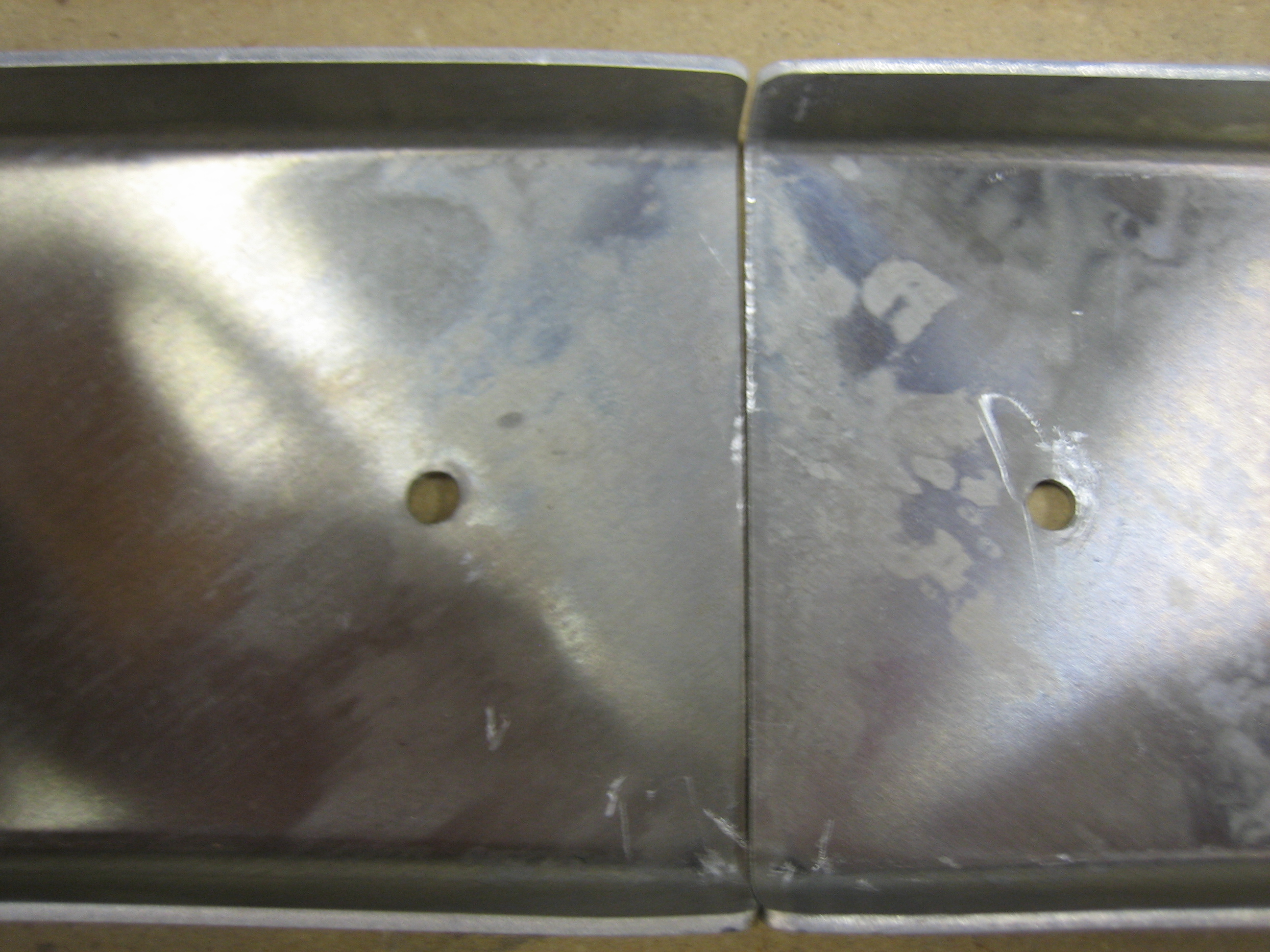
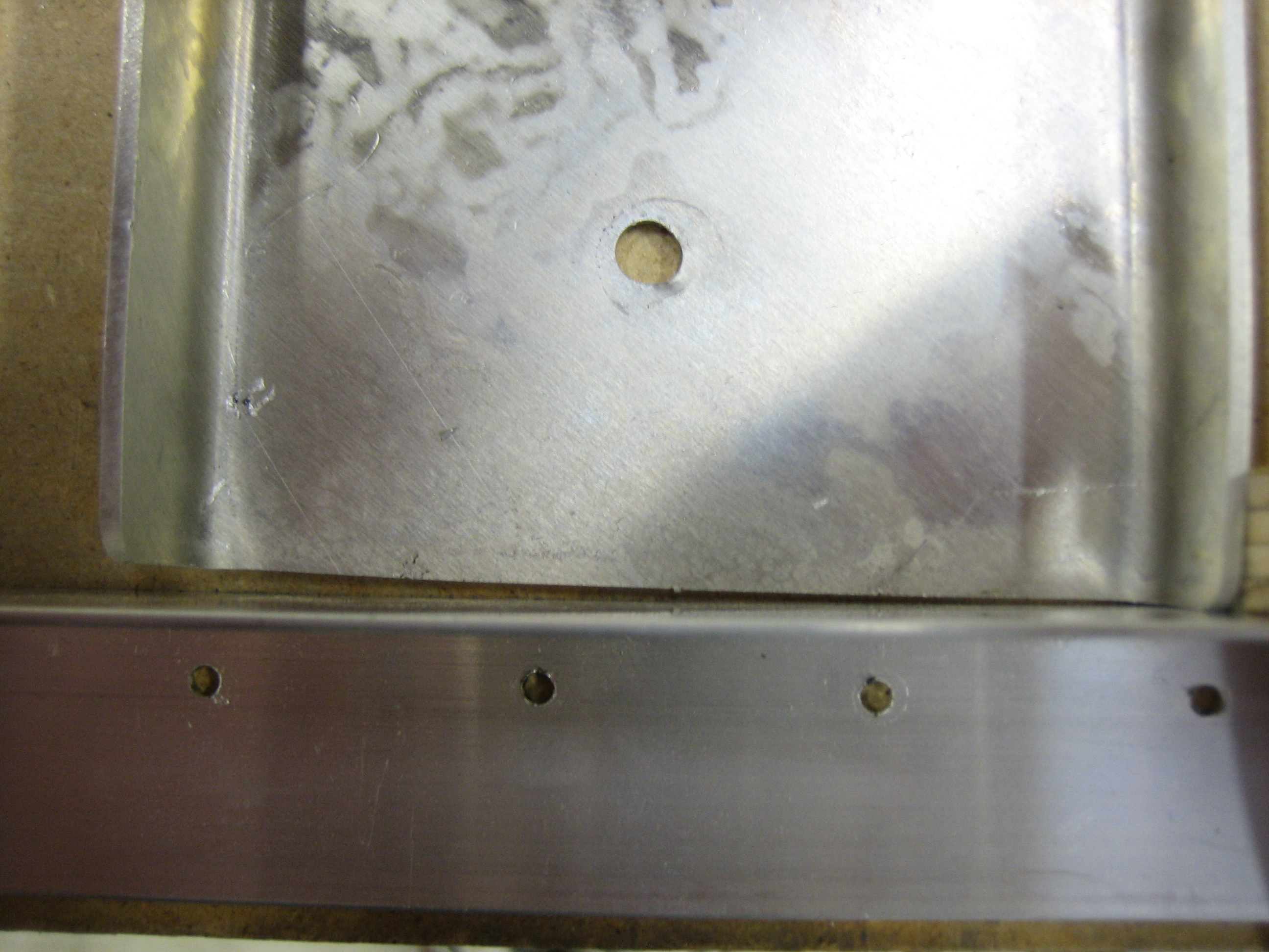
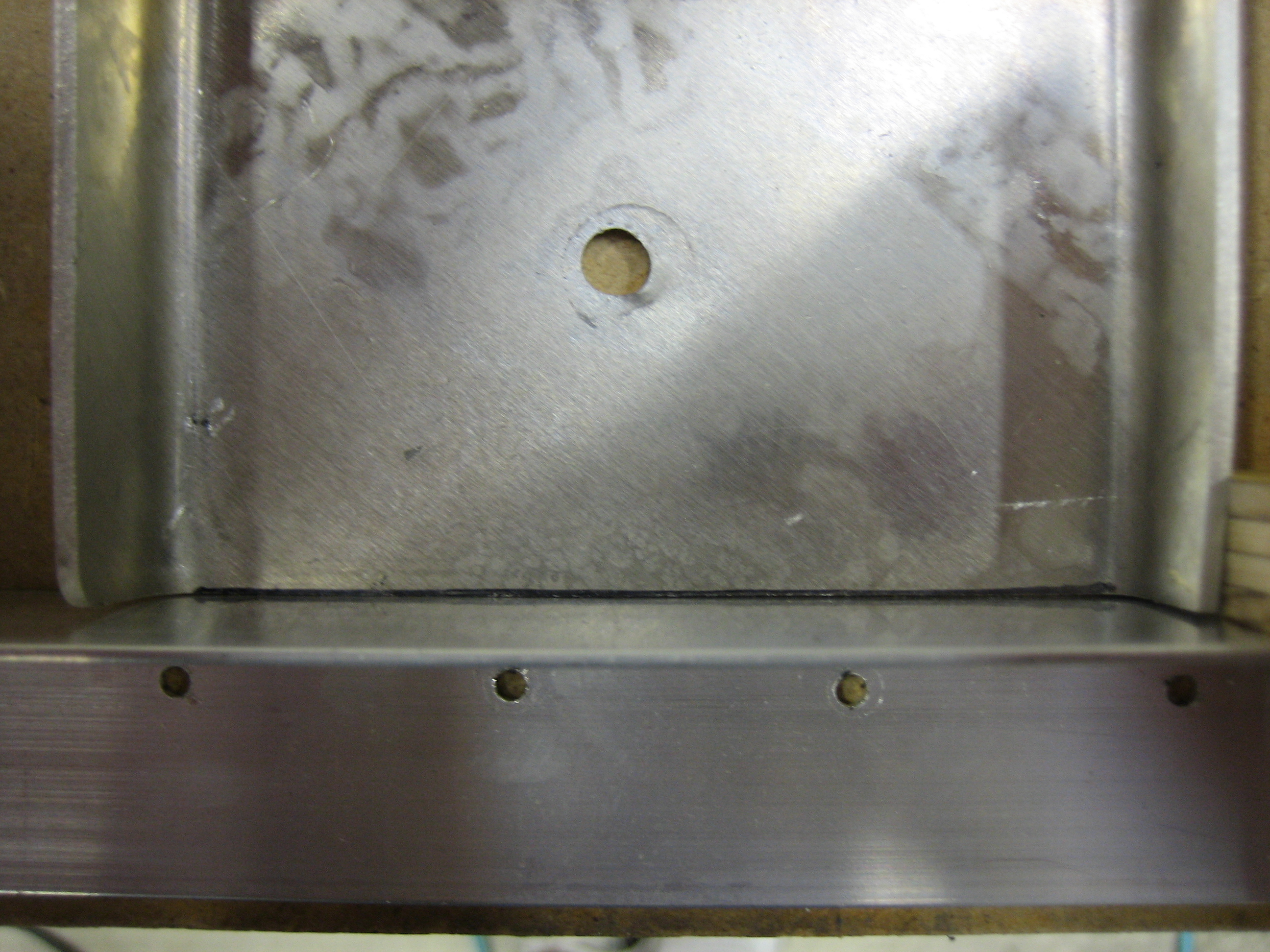
Finally, I fabricated the splice plates for the cabin frame halves. The pieces that Vans provided for this were not square. The two short edges were not perpendicular to the long edges. I laid the holes out square though since the rivets will be seen on the outside of the cabin frame.
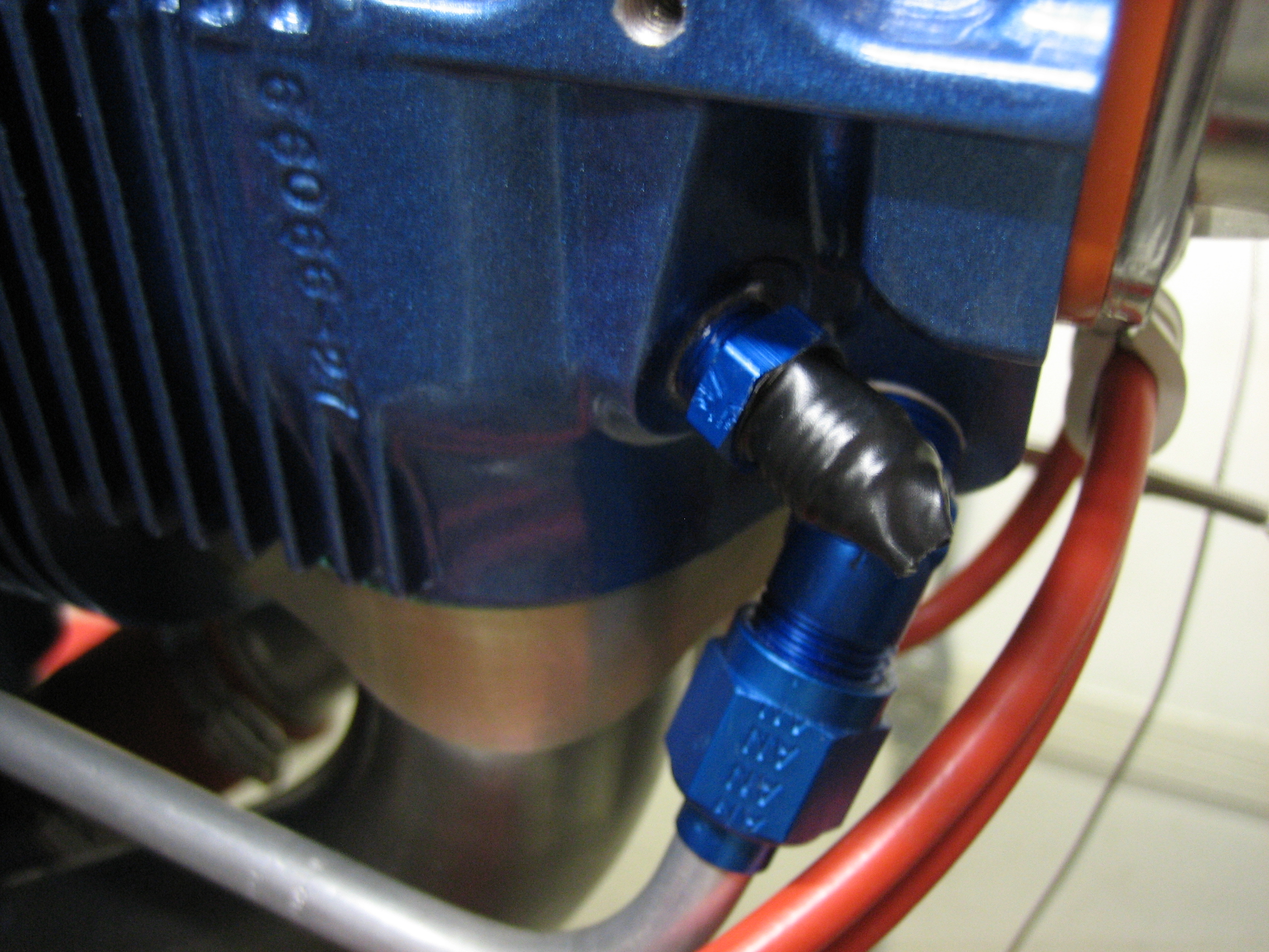
I received another order from Aircraft Spruce today with this AN816-4D fitting that is used to tie the manifold pressure line into the #3 cylinder. The end is taped off with electrical tape to keep moisture out of the cylinder until the manifold pressure line is installed.
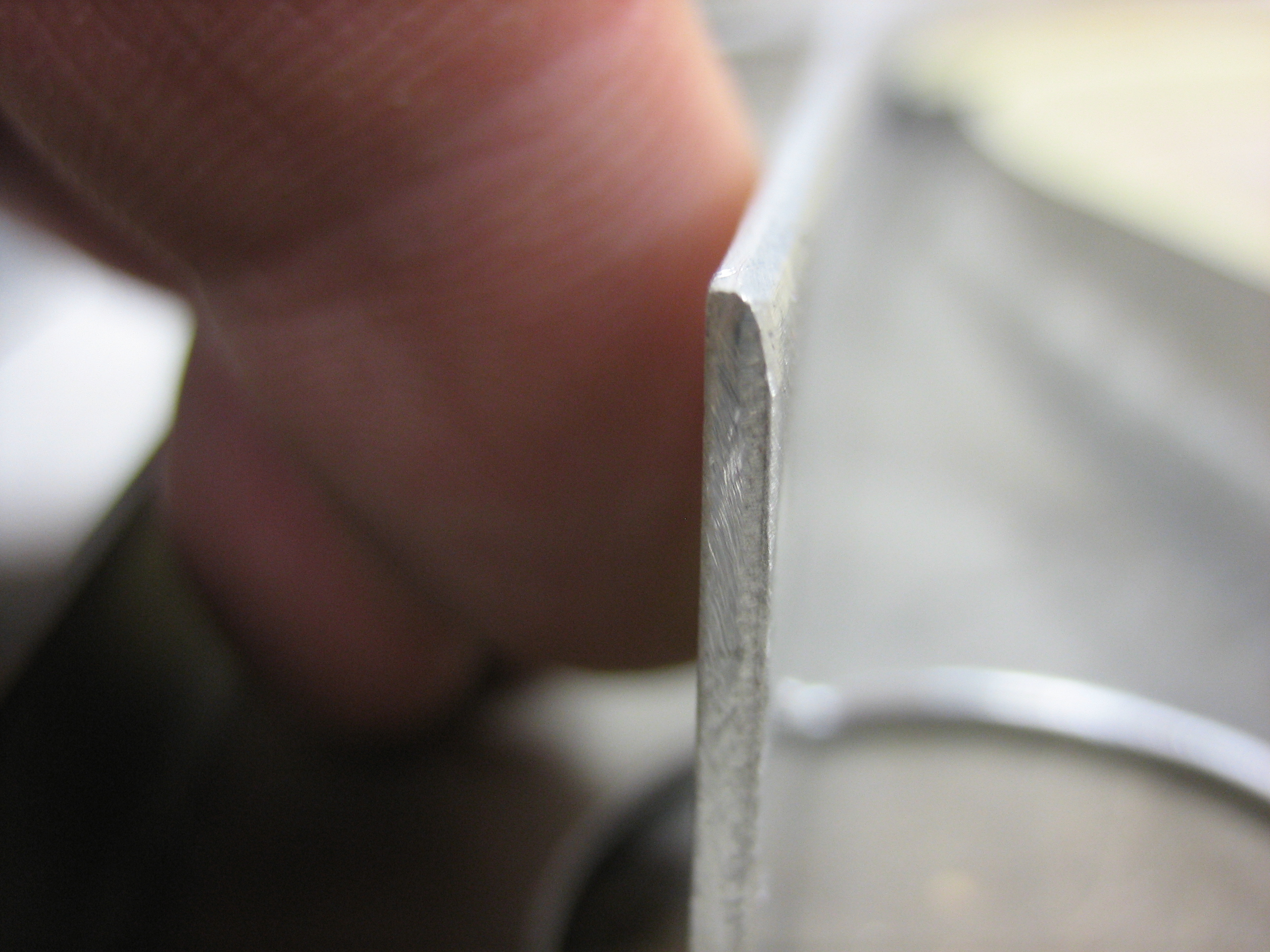
I rounded over the edges of the canopy frame joint strips. These join the front and back halves of the cabin frame. The radius is necessary so that the halves can be pulled tightly together.
I also put a strip of masking tape around the inside edge and marked for the lowest hole. I’ll use a rivet fan to lay out holes along this strip and then use it to drill the holes evenly along the inside edge of the canopy frame.