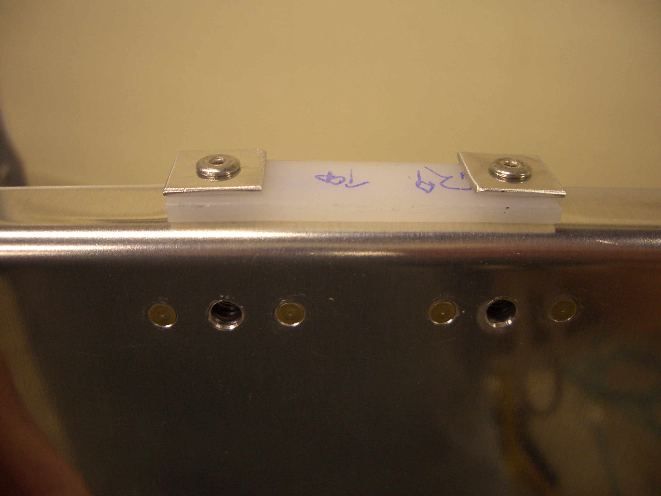
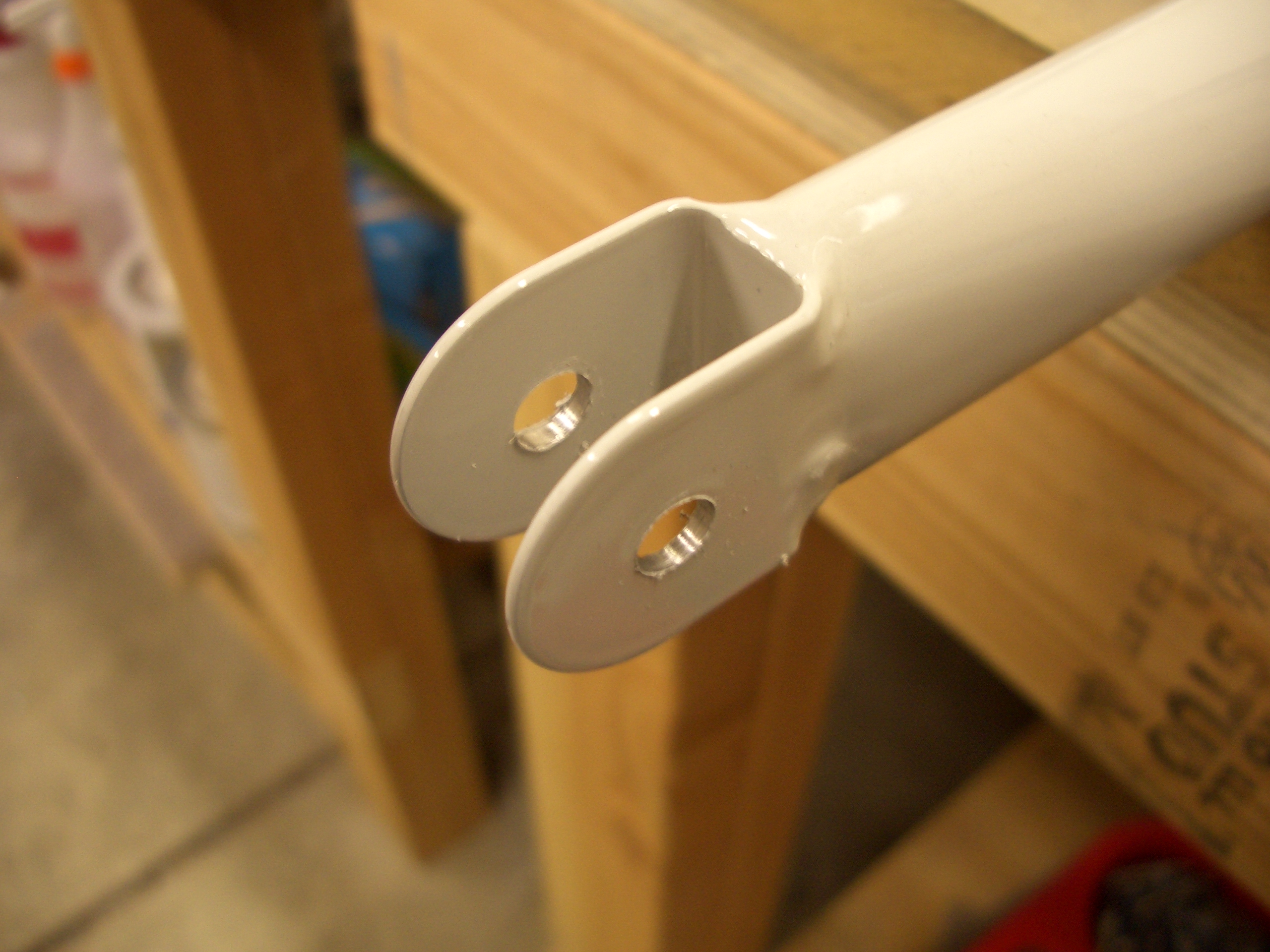
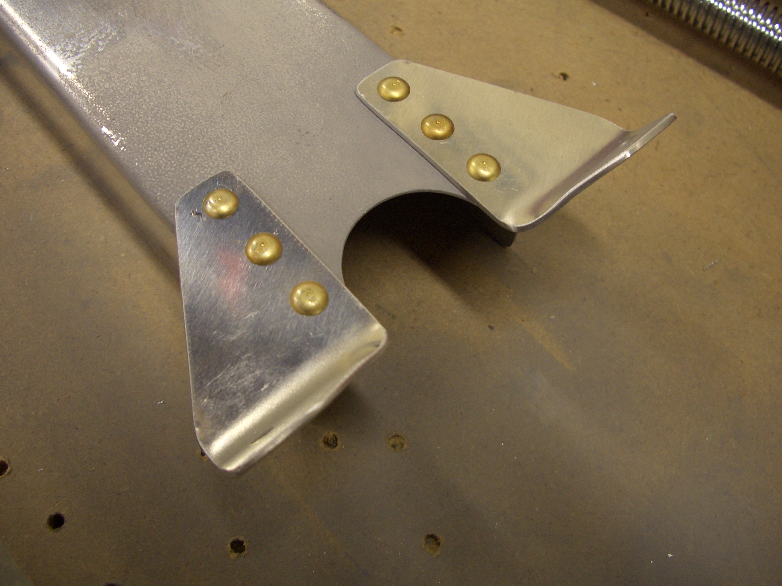
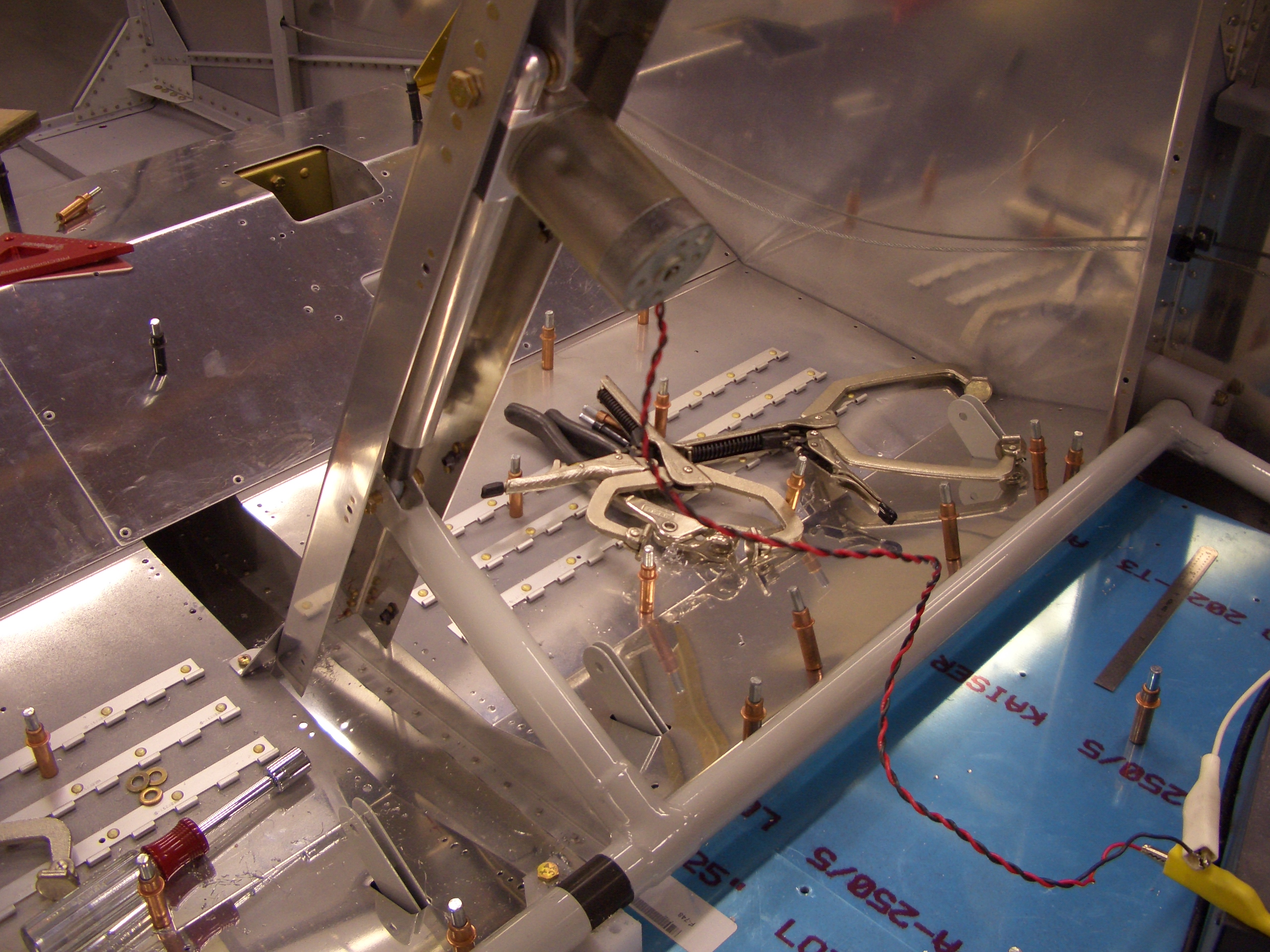
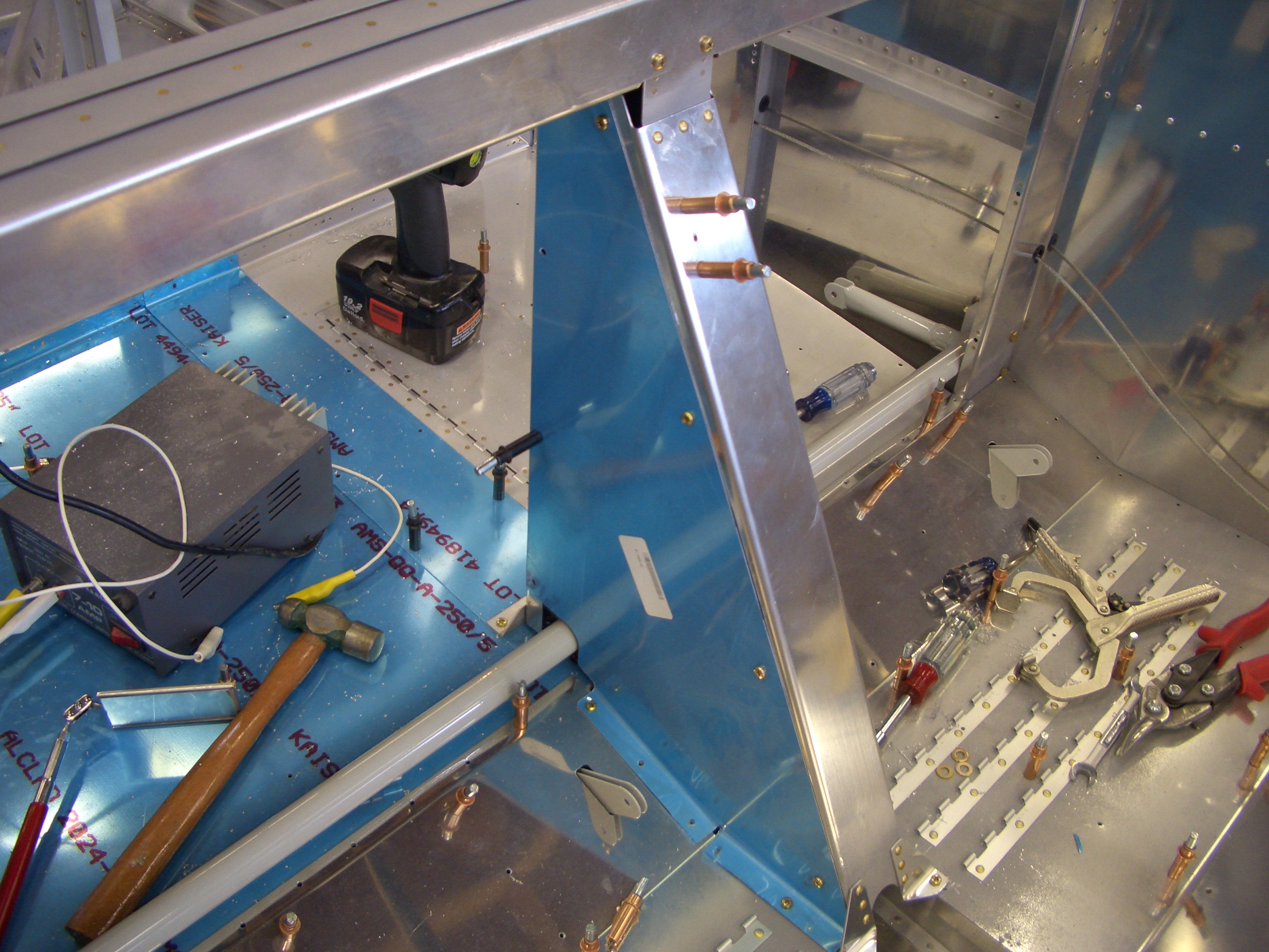
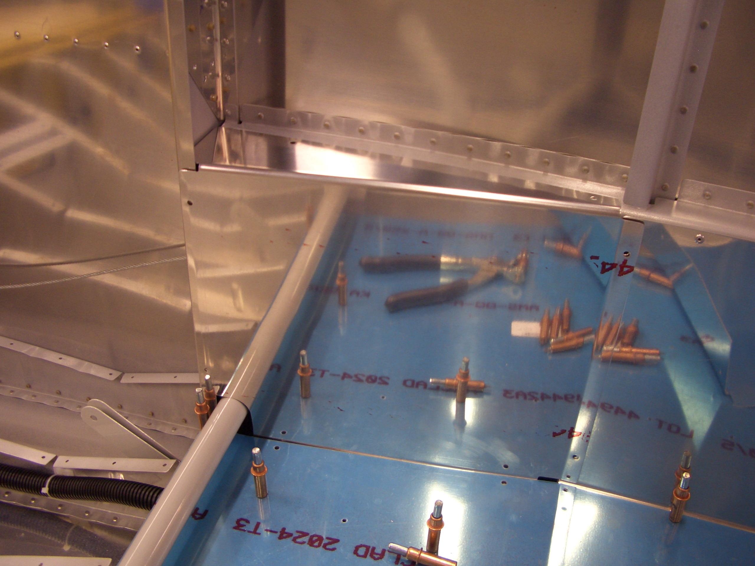
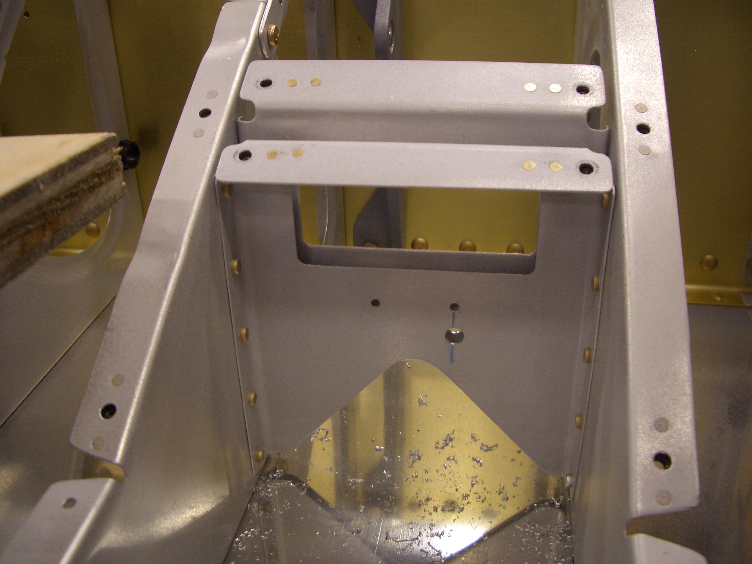
I installed the baffle in the vertical portion of the front cover (just below where the air vents are in the cover). I didn’t get a picture of it, but it needs to be match drilled and riveted along with a handful of nutplates.

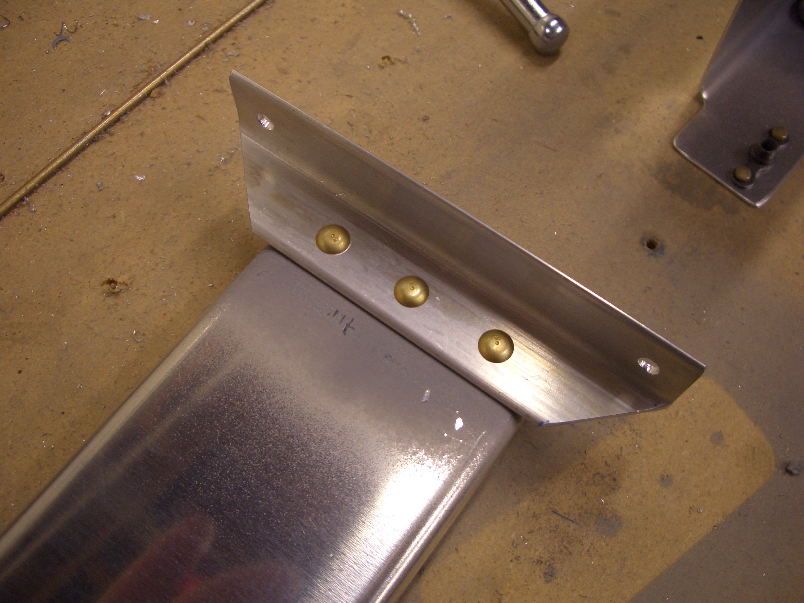
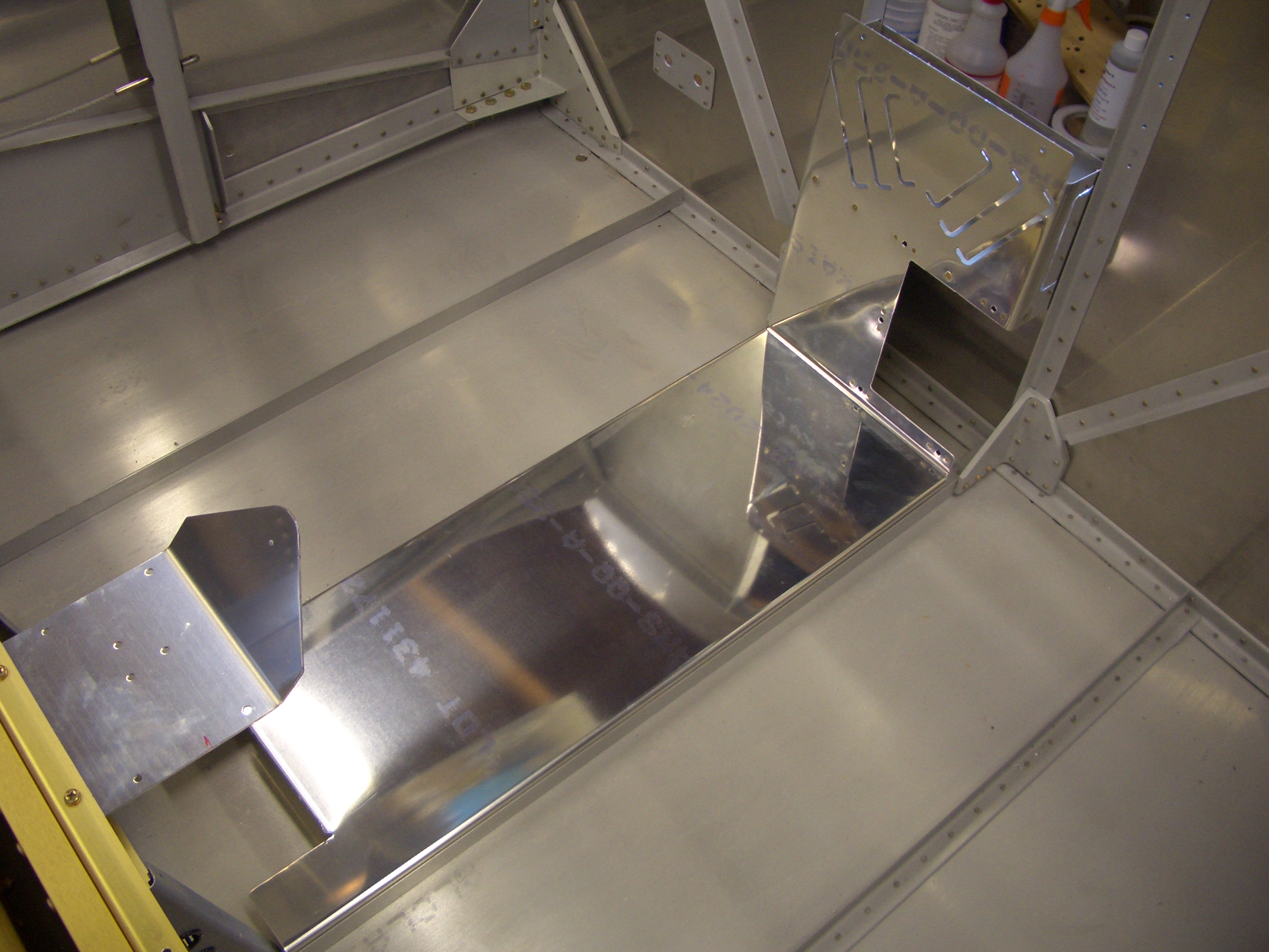
I also installed the fuel selector mounting bracket and cover that ties the bracket and lower cover together.

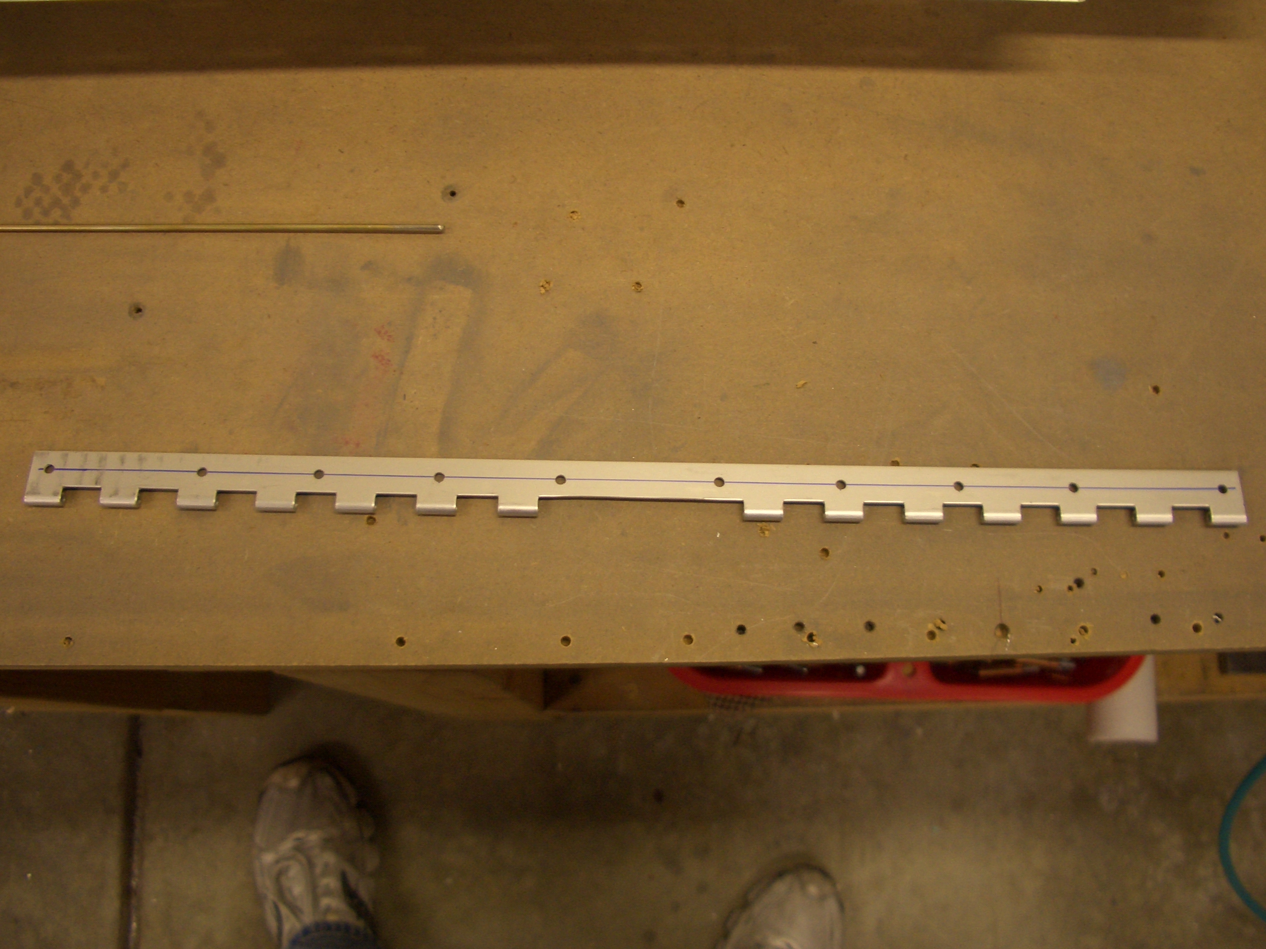
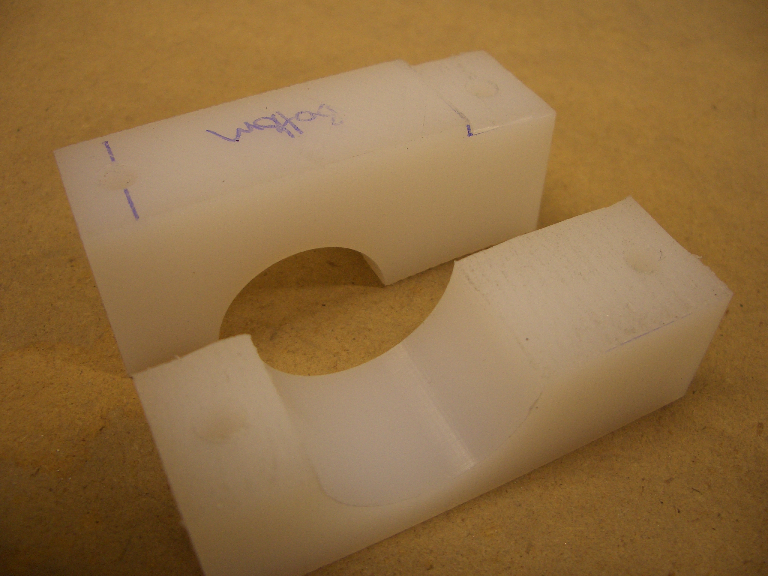
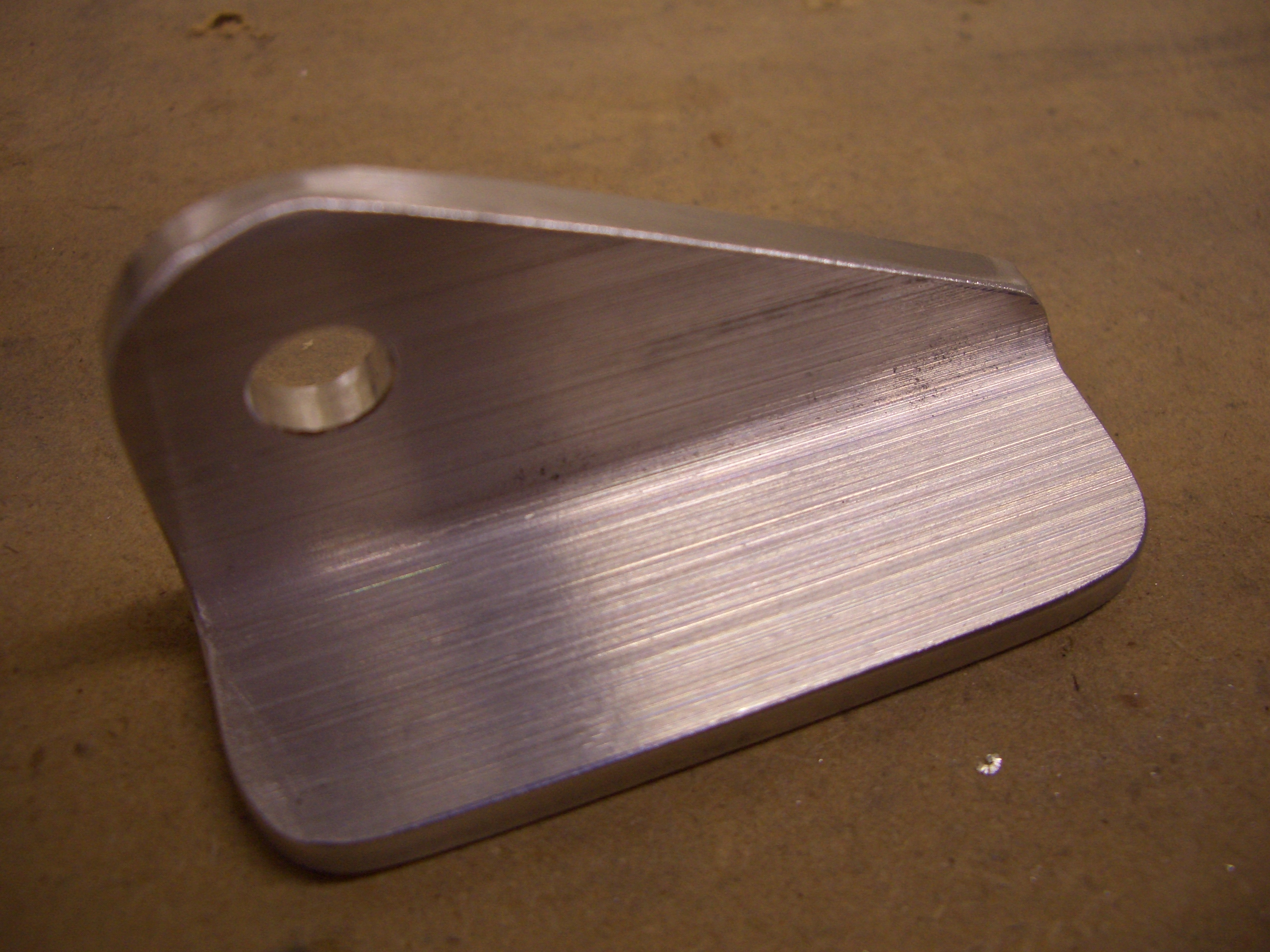
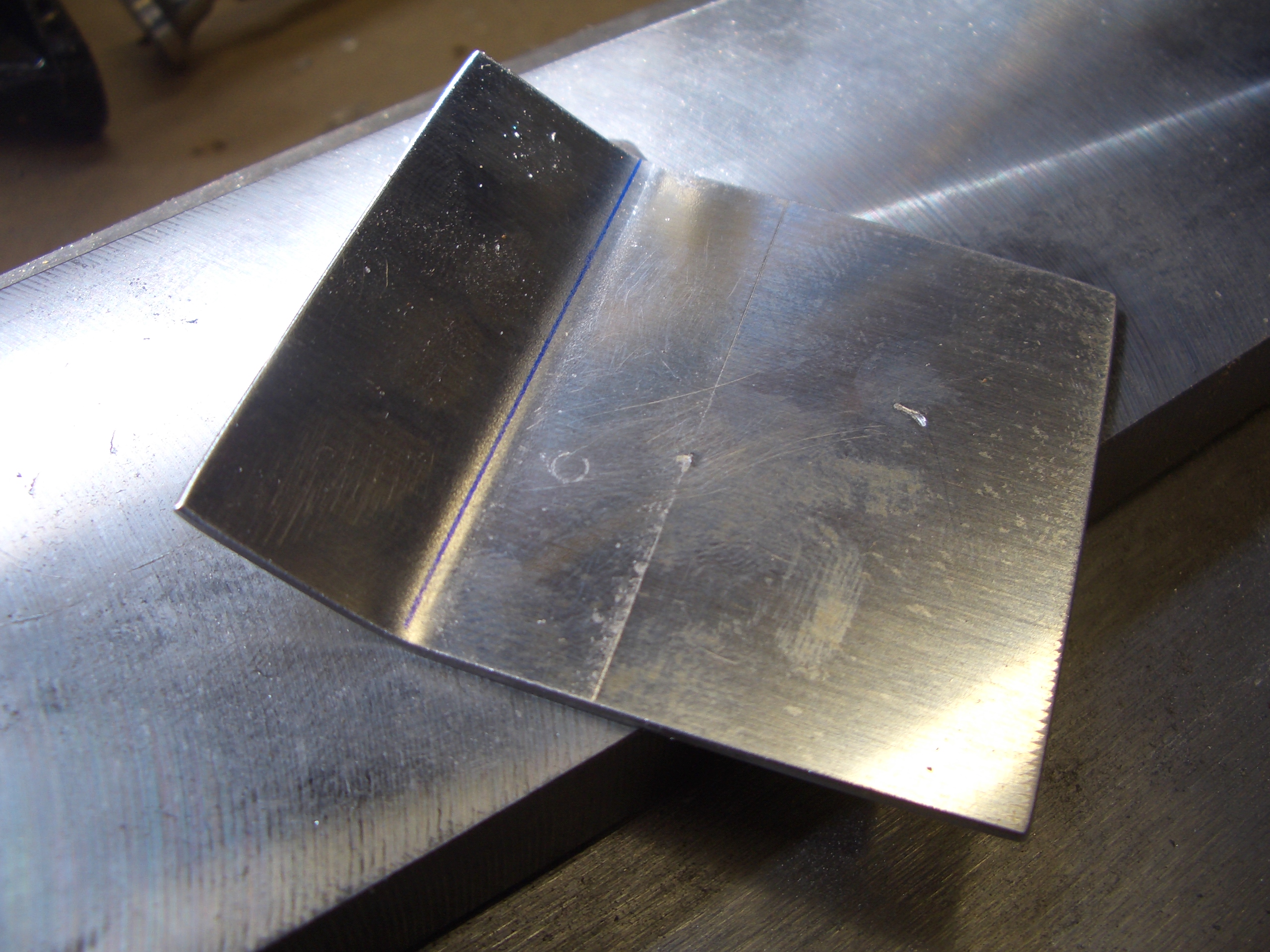
I was planning on cutting off the angled triangular portion since I’m not using the manual elevator trim. I noticed however that that would leave a large gap between the fuel selector bracket and the vertical cover. Instead, I flipped the bracket over and will cut off the triangular flange slightly forward of the bend to cover the gap.
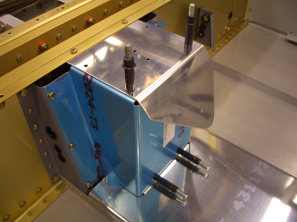
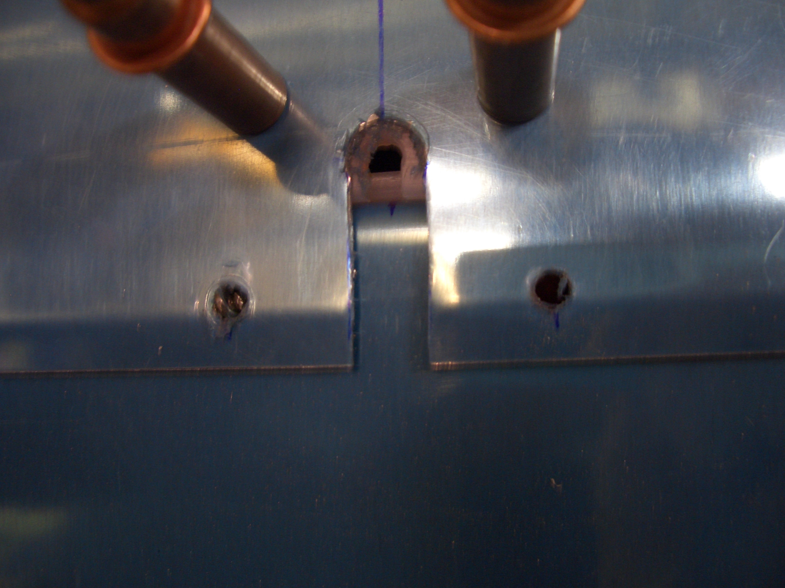
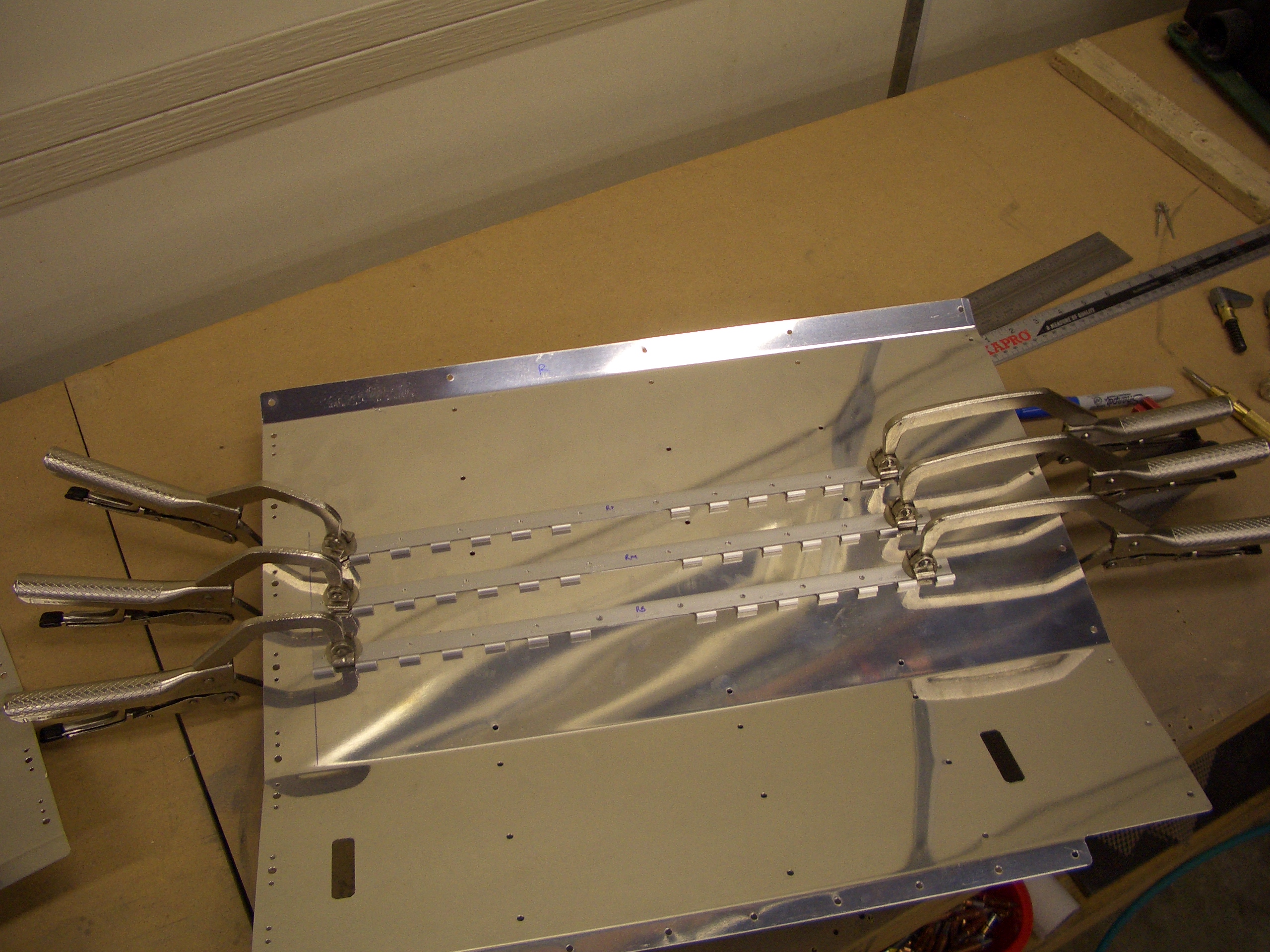
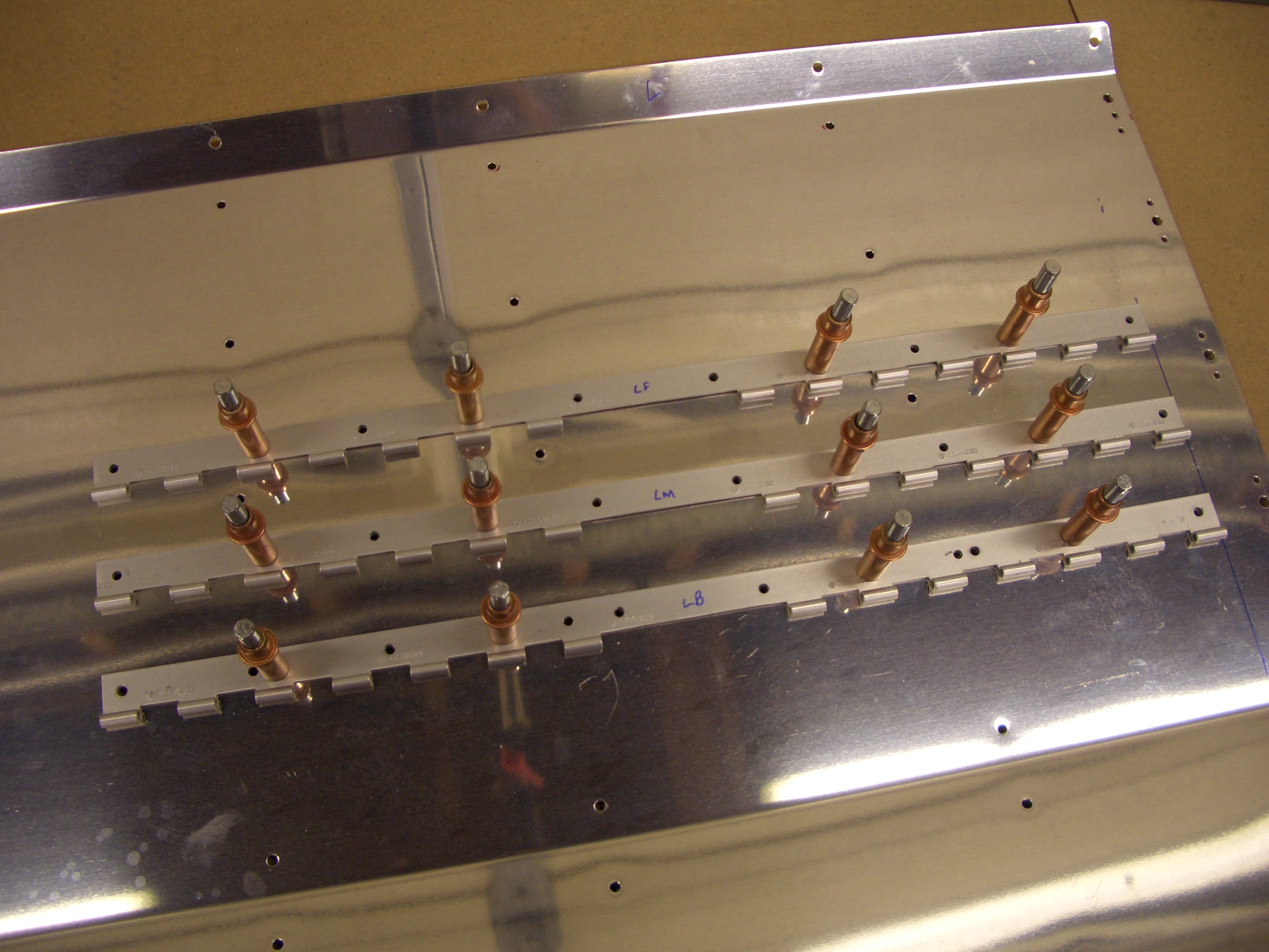
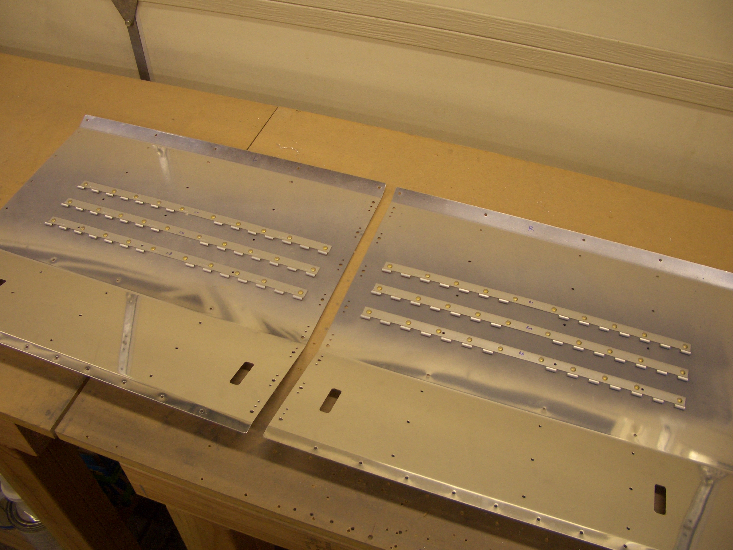
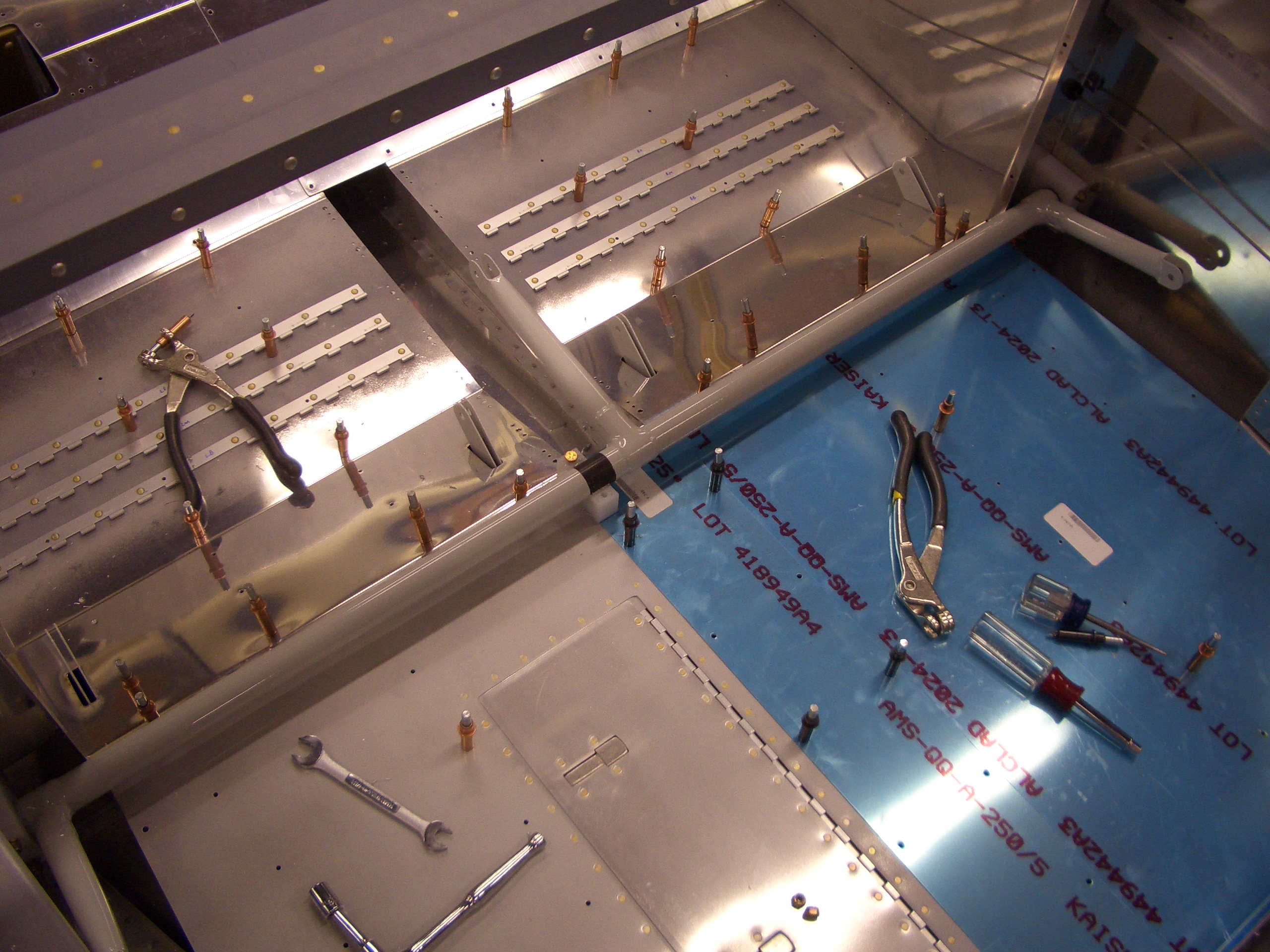
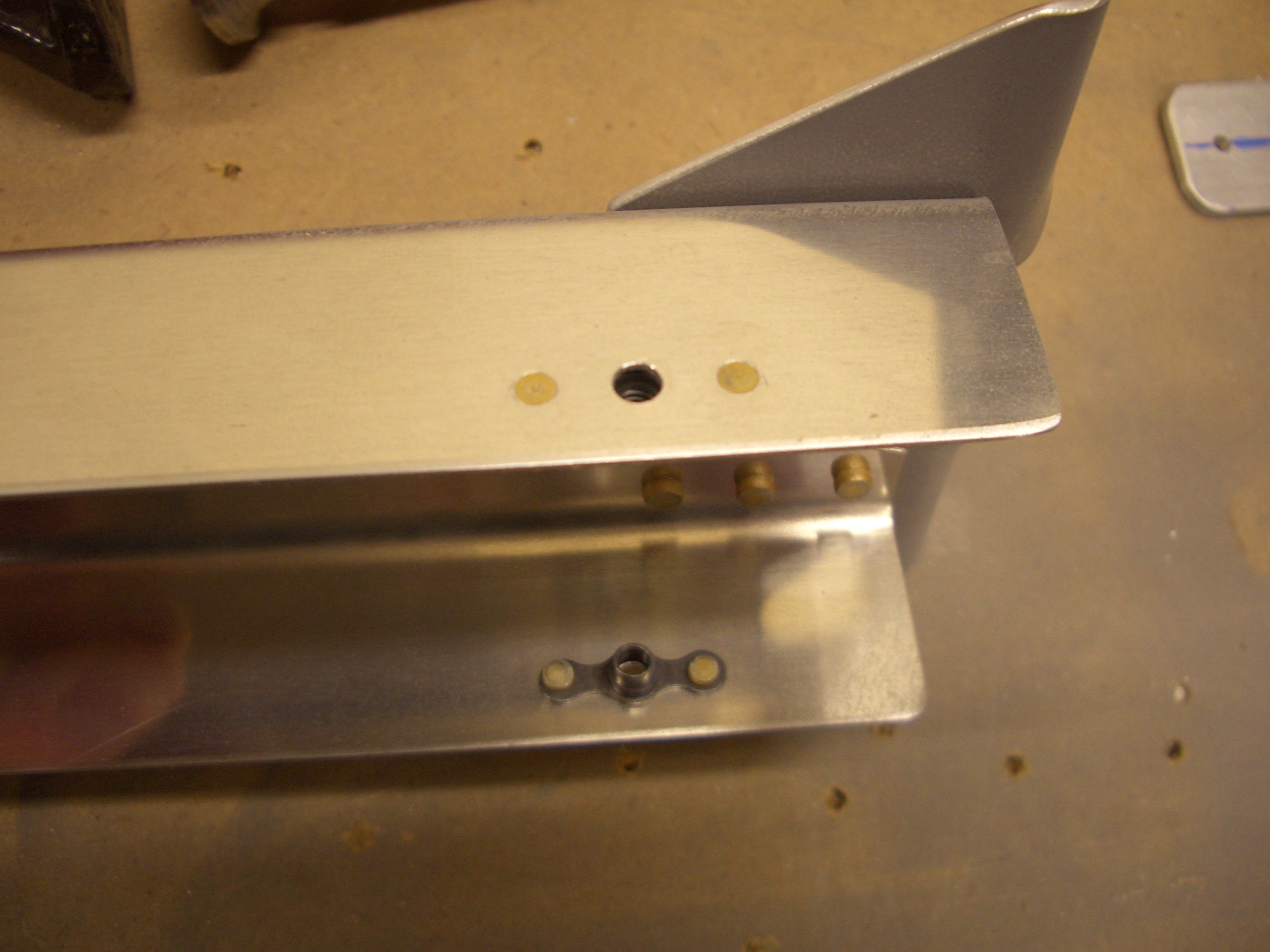
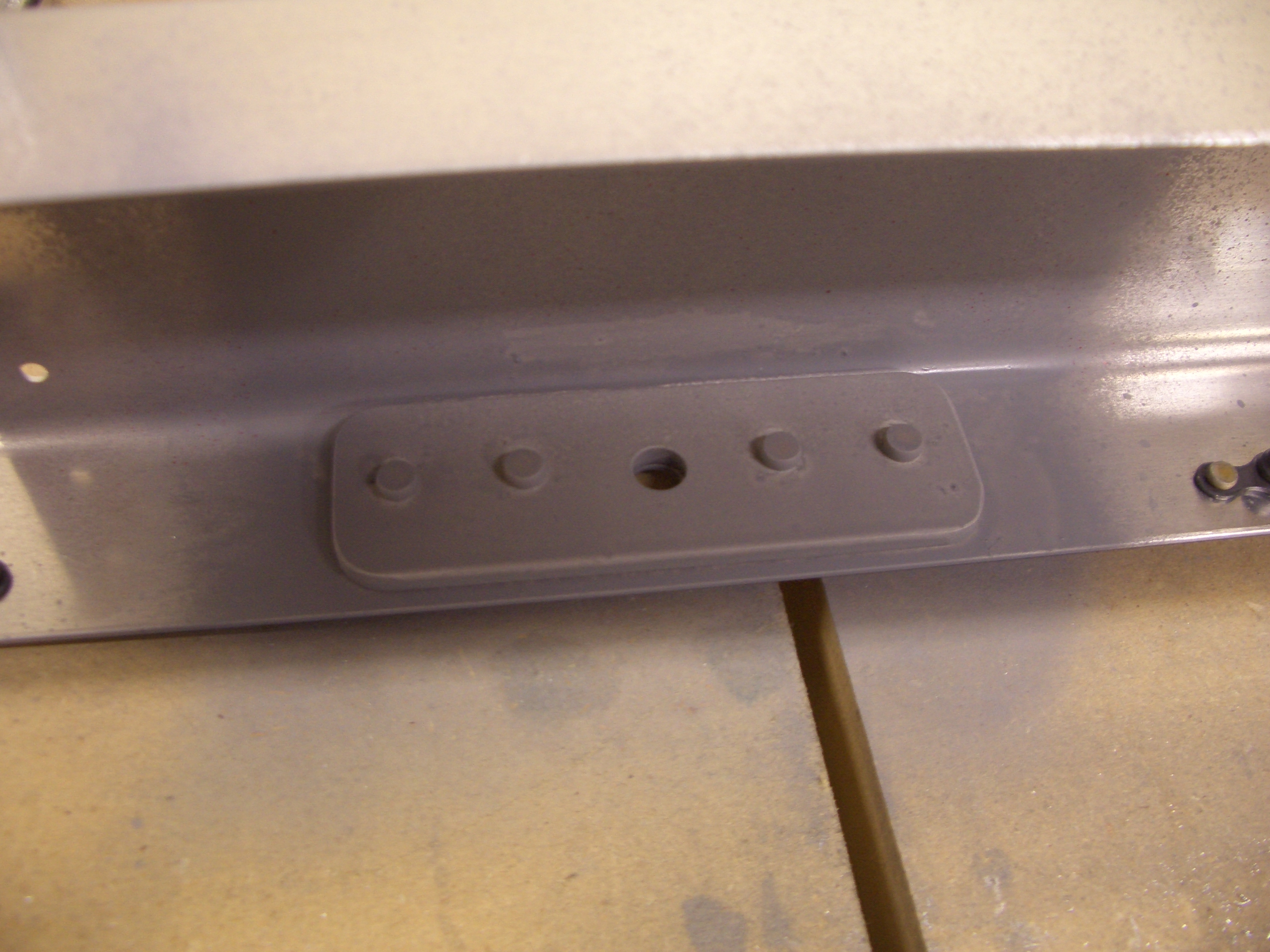
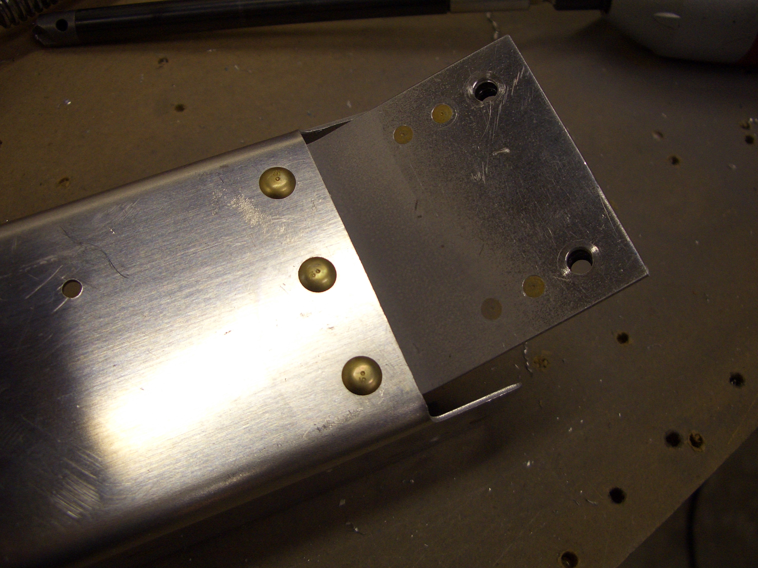
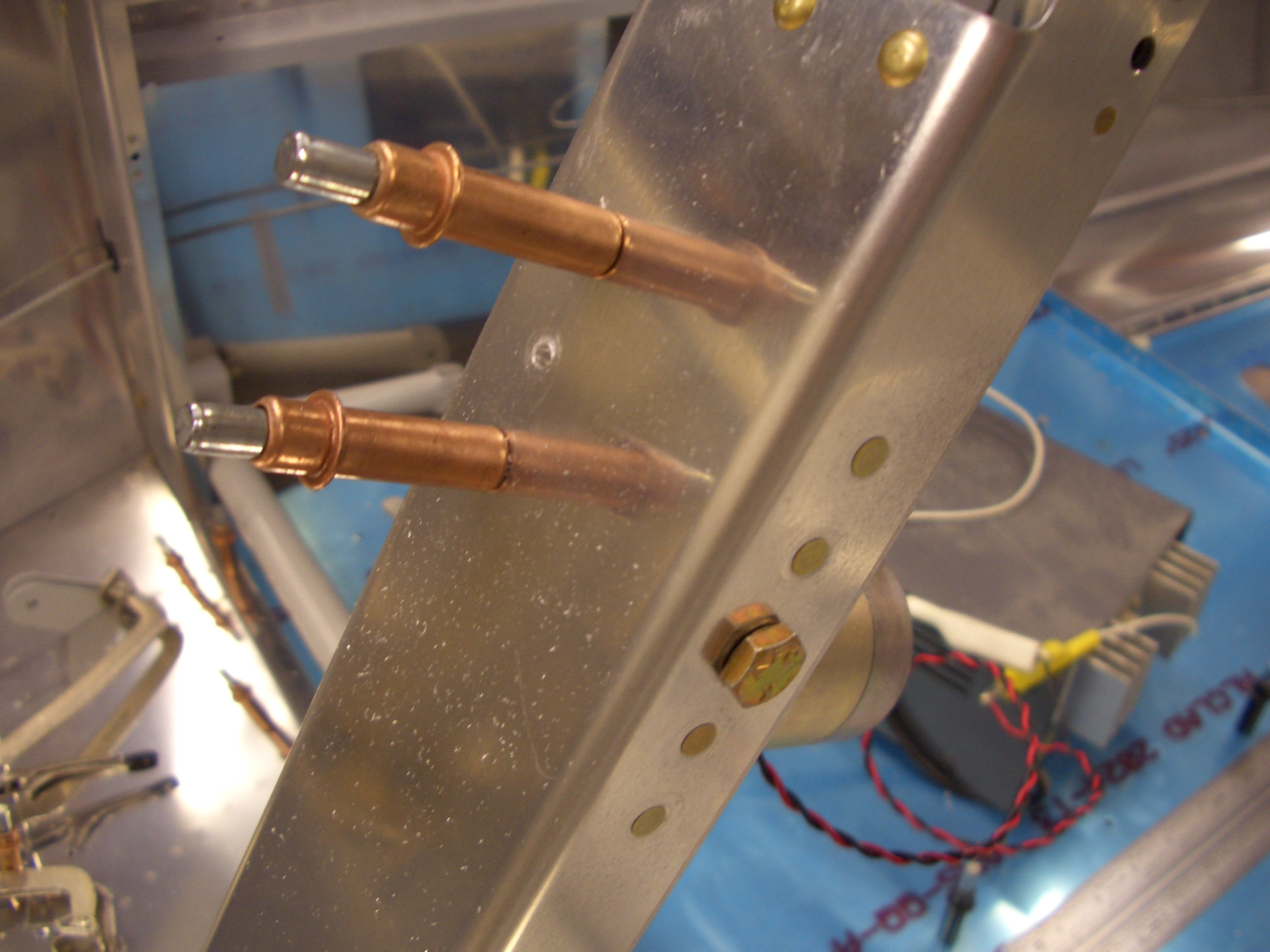
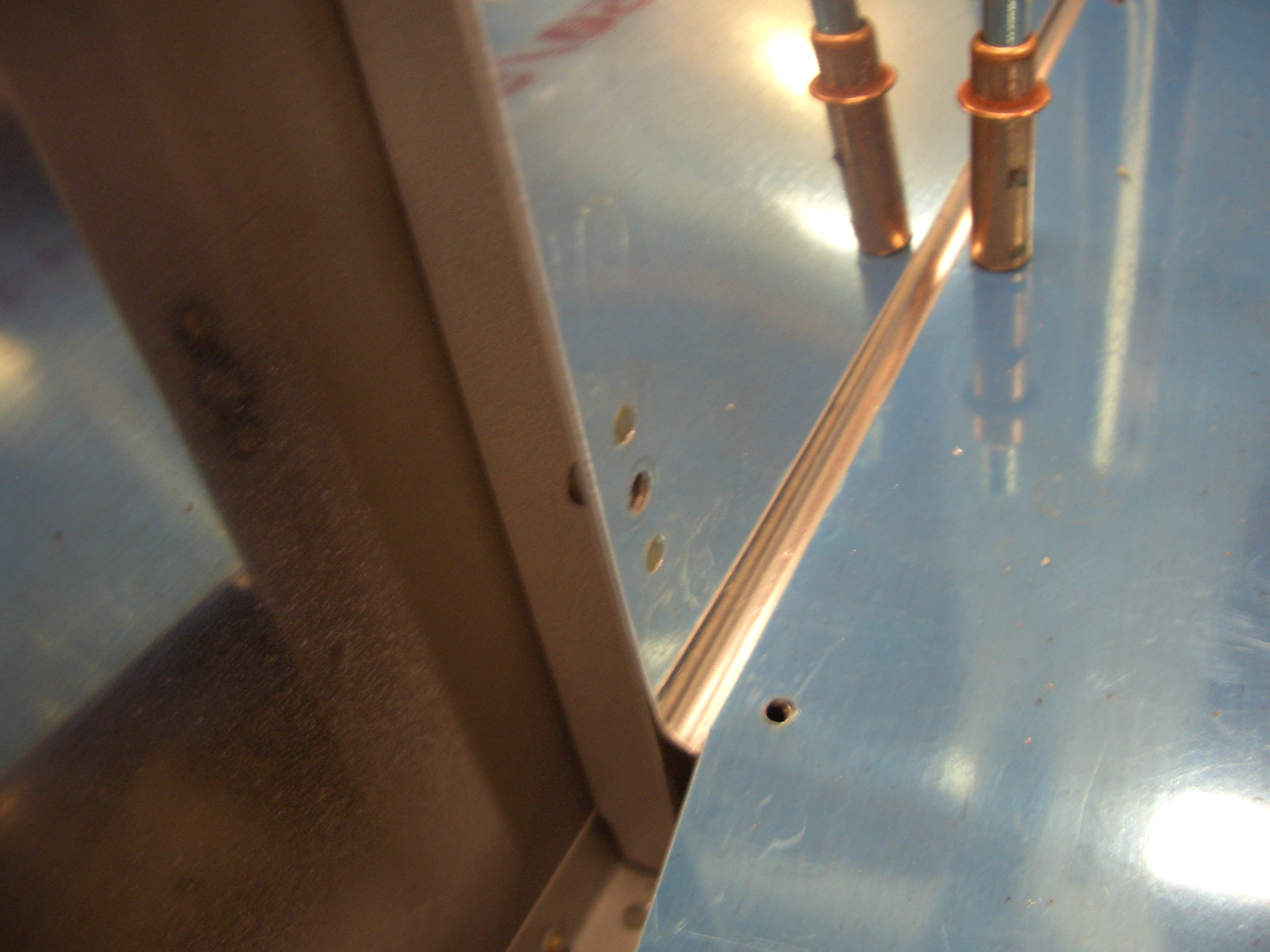
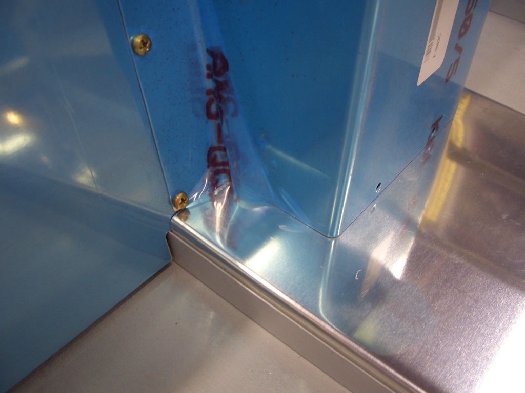
Since the lower portion of the vertical cover has the forward face removed for the fuel pump, I won’t use the lower two #19 holes to tie the two pieces together. This means I can move the lower cover back to eliminate the gap between the lower cover and the spar forward covers. I started trying to lay out the holes through the floor stiffeners that attach the lower cover, but the aft holes will also attach the fuel pump mounting bracket, so I want to make sure that it position first.
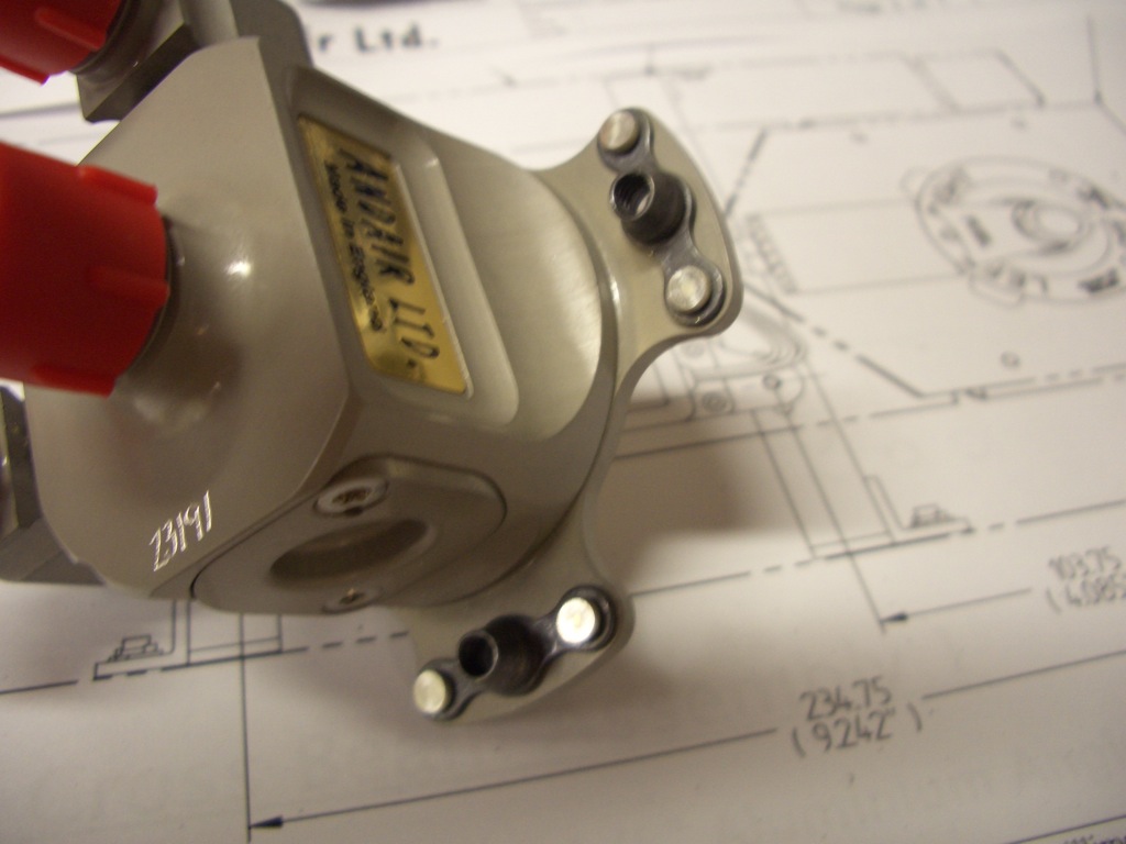
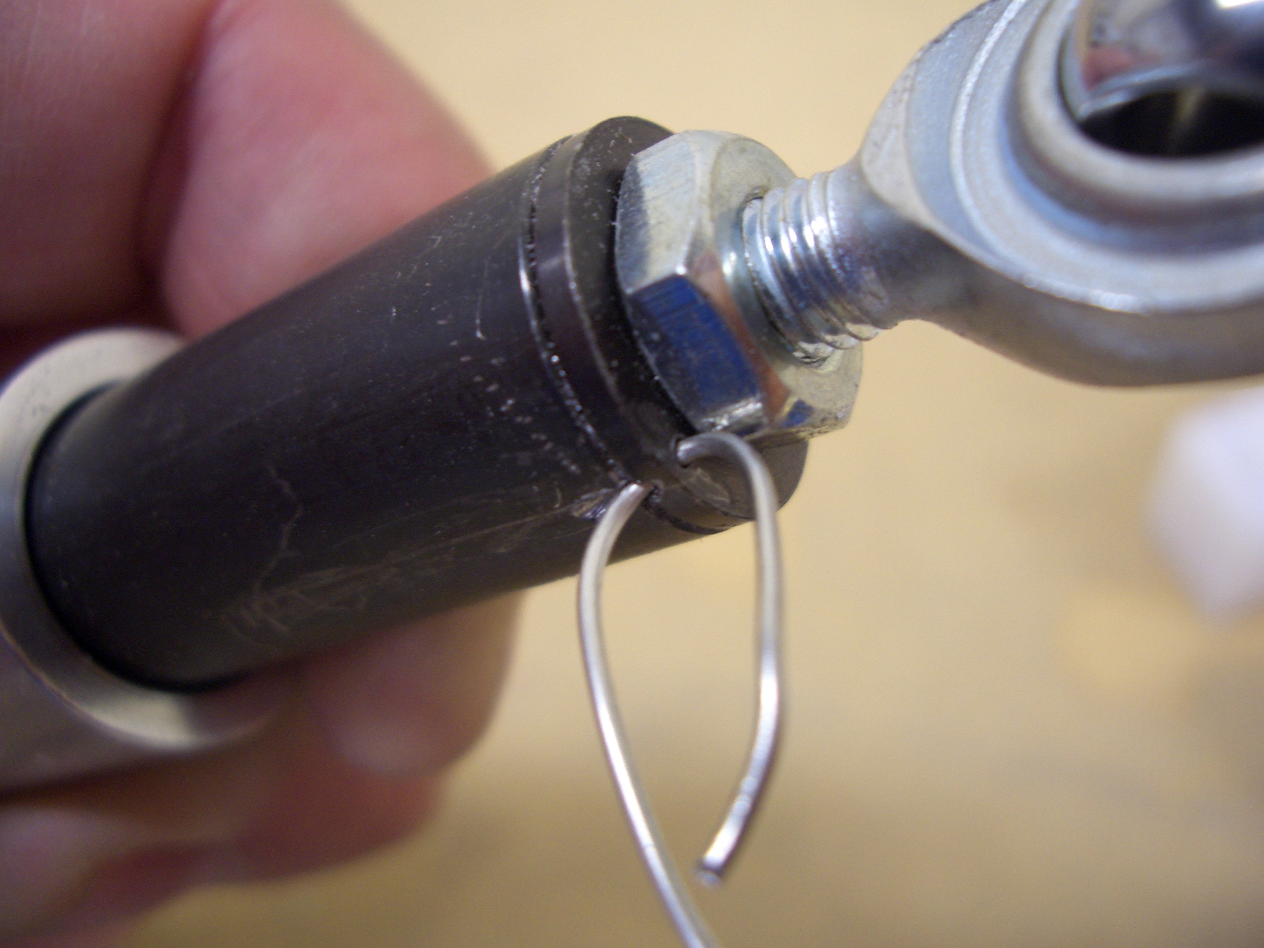
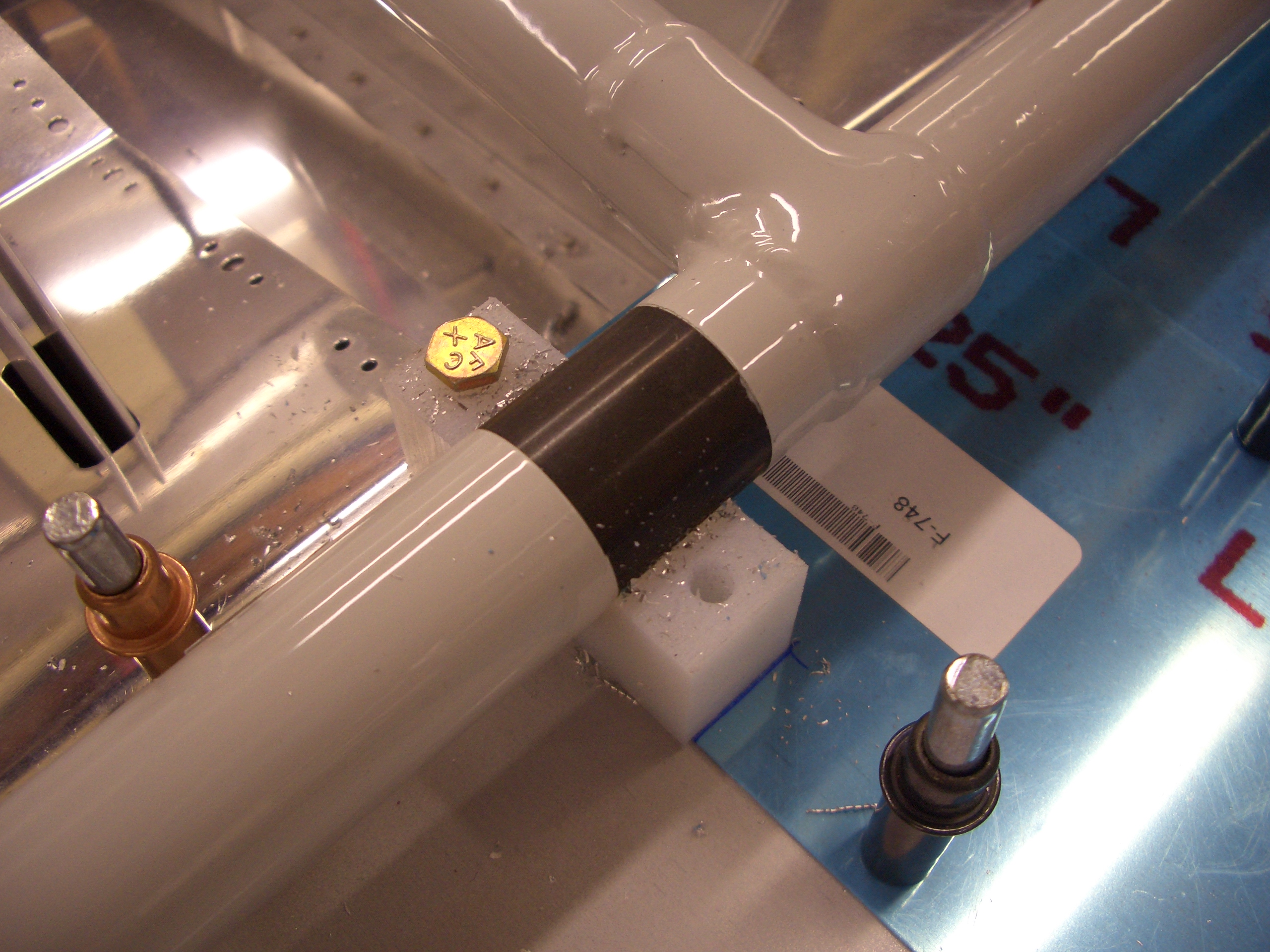
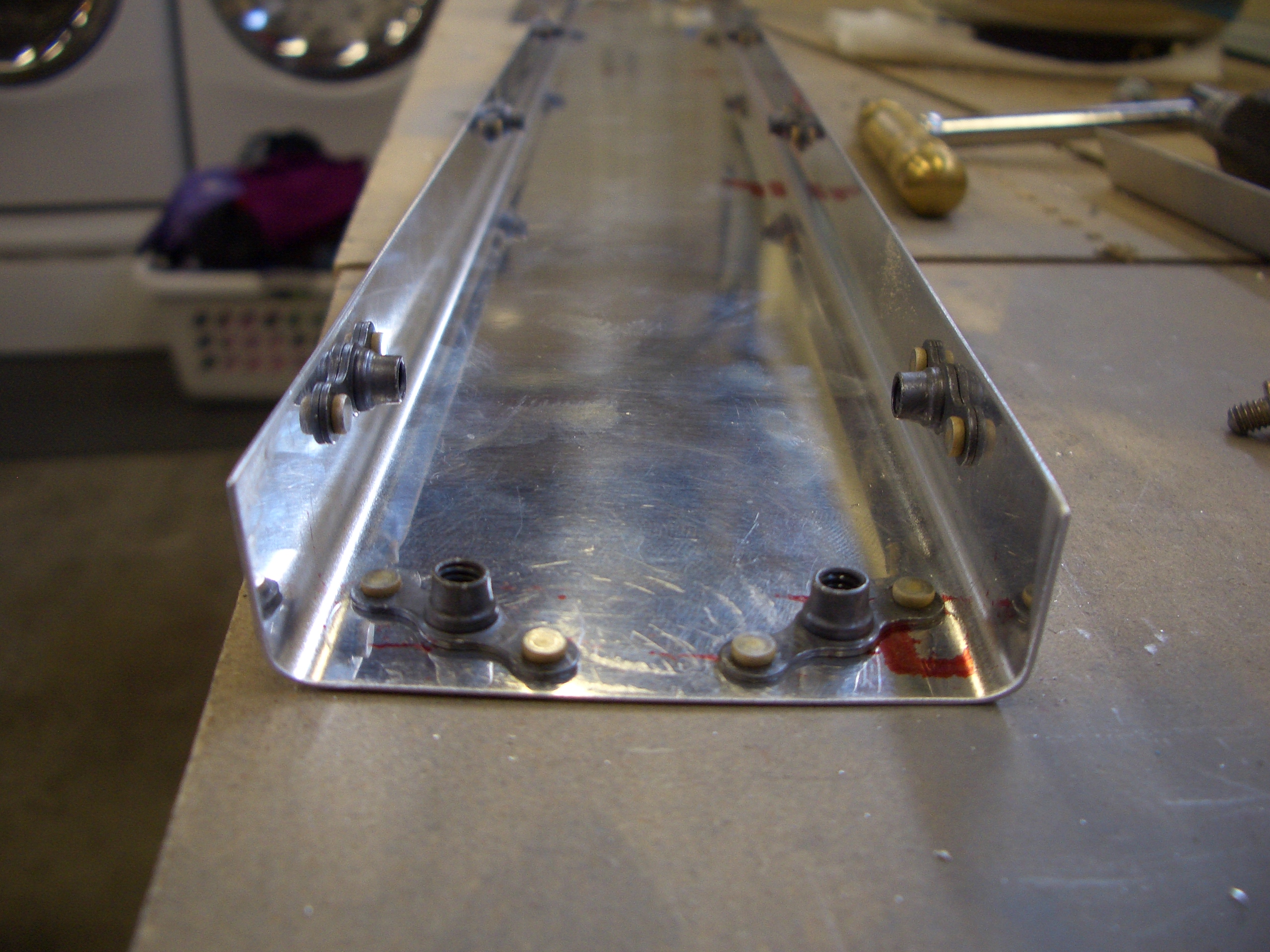
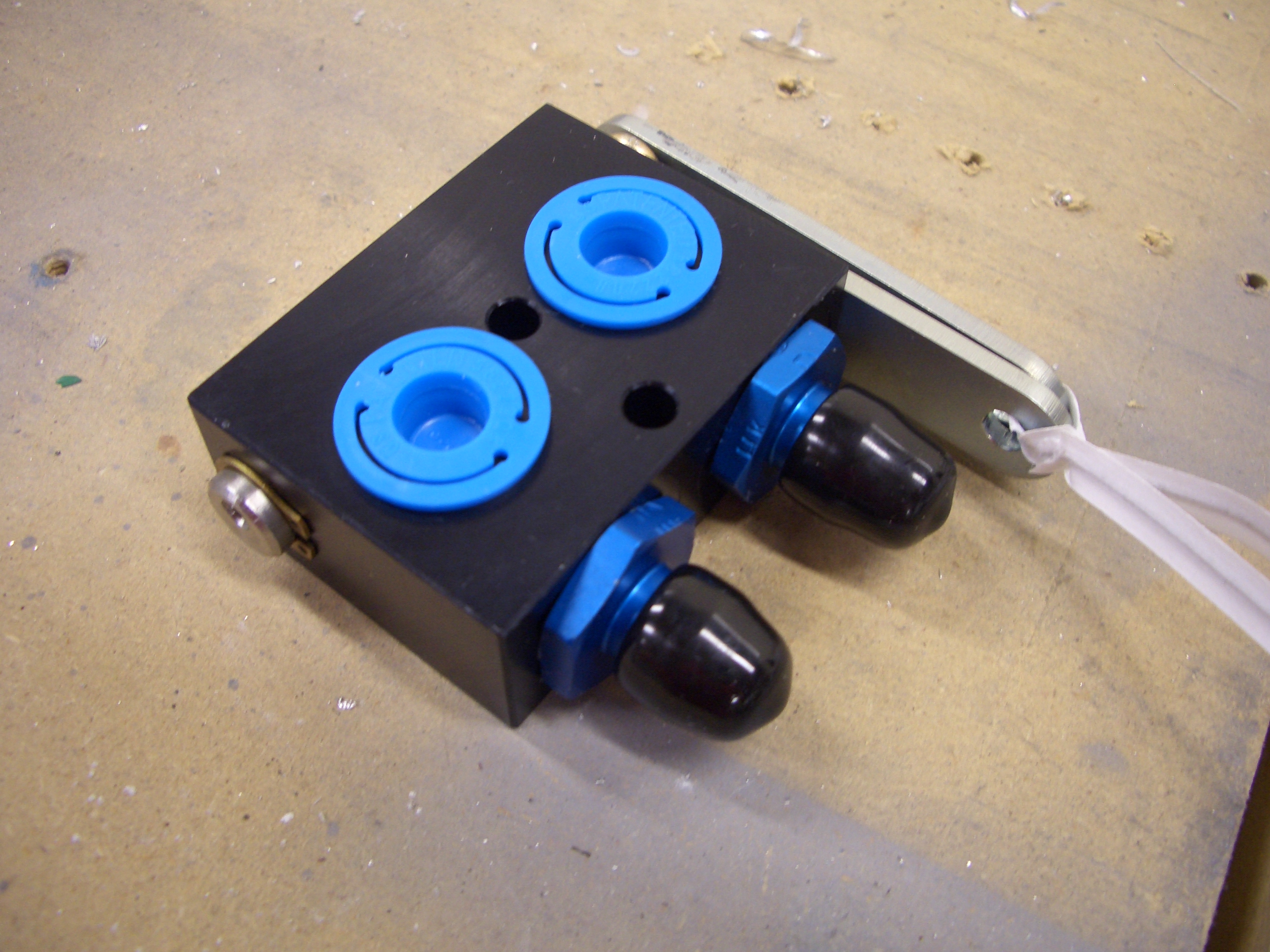
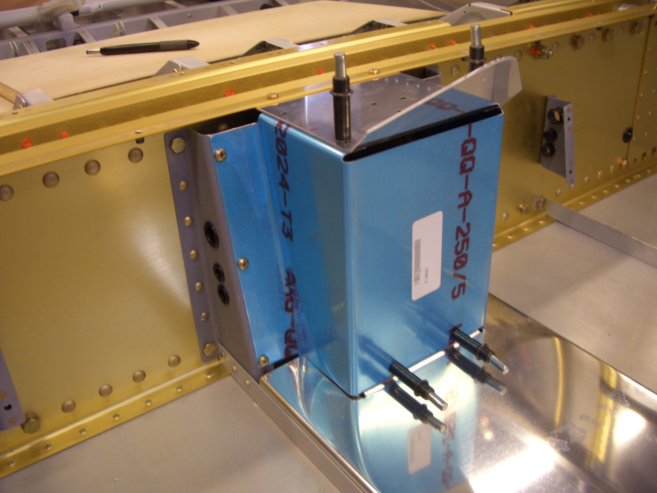
The Andair fuel selector valve intlets can be installed in any cardinal orientation and are held in place with four stainless steel screws. I used some fuel lube to lubricate the o-rings, and them installed the inlets facing down.
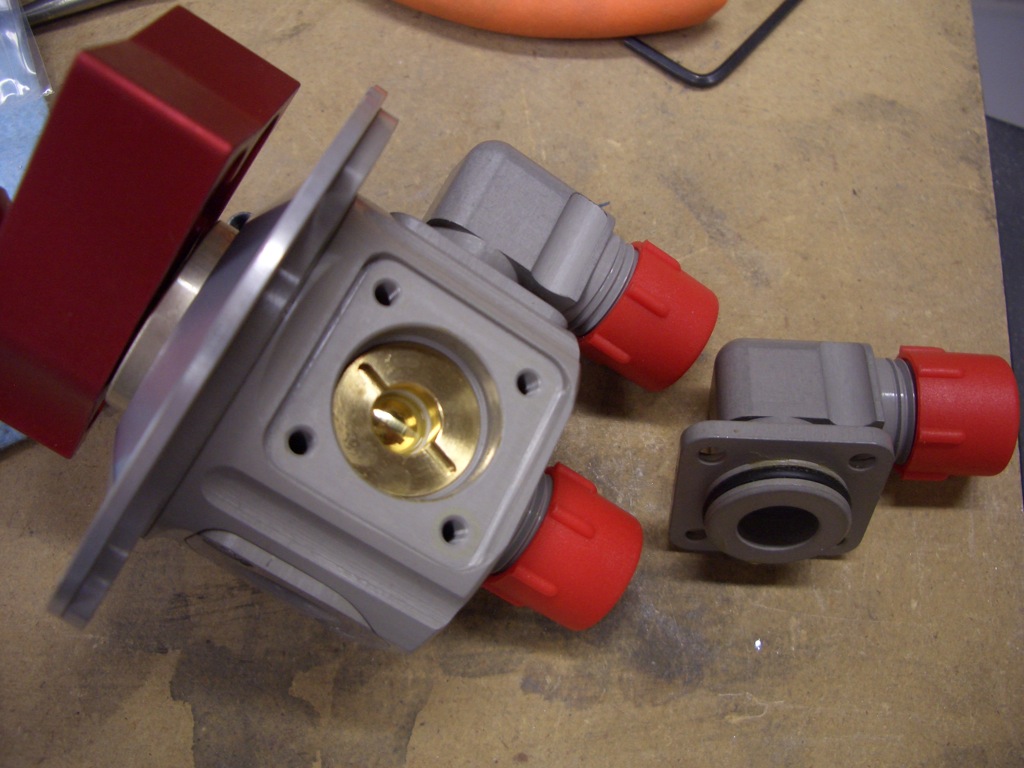
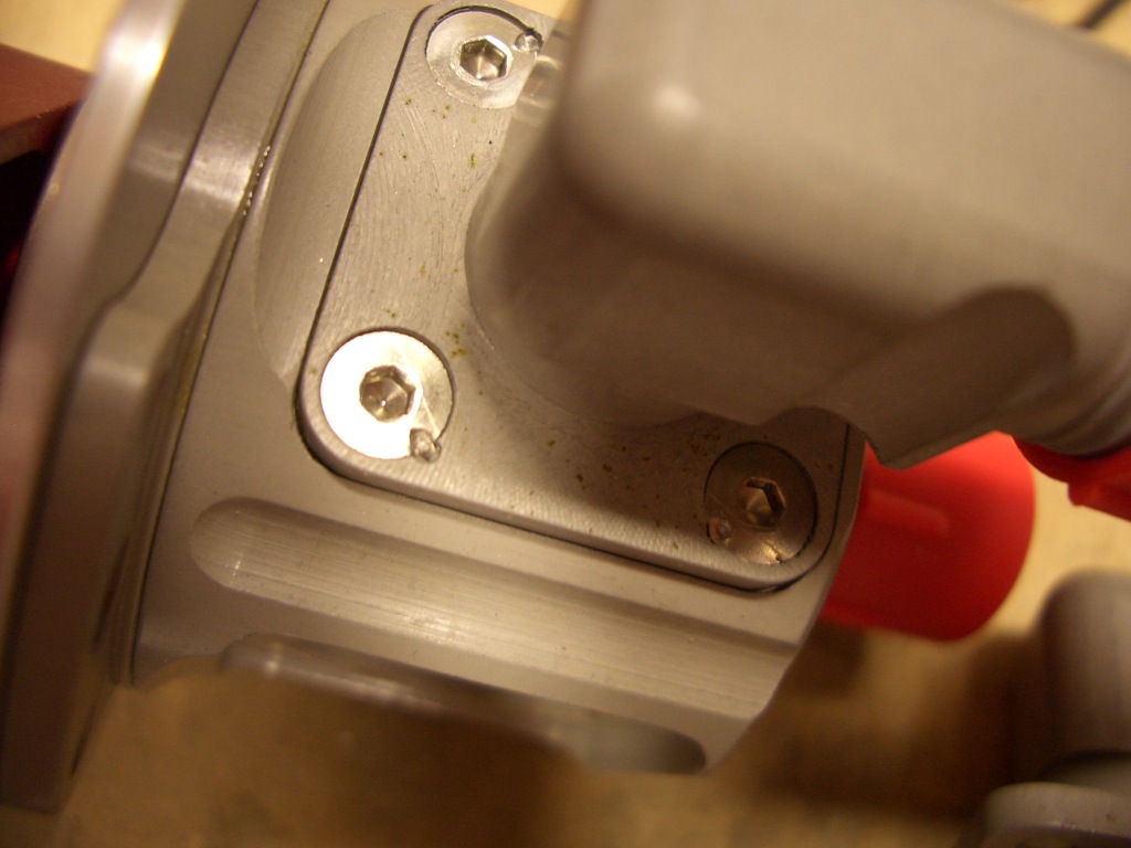
After installing the stainless steel screws, a punch is used to deform the screw into a recess to prevent it from backing out.
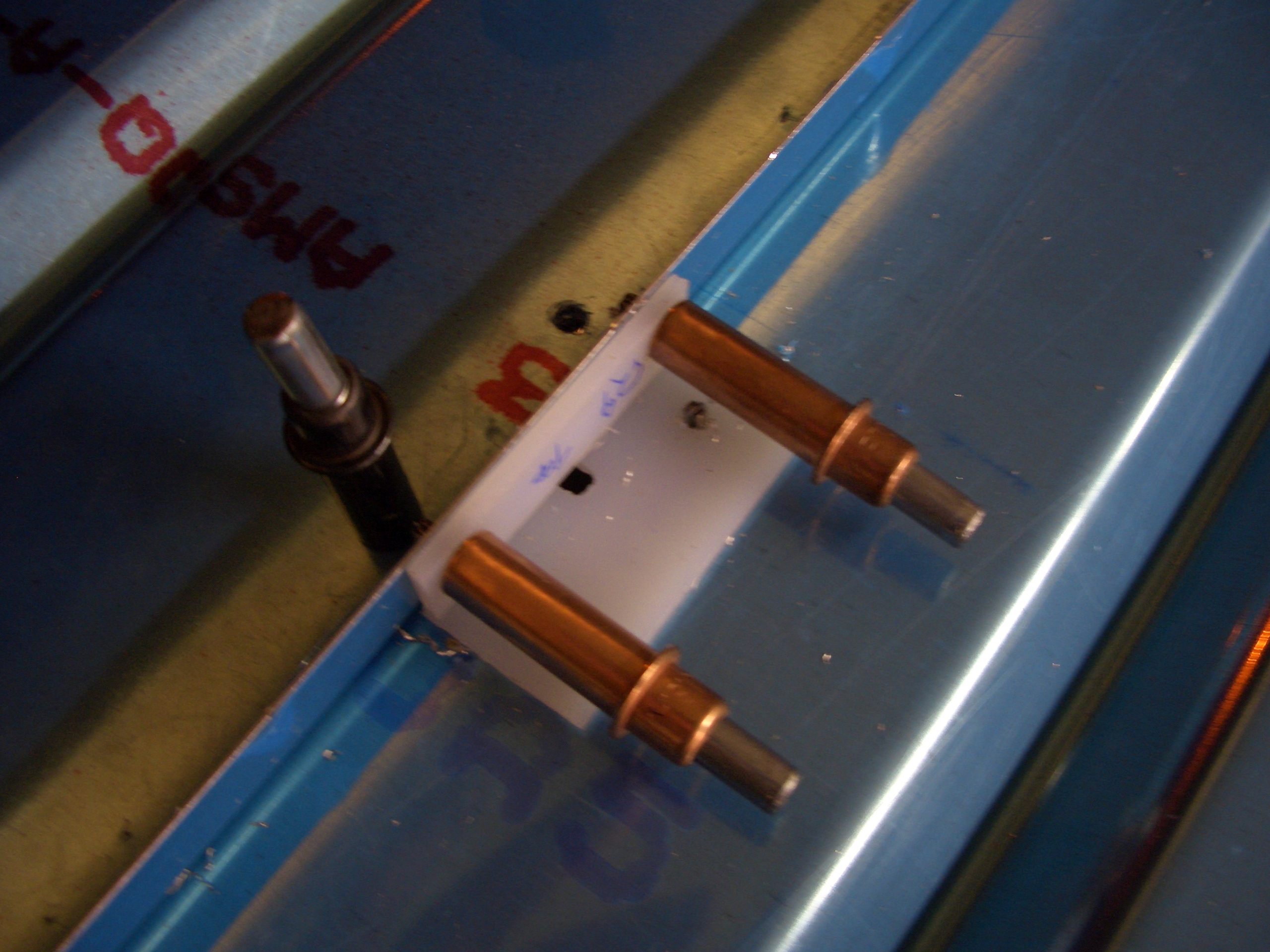
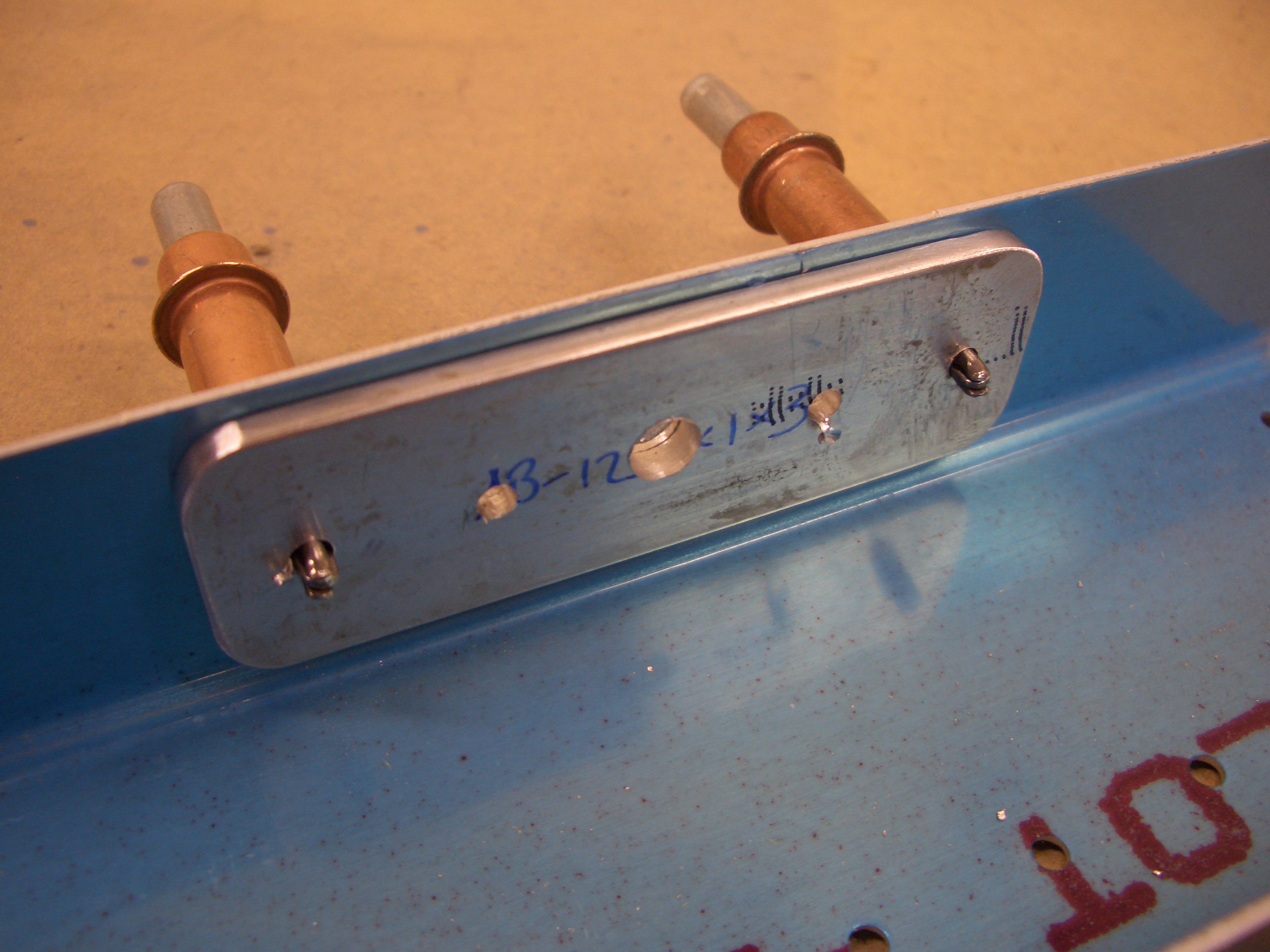
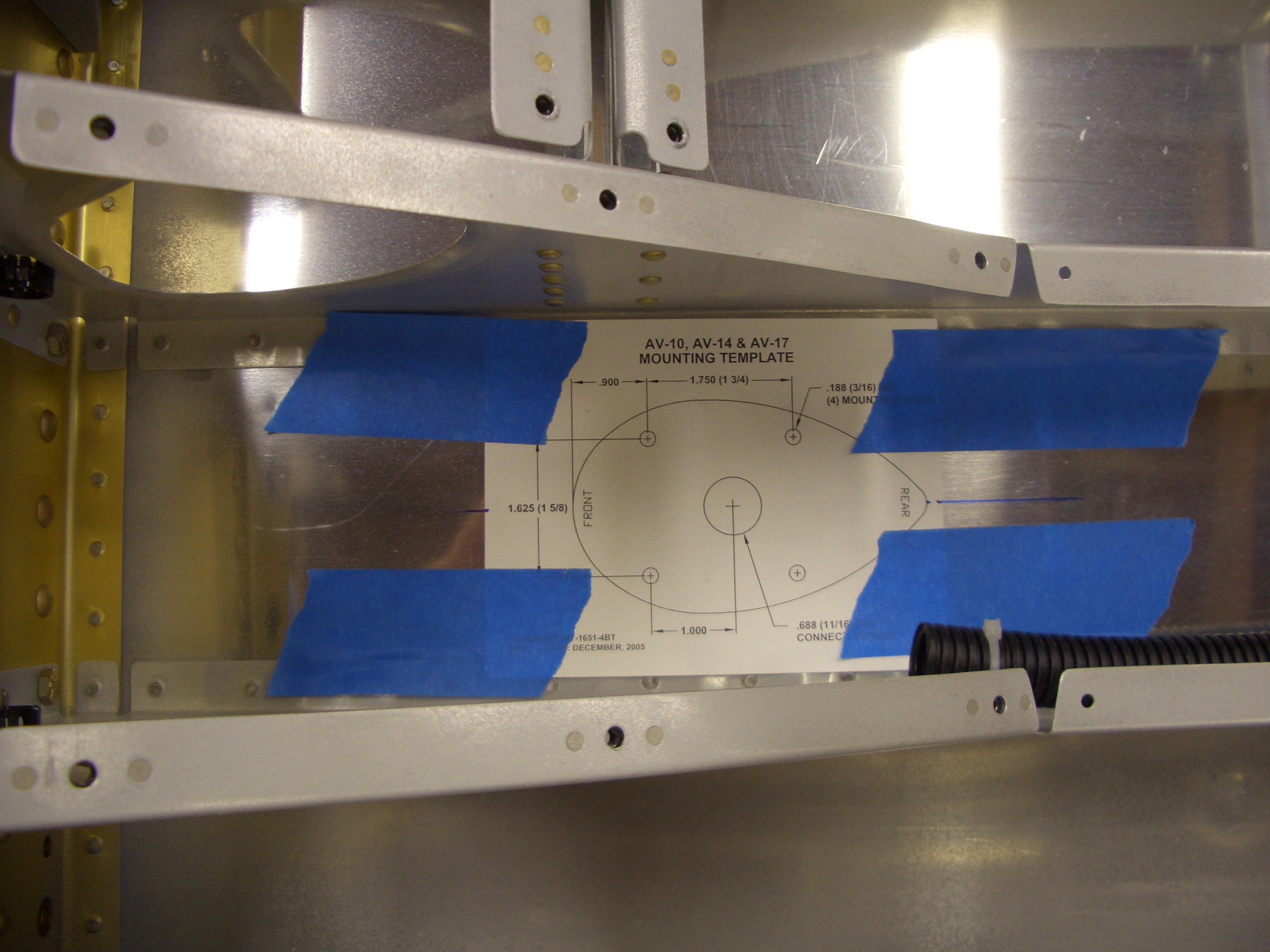
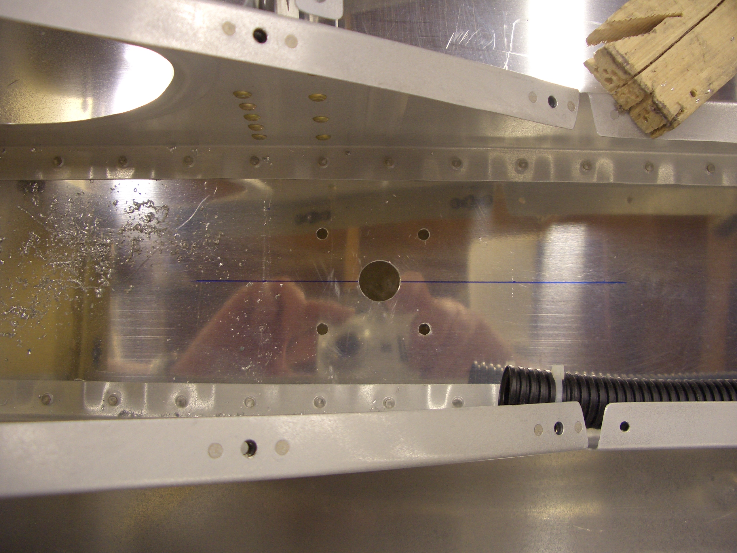
I drilled the fuel selector mounting bracket for the fuel selector by first drilling a 1″ hole inthe middle. I purchased a large unibit knockoff from Harbor Freight a few weeks ago to make larger holes like this. Unfortunately, it is a complete piece of shit and took several minutes to enlarge this hole from 7/8″ to 1″. After drilling the large hole, the valve was positioned and the three outer holes are drilled for the mounting screws.
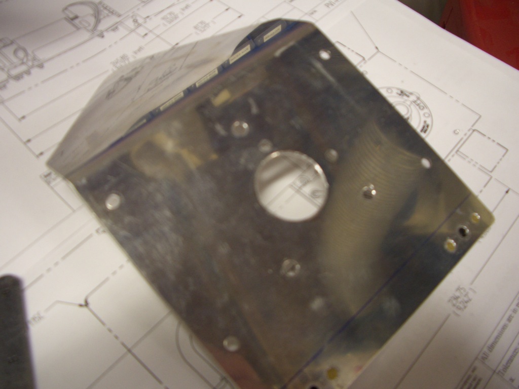
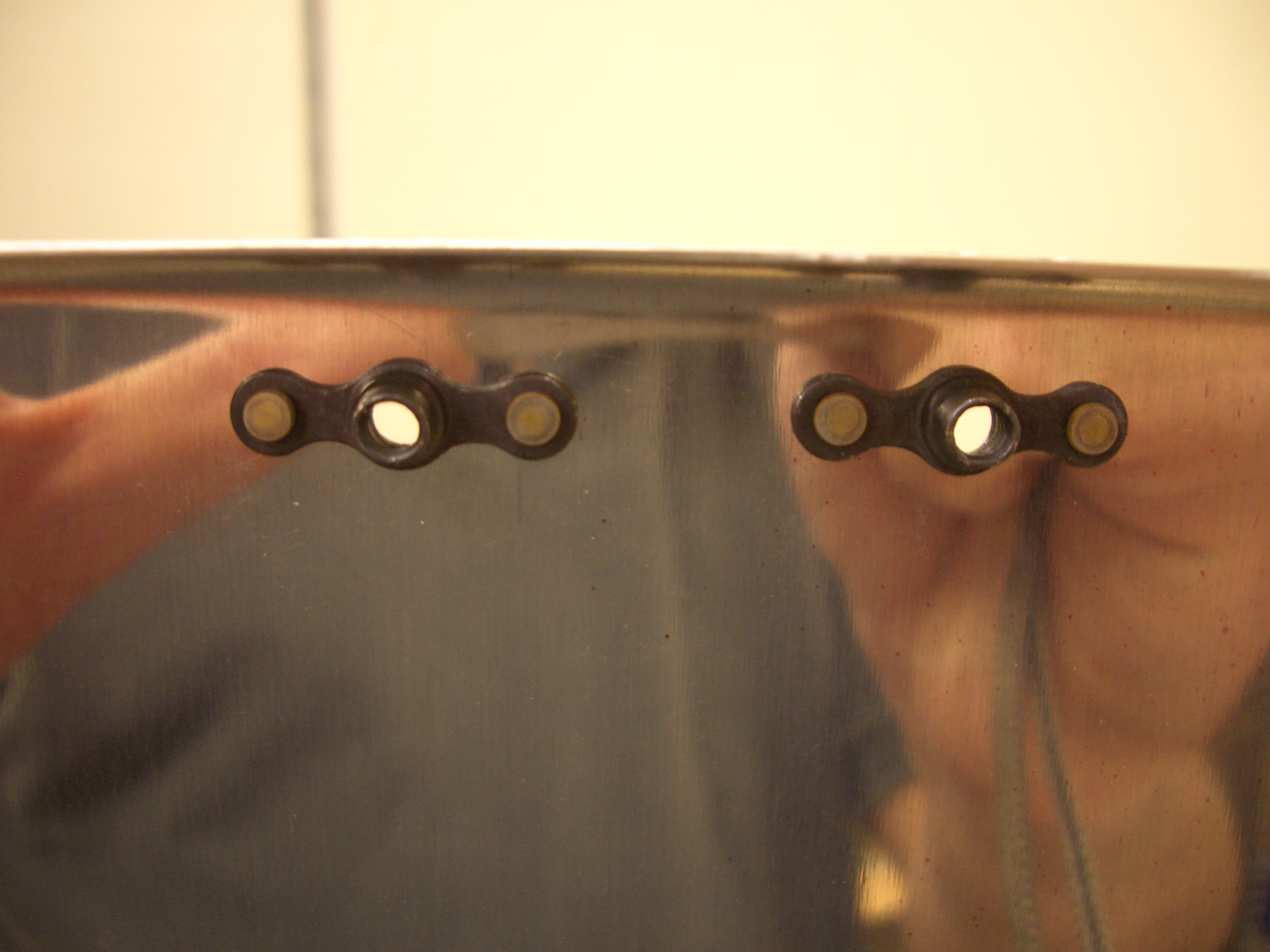
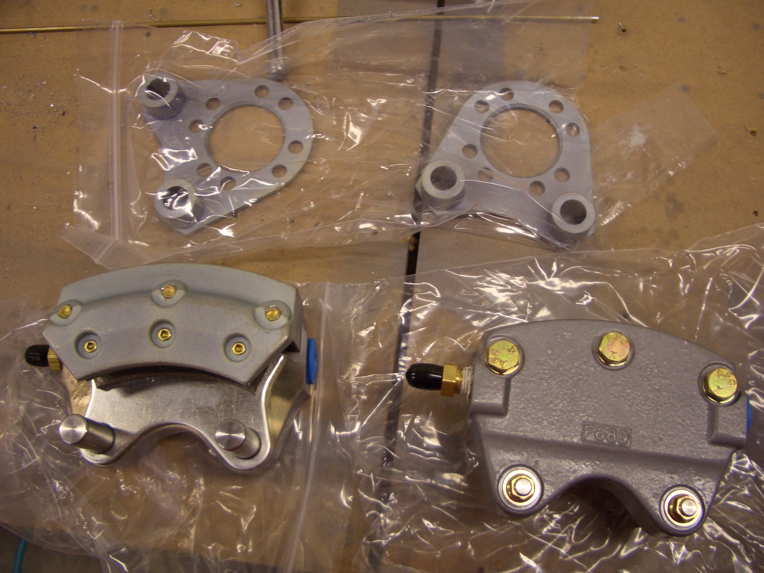
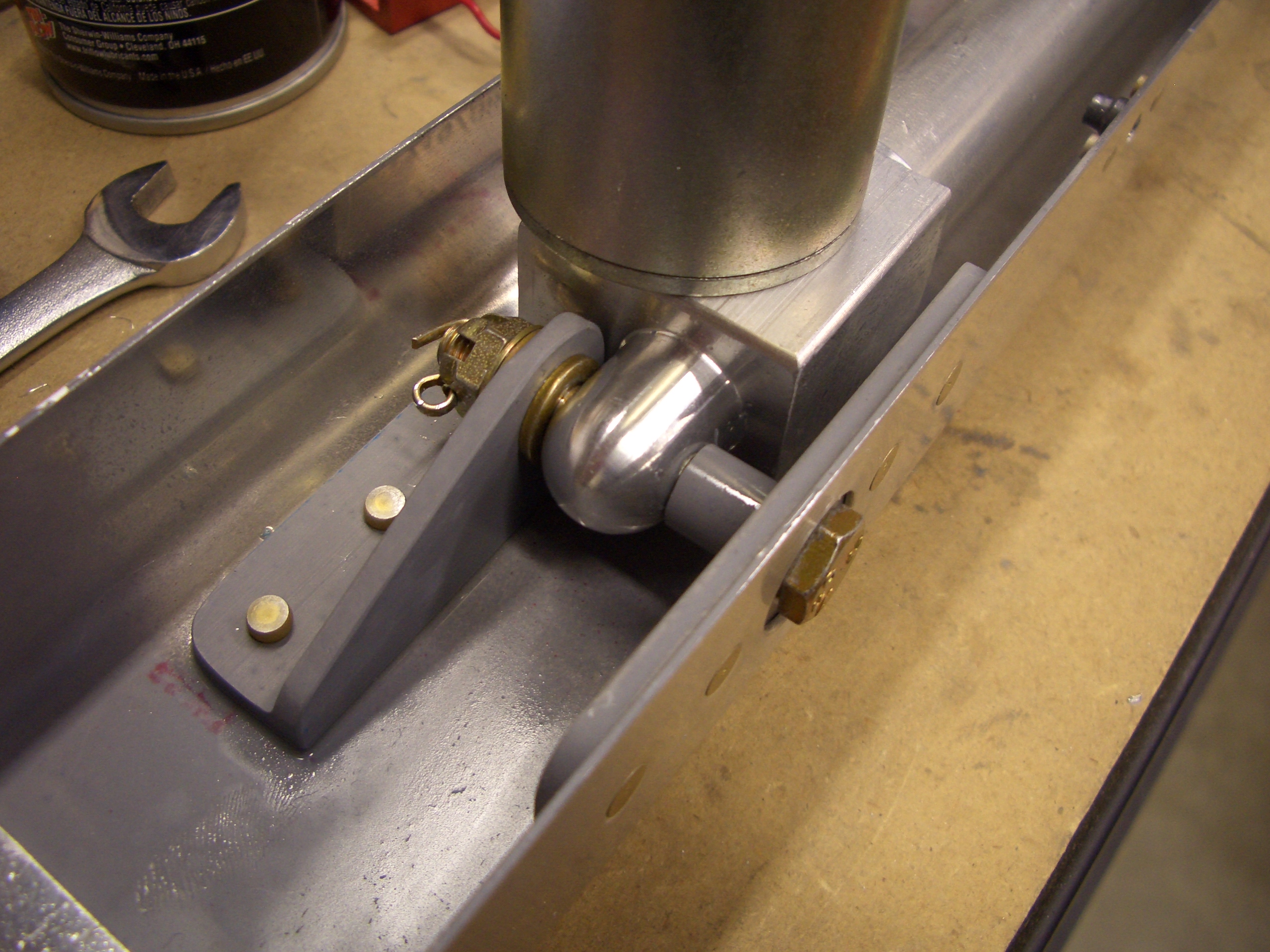
Finally, K1000-08 nutplates can be installed on the valve and the valve can be installed on the mounting bracket. I spent a little time trying to bend a 3/8″ fuel line to connect the fuel selector outlet to the fuel pump, but I don’t think I can bend the line according to the plans since the bend radius is tighter than my bender allows. This probably means that I’ll need to install the fuel pump slightly forward of the specified location.